CONTENTS
SAFETY CAUTION
..
...............
..............................................................................
3
1. SPECIFICATIONS
..................................................................................................
8
2.
FAN CHARACTERISTICS
...............................................................................
.
......
9
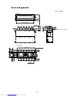
3. CONSTRUCTION VIEWS (EXTERNAL VIEWS)
................................................
.
...
1
0
4. WIRING DIAGRAMS ...............................................................................................
1
2
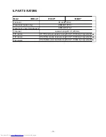
5. PARTS RATING .................................................................................................
.
.....
1
3
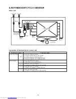
6. REFRIGERANT CYCLE DIAGRAM .....................................................................
.
..
1
4
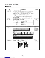
7. CONTROL OUTLINE .............................................................................................
.
.
15
8. APPLIED CONTROL AND FUNCTIONS
(INCLUDING CIRCUIT CONFIGURATION) .....................................................
.
..
.
..
.
.
2
1
8-1. Indoor control block diagram ...........................................................
...
.....................
.
........
2
1
8-1-1. In Case of Connection of Wired (Simple) Remote Control
.
....
............................
2
1
8-1-2. In Case of Connection of Wireless Remote Control
.
....
......................................
2
2
8-1-3. Connection of Both Wired (Simple) Remote Control and Wireless Remote
Control .
.....
................................................
........................................................
.......
2
3
8-2. Indoor
Circuit Design Board MCC-1643
....................................................
......
.............
....
2
4
8-2-1.
Optional connector specifications of indoor P.C. board
............
.....
....................
25
8-
3
. Test operation of indoor unit .............................................................................................
28
8-
4
. Method to set indoor unit function DN code ....................................................................
29
8-
5
. Applied control of indoor unit ...........................................................................................
32
9. TROUBLESHOOTING ......................................................................................
.
......
48
9-1. Overview ..............................................................................................................................
48
9-2. Troubleshooting method .................................................................................................
.
.
49
9-3. Troubleshooting based on information displayed on remote control ..
....
.....................
5
5
9-4. Check codes displayed on remote control and SMMS outdoor unit
(7-segment display on I/F board) and locations to be checked .........................
.
...........
59
9-5. Sensor characteristics .......................................................................................................
7
5
10.
R
EPLACEMENT OF SERVICE P.C. BOARD
.............
.............
............................
76
10-1.
Indoor
C
ircuit Design Board (MCC-1643)
........................................................................
76
11. DETACHMENTS .............................................................................................
..
....
8
2
12. EXPLODED VIEWS AND PARTS LIST .........................................................
..
....
9
2
10-
2
.
Fan IPDU P.C. Board (MCC-1610)
............................................................
...........
..............
8
1
8
-
2-2
.
Fan IPDU P.C. Board (MCC-1610)
.....................................................
........
..............
26
8
-
2-3
.
Noise filter (MCC-1551)
........................................
................
.............
........
..............
27
8-
6
. Appli
cation control
P.C.Board
(pre-in
s
talled)
....
.............................................................
46
- 2 -

