P.C. board
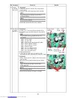
Screw A
⑤
Application
control
P.C. board
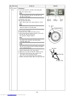
1.Detachment
1) Perform 1 of
①
to remove the electrical parts
box cover.
2) Take off the screws A and B then remove the
terminal block assembly.
3) Remove the CN1(RED) connector from the P.C. board.
NOTE
First unlock the housing and then remove the
connectors.
4) Unlock the locking card edge spacers (3 positions)
in the electrical parts box to remove the P.C. board.
2.Attachment
1) Mount the application control P.C. board in the
electrical parts box as before.
2) Be sure to wire in the electrical parts box as before.
NOTE 1
Check if there is no missing or contact failure
of the connectors.
NOTE 2
Be sure to wire as before.
3) Return terminal block assembly to the original
position without pinching wires.
Confirm to hook the claw of terminal block assembly
on the right side.
Then fix screw A and B.
4) Attach the electrical parts box cover as before.
CN1
Card edge spacer
(3 positions)
FAN control P.C. board
CN505(RED)
Control circuit board
Application control
P.C. board
Screw A
Terminal block assembly
Fixing claw for terminal block
CN1
Screw B
Cord clamp
- 85 -
No.
Part name
Procedure
Remarks


