– 35 –
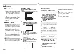
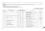
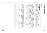
Confirmation of indoor unit setup
This check sheet is required for maintenance after installation. Be sure to fill this sheet and then pass this Installation Man
ual to the customers.
Indoor unit setup check sheet
Indoor unit
Indoor unit
Indoor unit
Indoor unit
Room name
Room name
Room name
Room name
Model
Model
Model
Model
Check indoor unit address. (For check method, refer to Service Manual of outdoor unit.)
*In case of a single system, it is unnecessary to enter the indoor address. (CODE NO.: Line [12], Indoor [13], Group [14], Cent
ral control [03])
Li
ne
Indoor
Group
Line
Indo
o
r
G
roup
Li
ne
Indoor
Group
Line
Indoor
G
roup
Central control address
Central control address
Central control address
Central control address
Vari
ous setup
Various
s
e
tup
V
ari
ous setup
V
a
riou
s
setup
Have you changed high ceiling setup? If not, fill check mark [×] in [NO CHANGE], and fill check mark [×] in [ITEM] if changed,
respectively.
(For check method, refer to Applicable controls in this manual.) * In case of replacement of jumper blocks on indoor microcompu
ter P.C. board, setup is
automatically changed.
External static pressure
(CODE NO. [5d])
NO CHAN
G
E
STAND
A
RD
[0
000]
HIGH STATIC 1
[0
001]
HIGH STATIC 2
[0
003]
HIGH STATIC 3
[0
004]
HIGH STATIC 4
[0
006]
HIGH STATIC 3
[0
0
04]
HIGH STATIC 4
[0
0
06]
HIGH STATIC 3
[0
004]
HIGH STATIC 4
[0
006]
HIGH STATIC 3
[0
004]
HIGH STATIC 4
[0
006]
External static pressure
(CODE NO. [5d])
NO CHANGE
STANDARD
[0000]
HIGH STATIC 1
[0001]
HIGH STATIC 2
[0003]
External static pressure
(CODE NO. [5d])
NO
CH
ANGE
STAN
DARD
[0
0
0
0]
HI
GH STATIC
1
[0001]
HI
GH STATIC
2
[0003]
External static pressure
(CODE NO. [5d])
NO CHANG
E
STANDAR
D
[0000]
HIGH STA
TIC
1
[0001]
HIGH STA
TIC
2
[0003]
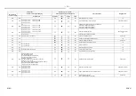
Have you changed lighting time of filter sign? If not, fill check mark [×] in [NO CHANGE], and fill check mark [×] in [ITEM] if
changed, respectively.
(For check method, refer to APPLICABLE CONTROLS in this manual.)
Filter sign lighting time
(CODE NO. [01])
NO CHAN
G
E
NONE
[0
000]
150 H
[0
001]
2500
H
[0
002]
5000
H
[0
003]
1000
0
H
[0
004]
Filter sign lighting time
(CODE NO. [01])
NO CHANGE
NONE
[0000]
1
5
0 H
[0001]
2
500 H
[0002]
5
000 H
[0003]
1
0000 H
[0004]
Filter sign lighting time
(CODE NO. [01])
NO
CH
ANGE
NO
NE
[0
0
0
0]
150 H
[00
01]
2500 H
[00
02]
5000 H
[00
03]
10000 H
[00
04]
Filter sign lighting time
(CODE NO. [01])
NO CHANG
E
NON
E
[0000]
150
H
[0001]
250
0 H
[0002]
500
0 H
[0003]
100
00 H
[0004]
Have you changed lighting time of filter sign? If not, fill check mark [×] in [NO CHANGE], and fill check mark [×] in [ITEM] if
changed, respectively.
(For check method, refer to Applicable controls in this manual.)
Detected temp. shift value setup
(CODE NO. [06])
NO CHAN
G
E
NO SHIFT
[0
000]
+1 °C
[0
001]
+2 °C
[0
002]
+3 °C
[0
003]
+4 °C
[0
004]
+5 °C
[0
005]
+6 °C
[0
006]
Detected temp. shift value setup
(CODE NO. [06])
NO CHANGE
NO SHIFT
[0000]
+
1
°C
[0001]
+
2
°C
[0002]
+
3
°C
[0003]
+
4
°C
[0004]
+
5
°C
[0005]
+
6
°C
[0006]
Detected temp. shift value setup
(CODE NO. [06])
NO
CH
ANGE
NO SHIFT
[00
00]
+1 °C
[00
01]
+2 °C
[00
02]
+3 °C
[00
03]
+4 °C
[00
04]
+5 °C
[00
05]
+6 °C
[00
06]
Detected temp. shift value setup
(CODE NO. [06])
NO CHANG
E
NO SHIFT
[0000]
+1 °C
[0001]
+2 °C
[0002]
+3 °C
[0003]
+4 °C
[0004]
+5 °C
[0005]
+6 °C
[0006]
Remote controller sensor
(CODE NO. [32])
NO CHAN
G
E
NOT IN
USE
[0
0
00]
IN
USE
[0
0
01]
Remote controller sensor
(CODE NO. [32])
NO CHANGE
NOT IN USE
[0000]
IN USE
[0001]
Remote controller sensor
(CODE NO. [32])
NO
CH
ANGE
N
O
T
IN
U
S
E
[0
0
0
0
]
IN USE
[00
01]
Remote controller sensor
(CODE NO. [32])
NO CHANG
E
NOT IN USE
[0000]
IN USE
[0001]
Incorporation of parts sold
separately
Incorporation of parts
sold separately
Incorporation of parts sold
separately
Incorporation of parts sold
separately
Ot
her
s (
)
Ot
her
s (
)
Other
s (
)
Other
s (
)
Ot
hers (
)
Ot
hers (
)
O
th
e
rs (
)
O
th
e
rs (
)
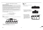
Prior to delivery to the customer, check the address and setup of the indoor unit, which has been installed in this time and fi
ll the
check sheet (Table below). Data of four units can be entered in this check sheet. Copy this sheet according to the No. of the i
ndoor
units. If the installed system is a group control system, use this sheet by entering each line system into each installation ma
nual
attached to the other indoor units.
■
REQUIREMENT
69-EN
70-EN


