– 26 –
7. APPLIED CONTROL AND FUNCTIONS
(INCLUDING CIRCUIT CONFIGURATION)
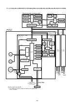
7-1. Indoor controller block diagram
7-1-1. In Case of Connection of Wired (Simple) Remote Controller
M
a
x.
8
u
nit
s
a
re connect
ab
le.
*1 The
s
ched
u
le timer c
a
nnot
b
e connected to the
s
imple wired
remote controller.
A
B
L
N
Driver
Indoor control P.C.
b
o
a
rd
(MCC-164
3
)
DC20V
DC12V
DC5V
DC
2
8
0V
O
u
t
s
ide o
u
tp
u
t
MCU
U1 U2
U1 U2
Power
su
pply
1Ø220-240V, 50Hz
1Ø220V, 60Hz
Indoor/O
u
tdoor
comm
u
nic
a
tion
Indoor unit
#1 (He
a
der)
PMV
Lo
u
ver
motor
Indoor
f
a
n motor
CPU
DC5V
DC5V
*1
CN2
CN1
Wired(Simple) header remote controller
(Up to 2 units)
Schedule timer
F
u
nction
s
et
u
p
LCD
driver
CPU
Power
circ
u
it
EEPROM
TA
s
en
s
or
TC1
s
en
s
or
TC2
s
en
s
or
TCJ
s
en
s
or
HA
O
u
tdoor
u
nit
F
a
n motor
control cic
u
it
S
t
a
rt/Al
a
rm
BU
S
comm
u
nic
a
tion
circ
u
it
Power
circ
u
it
Power
circ
u
it
Remote controller
comm
u
nic
a
tion circ
u
it
Remote controller
comm
u
nic
a
tion circ
u
it
Di
s
pl
a
y
LCD
Di
s
pl
a
y LCD
Di
s
pl
a
y LED
EEPROM
S
econd
a
ry
ba
ttery
F
u
nction
s
et
u
p
Key
s
witch
Key
s
witch
Sa
me
as
left
Sa
me
as
left
#2
A
B
A
B
L
U1 U2
U1 U2
N
Power
su
pply
Power
su
pply
O
u
tdoor
u
nit
O
u
tdoor
u
nit
(Follower)
#
3
(Follower)
L N

