background image

Installation Manual

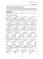
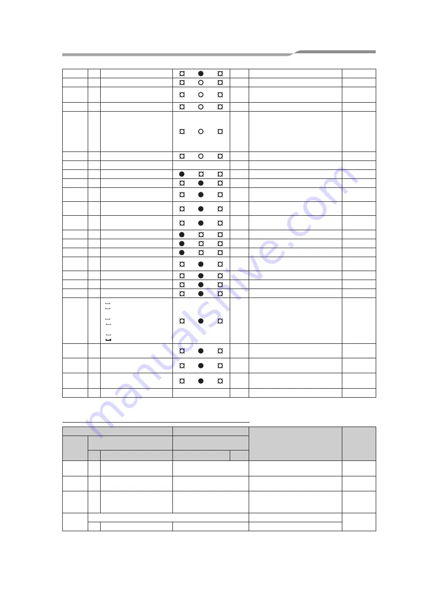
Error detected by TCC-LINK central control device

TCC-LINK: TOSHIBA Carrier Communication Link.

L09

SIM

Indoor capacity unset

Indoor

L10

L10

SIM

Outdoor capacity unset

I/F

L20

SIM

Duplicated central control addresses

AI-NET, 

Indoor

L28

L28

SIM

Over No. of connected outdoor units

I/F

L29

L29

01: IPDU1 error

02: IPDU2 error

03: IPDU3 error

04: Fan IPDU error

05: IPDU1 + Fan IPDU error

06: IPDU2 + Fan IPDU error

07: All IPDU error

SIM

No. of IPDU error

I/F

L30

L30 Detected indoor address

SIM

Indoor outside interlock

Indoor

L31

Extended I/C error

I/F

P01

ALT Indoor fan motor error

Indoor

P03

P03

ALT Discharge temp. TD1 error

I/F

P04

P04 01: Comp. 1 side

02: Comp. 2 side

ALT High-pressure SW system operation

IPDU

P05

P05 01: Phase-missing detection

02: Phase error

ALT Phase-missing detection /Phase error

I/F

P07

P07 01: Comp. 1 side

02: Comp. 2 side

ALT Heat sink overheat error

IPDU, I/F

P10

P10 Detected indoor address

ALT Indoor overflow error

Indoor

P12

ALT Indoor fan motor error

Indoor

P13

P13

ALT Outdoor liquid back detection error

I/F

P15

P15 01: TS condition

02: TD condition

ALT Gas leak detection

I/F

P17

P17

ALT Discharge temp. TD2 error

I/F

P19

P19 Detected outdoor unit number

ALT 4-way valve inverse error

I/F

P20

P20

ALT High-pressure protective operation

I/F

P22

P22

0

: IGBT short

1

: Fan motor position 

detective circuit error

3

: Fan motor trouble

C

: TH sensor temp. error 

(Heat sink overheat)

D

: TH sensor error

E

: Vdc output error

ALT Outdoor fan IPDU error

IPDU

P26

P26 01: Comp. 1 side

02: Comp. 2 side

ALT G-TR short protection error

IPDU

P29

P29 01: Comp. 1 side

02: Comp. 2 side

ALT

Comp position detective circuit system 
error

IPDU

P31

P31

ALT

Other indoor unit error 
(Group terminal unit error)

Indoor

By alarm device ALT

Error in indoor group

AI-NET

Check code

Wireless remote controller

Check code name

Judging 

device

Central 

control 

device 

indication

Outdoor 7-segment display

Sensor block display of 

receiving unit

Auxiliary code

OPERATION TIMER PRE.DEF. Flash

C05

Sending error in TCC-LINK central 
control device

TCC-LINK

C06

Receiving error in TCC-LINK central 
control device

TCC-LINK

C12

Batch alarm of general-purpose 
equipment control interface

General-

purpose 

equipment I/F

P30

Differs according to error contents of unit with occurrence of alarm Group control branching unit error

TCC-LINK

(L20 is displayed.)

Duplicated central control addresses

1111058602_EN.indd   35

11/24/16   11:41 AM

1111058602_EN.indd   36

11/24/16   11:41 AM

FILE NO. SVM-17045

- 102 -

Summary of Contents for MMK-AP0057HP-E

Page 1: ...R410A SERVICE MANUAL MULT TYPE High Wall Types MMK AP0057HP E TR MMK AP0077HP E TR MMK AP0097HP E TR MMK AP0127HP E TR June 2017 FILE NO SVM 17045 ...

Page 2: ...5 3 PARTS RATING 16 4 REFRIGERANTING CYCLE DIAGRAM 17 5 CONTROL OUTLINE 18 6 CONFIGURATION OF CONTROL CIRCUIT 24 7 APPLIED CONTROL 31 8 TROUBLESHOOTING 44 9 INSTALLATION MANUAL 68 10 HOW TO REPLACE MAIN PARTS 105 11 REPLACEMENT OF SERVICE INDOOR P C BOARD 112 12 EXPLODED VIEWS AND PARTS LIST 117 FILE NO SVM 17045 2 ...

Page 3: ...een trained and is thus thoroughly acquainted with the knowledge related to this work The qualified installer who is allowed to work at heights has been trained in matters relating to working at heights with the air conditioners made by Toshiba Carrier Corporation or alternatively he or she has been instructed in such matters by an individual or individuals who have been trained and is thus thorou...

Page 4: ...ectricians and from heat Insulating shoes Clothing to provide protection from electric shock Helmets for use in industry Shoes with additional protective toe cap Gloves to provide protection for electricians and from heat Indication DANGER WARNING CAUTION Explanation Indicates contents assumed that an imminent danger causing a death or serious injury of the repair engineers and the third parties w...

Page 5: ... unit Doing so may result in injury CAUTION BURST HAZARD Open the service valves before the operation otherwise there might be the burst CAUTION Do not climb onto the fan guard Doing so may result in injury Description WARNING ELECTRICAL SHOCK HAZARD Disconnect all remote electric power supplies before servicing WARNING Moving parts Do not operate unit with grille removed Stop the unit before the ...

Page 6: ...tion and contact a qualified service person Take steps to ensure that the power will not be turned on by marking out of service near the circuit breaker for instance until qualified service person arrives Continuing to use the air conditioner in the trouble status may cause mechanical problems to escalate or result in electric shocks or other failure When you access inside of the service panel to ...

Page 7: ...s with the ISO 14122 standard and follow the procedure in the ladder s instructions Also wear a helmet for use in industry as protective gear to undertake the work When working at heights put a sign in place so that no one will approach the work location before proceeding with the work Parts and other objects may fall from above possibly injuring a person below When executing address setting test ...

Page 8: ...s of refrigerant are mixed abnormal high pressure generates in the refrigerating cycle and an injury due to breakage may be caused When the air conditioner has been installed or relocated follow the instructions in the Installation Manual and purge the air completely so that no gases other than the refrigerant will be mixed in the refrigerating cycle Failure to purge the air completely may cause t...

Page 9: ...pened Running the compressor under condition that the valve closes causes an abnormal high pressure resulted in damage of the parts of the compressor and etc and moreover if there is leak of refrigerant at connecting section of pipes the air is sucked and causes further abnormal high pressure resulted in burst or injury Only a qualified installer 1 or qualified service person 1 is allowed to reloc...

Page 10: ...s to install the air conditioner Be sure to use the company specified products for the separately purchased parts Use of non specified products may result in fire electric shock water leakage or other failure Have the installation performed by a qualified installer Do not supply power from the power terminal block equipped on the outdoor unit to another outdoor unit Capacity overflow may occur on ...

Page 11: ...R MMK AP0077HP TR MMK AP0097HP TR MMK AP0127HP TR Super Modular Multi System Air Conditioner Super Heat Recovery Multi System Air Conditioner MiNi Super Modular Multi System Air Conditioner MiNi SMMS Complies with the provisions of the Machinery Directive Directive 2006 42 EC and the regulations transpos ing into national law NOTE This declaration becomes invalid if technical or operational modifi...

Page 12: ...ecause pipes are affected by impurities such as water oxide scales oil etc Use the clean pipes Be sure to brazing with flowing nitrogen gas Never use gas other than nitrogen gas 4 For the earth protection use a vacuum pump for air purge 5 R410A refrigerant is azeotropic mixture type refrigerant Therefore use liquid type to charge the refriger ant If using gas for charging composition of the refrig...

Page 13: ...um evacuating Refrigerant charge Refrigerant charge Gas leakage check Refrigerant charge R410A air conditioner installation Existence of Whether conven new equipment tional equipment for R410A can be used Yes Note 1 Yes Note 1 Yes No Yesa No Yes No Yes Yes Yes No Yes No Note 2 No Conventional air conditioner installation Whether new equipment can be used with conventional refrigerant Yes Note 1 No...

Page 14: ...t Panel Grille Inlet 798 114 340 97 24 Installation plate hanger 131 131 140 131 120 24 Installation plate hanger Drain hose 0 4m Installation plate hanger Connecting pipe 0 35m Flare 9 52mm Connecting pipe 0 40m Flare 6 35mm 510 40 298 94 94 135 170 170 135 40 144 144 170 170 192 192 Installation plate outline Center line Hanger Hanger Hanger Outline of indoor unit 65 65 19 17 5 58 Wireless remot...

Page 15: ... 2 1 BLU CN40 BLU BLU TC1 CN309 YEL 1 3 Power supply M 6 PMV U1 U2 OUTDOOR UNIT SUPPLY CIRCUIT POWER INFRARED RAYS RECEIVE AND INDICATION PARTS WP 033 GRN YEL COLOR IDENTIFICATION Indoor temp sensor TA TC1 TC2 TCJ TB01 TB02 Terminal Block FM F01 LM Fuse Fan Motor CN Symbol Connector Parts Name indicates the control P C board 1 Broken line indicate the wiring at site Long dashed short dashed line i...

Page 16: ... discharged according to cool heat mode 3 PARTS RATING 3 1 Parts Rating 3 2 Name of Each Part No 1 2 3 4 5 6 Parts Name Fan motor for indoor Louver motor Thermo Sensor TA sensor Heat exchanger sensor TC1 sensor Heat exchanger sensor TC2 sensor Heat exchanger sensor TCJ sensor Type ICF 340 30 6 24BYJ48A 080 418mm Ø4 600mm Ø6 800mm Ø6 500mm Specications Output Rated 30W DC340V 10kΩ at 25 C 10kΩ at 2...

Page 17: ...nnector CN82 6P Blue 1 Controls super heat in cooling operation 2 Controls under cool in heating operation 3 Recovers refrigerant oil in cooling operation 4 Recovers refrigerant oil in heating operation Connector CN104 2P White 1 Detects indoor suction temperature Connector CN100 3P Brown 1 Controls PMV super heat in cooling operation Connector CN101 2P Blue 1 Controls PMV under cool in heating op...

Page 18: ...e flashing change the mode on the wireless remote controller 1 Adjustment range Set temperature on remote controller C 2 From the item code 06 the setup temperature in heating operation can be corrected Setup at shipment 1 Based upon difference between Ta and Ts the operation frequency of the outdoor unit varies 1 By the command from the remote controller HIGH HH MED H or LOW L AUTO operation is e...

Page 19: ...of J zone operation of the the indoor fan in LOW L mode until it reaches the I I I I I zone It is reset when the following conditions are satisfied Reset conditions 1 TC1 12 C and TC2 12 C and TCJ 12 C 2 20 minutes passed after stop 2 In cooling operation the air conditioner operates as described below based upon temp detected by TC2 and TCJ sensors When M zone is detected for 45 minutes the force...

Page 20: ...The timing of termination is deter mined by each indoor unit 1 For 5 minutes after the operation has started the operation is continued even if entering thermostat OFF condition 2 However Cooling Heating exchange and the system protective control precede and thermostat is OFF 1 When the air conditioner stops in the HEAT mode drive the indoor fan with LOW mode for approx 30 seconds 1 Flap position ...

Page 21: ...covery operation Heating standby Displayed on wired remote controller 1 Normal thermo OFF During heating the indoor unit goes thermo OFF as the heating temperature setting is reached 2 During heating the fan rotates at a breeze speed UL or lower or remains stationary to prevent cold air from being discharged including defrosting operation 3 Forced thermo OFF HEAT operation is unavailable because a...

Page 22: ...re Only when the fan speed before the Hi POWER operation is not high the fan speed will be increased When you press the ECO button during cooling heating or A operation the air conditioner will start the following operation The fan speed display will indicate AUTO and low speed will be used Cooling operation In the operation suppression zone where capacity is kept to the minimum overcooling is pre...

Page 23: ...with regards to the setting The lamp green on the display panel of the indoor unit goes on and operation starts after approximately 3 minutes Initial setting MODE AUTO Temperature 22 1 When the fan stator positioning is performed for the starter and the rotor Vibrate slightly 2 DC motor operates according to the command from the indoor controller Note If the fan lock was detected the operation of ...

Page 24: ...r display P C board WP 033 Main P C board MCC 1696 DC20V DC12V DC5V DC280V Sensor part Louver motor Indoor fan motor EEPROM TA sensor TC1 sensor TCJ sensor HA Power supply 1Ø 220 240V 50Hz 1Ø 220V 60Hz Outdoor unit AC synchronous signal input circuit BUS communication circuit Remote controller A B setup Fan motor control circuit Start Alarm Ready Thermostat ON COOL HEAT FAN Outside output Power ci...

Page 25: ...DC280V Sensor part Louver motor Indoor fan motor EEPROM TA sensor TC1 sensor TCJ sensor HA Power supply 1Ø 220 240V 50Hz 1Ø 220V 60Hz U1 U2 Outdoor unit AC synchronous signal input circuit Serial send receive circuit Remote controller A B setup Fan motor control circuit Start Alarm Ready Thermostat ON COOL HEAT FAN Outside output Power circuit Max 8 units are connectable 1 In group connection moun...

Page 26: ...W01 Display output Wireless Sensor CN213 DC5V Remote controller CN41 DC20V Main bus CN40 DC5V Option board CN521 DC12V TA Sensor CN104 DC5V TCJ Sensor CN102 DC5V SWRT CN501 DC5V TC1 Sensor CN100 DC5V EXCT CN73 DC5V Outside error input CN80 DC12V EEPROM IC503 TC2 Sensor CN101 DC5V Inter unit wire CN67 AC200 240V Option output CN309 AC200 240V Inter unit wire CN67 AC200 240V 6 2 Indoor P C Board MCC...

Page 27: ...put ON when Real thermo ON Comp ON 4 Cooling output ON when operation mode is cooling line Cool Dry Cooing Heating AUTO cooling 5 Heating output ON when operation mode is heating line Heat Cooling Heating AUTO heating Optional output CN60 6 Fan output ON when indoor fan is ON 1 DC12V COM 2 DC12V COM Outside error input CN80 3 Filter Option Outside error input At shipment from factory the error cod...

Page 28: ... next page item of Test run of the wireless remote controller In case of wired remote controller RBC AMT32E RBC AMS41E Note The test run returns to the normal operation after 60 minutes Operation contents Push TEST button for 4 seconds or more TEST is displayed at the display part and the mode enters in TEST mode Push ON OFF button Change the mode from COOL to HEAT using MODE button Do not use MOD...

Page 29: ...oling operation After approx 3 minutes a cooling operation starts forcedly Check cool air starts blowing If the operation does not start check wiring again 3 To stop a test operation push RESET button once again Approx 1 second The up down air flow adjusting plate closes and the operation stops Check transmission of remote controller 1 Push START STOP button of the remote controller to check an op...

Page 30: ...N72 on the indoor P C board in addition to short circuit of CHK pin CN71 on the indoor P C board the minimum opening degree 30pls can be set to the indoor PMV only When open DISP pin the maximum opening degree 1500pls can be obtained again How to clear Open CHK pin While the system is operating it stops once but automatically returns to operation after several minutes To exchange the indoor PMV co...

Page 31: ...cessively displayed In this time the fan of the selected indoor unit only is turned on 3 Specify the CODE No DN using the setup temperature and buttons 4 Select the setup data using the timer time and buttons When selecting the CODE No DN to 33 33 33 33 33 change the temperature indication of the unit from C to F on the remote controller 5 Push SET button OK if display goes on To change the select...

Page 32: ...t 0001 1 C 0002 2 C to 0010 10 C Up to 6 recommended 0000 Provided 0001 Not provided Automatic selection from connected outdoor unit 0000 Heat pump 0001 Cooling only No display of AUTO HEAT 0008 High Wall 0000 Unfixed 0001 to 0041 0001 No 1 unit to 0030 No 30 unit 0001 No 1 unit to 0064 No 64 unit 0000 Individual 0001 Header unit of group 0002 Follower unit of group 0000 0 deg to 0010 10 deg For s...

Page 33: ...ODE No 11 Setup data 0001 0003 0005 Model 007 0041 005 009 012 Setup data 1 008 Type High Wall Abbreviated Model name MMK AP XXX HP Item Timer setup Wired remote controller CODE No DN 60 Description 0000 Available Operable 0001 Unavailable Operation prohibited At shipment 0000 Available FILE NO SVM 17045 33 ...

Page 34: ...during normal operation 3 Error signal Output during alarm Serial communication error or indoor outdoor protective device operation 2 Wiring diagram using remote control interface TCB IFCB 4E2 Input IFCB 4E2 No voltage ON OFF serial signal Output No voltage contact for operation error display Contact capacity Below Max AC240V 0 5A 1 2 3 4 5 6 CN61 T10 YEL 1 2 3 4 1 2 3 4 5 6 CN13 CN06 Start Stop i...

Page 35: ...indoor unit only turns on 3 Using the setup temp or button specify the CODE No 31 31 31 31 31 4 Using the timer time or button select the setup data At shipment 0000 0000 0000 0000 0000 The setup data are as follows Setup data 0000 0001 Handling of operation of air to air heat exchanger or ventilating fan Unavailable At shipment Available 5 Push SET button OK if display goes on To change the selec...

Page 36: ...n out from the card switch box When the card switch box does not perform the above contact operation convert it using a relay with B contact 2 Operation Handle the wired remote controller switch in the following procedure Use the wired remote controller switch during stop of the system 1 Push concurrently SET CL TEST buttons for 4 seconds or more 2 Using the setup temp or button specify the CODE N...

Page 37: ...ipe For the above example perform setting by connecting singly the wired remote controller without remote controller inter unit cable Group address Individual 0000 Header unit 0001 Follower unit 0002 In case of group control Outdoor Outdoor Indoor Indoor Indoor Indoor Indoor Header unit Follower unit Line address 1 Indoor unit address 1 Group address 1 1 2 2 1 3 2 2 1 2 2 2 2 Note 1 When setting t...

Page 38: ...er Group control unit other unit numbers are also displayed every pushing UNIT LOUVER button button at left side 2 To know the position of indoor unit by address To confirm the unit No in the group control Follow to the procedure during operation in this procedure the indoor units in group control stop Procedure The indoor unit numbers in the group control are successively displayed and fan louver...

Page 39: ...played one after the other In this time fan and louver of the selected indoor unit only operate Ø 3 Using the set temperature TEMP buttons specify the CODE No DN Ø 4 Using the timer time TIME buttons select the set data Ø 5 Push SET button OK if indication lights To change the selected indoor unit proceed to Procedure 2 To change item to be set up proceed to Procedure 3 Ø 6 Pushing TEST button ret...

Page 40: ...IX button Ø 3 Determine the selected line address using SET button The address of the indoor unit connected to the refrigerant piping of the selected outdoor unit is dis played and the fan and the louver are on Ø 4 Every pushing UNIT LOUVER button button at left side the indoor unit No in the identical piping is displayed one after the other Only fan and louver of the selected indoor unit start op...

Page 41: ...dress Change are displayed Ø 2 Select line address using UNIT LOUVER SWING FIX button Ø 3 Push the SET button The address of the indoor unit connected to the refrigerant piping of the selected outdoor unit is displayed and the fan and the louver are on First the current indoor address is displayed Line address is not displayed Ø 4 TIME button push up down the indoor address of the SET DATA The set...

Page 42: ...ing figure is counted as 0005 0005 0005 0005 0005 0004 0004 0004 0004 0004 0003 0003 0003 0003 0003 0002 0002 0002 0002 0002 0001 0001 0001 0001 0001 0000 0000 0000 0000 0000 with 5 seconds interval When 0000 0000 0000 0000 0000 appear the error was cleared However counting from 0005 is repeated on the display screen 4 When pushing TEST button the status becomes normal How to clear error of indoor...

Page 43: ... header indoor unit is displayed Note 2 01 Only compressor 1 is ON 10 Only compressor 2 is ON 11 Both compressor 1 and 2 are ON Note 3 For the CODE No an example of header unit is described Note 4 Upper girder of CODE No indicates the outdoor unit No 1 Header unit A 2 Follower unit B 3 Follower unit C 4 Follower unit D System data Individual outdoor unit data Note 3 4 CODE No 00 01 02 03 04 05 08 ...

Page 44: ...n does not stop Start stop operation on remote controller is unavailable Check items Is not delayed for 3 minutes 3 minutes after compressor OFF Is not thermostat OFF Is not the fan operating or timer Is not the system initially communicating Heating operation cannot be performed under condition of outside temperature 21 C or higher Cooling operation cannot be performed under condition of outside ...

Page 45: ...te controller Regular communication error between indoor and outdoor Duplicated indoor address Communication error between indoor MCU Regular communication error between header and follower in indoor unit Indoor heat exchanger temp sensor TCJ error Indoor heat exchanger temp sensor TC2 error Indoor heat exchanger temp sensor TC1 error Room tem Sensor TA error Discharge air temp sensor TF error Ind...

Page 46: ...emote controller control both remote controllers were set to header Indoor header stops with alarm and follower unit continues operation Check code display TCC LINK central C05 C06 C12 P30 Outdoor 7 segment Auxiliary code Sensor lamp display Block display Operation Timer Ready Flash Is not displayed In shared use of remote controller According to unit with alarm Abovementioned Main defective posit...

Page 47: ...temp sensor TD3 error Low pressure Ps sensor error High pressure Pd sensor error Outdoor EEPROM error Description No communication from indoor unit Decrease of connected indoor units Signal cannot be sent to indoor unit There is no communication from outdoor unit There are multiple indoor units having the same address Detected also at indoor unit side Automatic indoor address operation while setti...

Page 48: ...ver IPDU quantity error Outside error input in indoor Interlock Outdoor unit discharge TD1 temp error Open phase shortage Power failure error Inverter DC voltage Vdc error Description Miswiring or mismounting of outdoor discharge temp sensor TD1 or coming out of TD1 sensor was detected Miswiring or mismounting of outdoor discharge temp sensor TD2 or coming out of TD2 sensor was detected Miswiring ...

Page 49: ...ack detection error Gas leak detection Outdoor discharge TD2 temp error Outdoor discharge TD3 temp error 4 way valve invert error High pressure protection operation Heat unit error Main code Description High temp error was detected in outdoor IGBT built in temp sensor TH There is heat unit which was been detected water shortage in 1 system Heat unit detected There is abnormally stopped indoor unit...

Page 50: ...Inverter DC voltage error Outdoor fan Note In position 0 to F is displayed but ignore it 01 Compressor 1 side P26 02 Compressor 2 side 03 Compressor 3 side 01 Compressor 1 side P29 02 Compressor 2 side 03 Compressor 3 side TCC LINK central remote controllers F13 H01 H02 H03 P04 P07 P22 P26 P29 Sensor lamp display Block display Operation Timer Ready Flash A z z z z z z z A z A z A z A z A Main defe...

Page 51: ...oor unit No in which an error occurred 3 2 1 SET TIME TIMER SET TEST FILTER L L RESET TEMP CL FAN SAVE A A SWING FIX VENT MODE ON OFF UNIT LOUVER T How to read the check monitor display 7 segment display 8 9 A b C d E F H J L P 7 6 5 4 3 2 1 0 How to read Procedure 1 2 3 Description When pushing SET and TEST buttons simultaneously for 4 seconds or more the below display appears If Service Check is...

Page 52: ...h and SET buttons in succession for 4 seconds or more 2 SERVICE CHECK goes on and CODE No 01 goes on 3 When selecting flash the group number if there is the alarm history the UNIT number and the latest alarm history are displayed alternately In this time the temperature cannot be set up 4 To confirm the alarm history other than the latest one push temp set to select CODE No 01 to 04 5 To confirm t...

Page 53: ...it Communication interruption between indoor and outdoor units Communication receiving error between indoor and outdoor units decrease of No of connected indoor units Communication sending error between indoor and outdoor units No indoor unit during setting of automatic address No of connected indoor units capacity over Error of No of header unit Disagreement of refrigerant pipe communication duri...

Page 54: ... error Low pressure sensor Ps error Pressure sensor error in outdoor unit High pressure sensor Pd error Indoor unit EEPROM error Compressor break down Compressor lock Outdoor unit compressor system error Current detection circuit error Compressor 1 case thermo operation Miswiring or mismounting of outdoor discharge temp sensor TD1 or coming off of TD1 sensor Low pressure Ps drop error Protections ...

Page 55: ...multaneous flash Operation Timer Ready Alternate flash Check code Cause of trouble occurrence During test run COOL HEAT disagreement Automatic cooling heating setup to automatic cooling heating unavailable model heating setup to cooling only model FILE NO SVM 17045 55 ...

Page 56: ...he indoor unit which has been used to send signals Transmission from outdoor to indoor cannot continue for 30 seconds Multiple indoor unit address setup are duplicated In 2 remote controller control including wireless both are setup as master Header indoor unit stops and other indoor unit is operating Communication was not succeeded after power was supplied or during communication When indoor auto...

Page 57: ...e outdoor unit which was receiving signal Outdoor header unit received error code from outdoor follower unit Check item position Check the communication line connection between indoor and outdoor Check the electric power line error in indoor Check the noise of surrounding devices Power failure Check indoor P C board error Check the connection capacity of indoor unit Check the HP capacity of indoor...

Page 58: ...ensor is infinite or zero Open Short Check item position Check connection of communication connector and disconnection between IPDU and I F P C board Check outdoor P C board I F Comp IPDU Fan IPDU error Check external noise Check connection cabling of TCJ sensor connector Check characteristics of TCJ sensor resistance value Check indoor P C board error Check connection cabling of TC2 sensor connec...

Page 59: ...r current and stopped Over current was detected several seconds after header compressor had started While header compressor stopped current flowed more than the specified current and was detected Check item position Check installation of TE1 sensor and TL sensor Check characteristics of TE1 and TL sensor resistance value Check outdoor P C board I F error Check connection of high pressure Pd sensor...

Page 60: ...ng of TD1 sensor Check connection and wiring of TD1sensor connector Check characteristics of TD1 sensor resistance value Check outdoor unit P C board I F error Check full opening of service valve Discharge gas suction gas and liquid side Check outdoor PMV clogging PMV1 2 Check SV2 circuit and SV4 circuit error Check low pressure Ps sensor error Check indoor air filter clogging Check valve open of ...

Page 61: ...ector Check characteristics of TD2 sensor resistance value Check outdoor unit P C board I F error Check TK1 sensor coming off Check characteristics of TK1 sensor resistance value Check TK1 TK2 TK3 TK4 and TK5 misconnection Check operation error of SV3E SV3F valve Check capillary clogging of oil equation circuit and operation error of stop valve Check refrigerant stagnation in compressor Check TK2 ...

Page 62: ...On the I F P C board for service jumper line was not cut according to the model Duplicated central control addresses There were more than four outdoor units No of IPDU units detected when power was turned on were less Outside error input terminal Detected signal to CN80 for more 1 minute P C board I F parts error Check item position Check display of indoor unit with priority Check display of indoo...

Page 63: ...ves Gas side Liquid side Check clogging of outdoor PMV PMV1 2 4 Check characteristics of TD1 sensor resistance value Check refrigerant shortage Check 4 way valve error Check leakage of SV4 circuit Check SV4 circuit Miswiring and misinstallation of SV41 SV42 and SV43 Check connection of high pressure SW connector Check Pd pressure sensor error Check full opening of outdoor service valves Gas side L...

Page 64: ...ging of oil return circuit from oil separator Check leakage of stop valve in discharge assembly part Check refrigerant shortage Check full open of outdoor service valves gas side liquid side Check outdoor PMV clogging PMV1 2 Check characteristics of TS1 sensor resistance value Check 4 way valve error Check leakage of SV4 circuit Check refrigerant shortage Check outdoor PMV clogging PMV1 2 Check ch...

Page 65: ...ot normally performed Restart after 6 seconds Auxiliary code 04 External cause such as blast When difference between target rpm and real rpm is 25 or more Restart after 6 seconds Auxiliary code 0D Fan IPDU position detection circuit Position detection was not normally performed Windless status Auxiliary code 0C External cause such as blast Position detection was not normally performed Windy status...

Page 66: ...ion continued Error detection condition Signal is not transmit from central control device Signal is not received from central control device Error was input in general purpose equipment control interface An error occurred in follower unit of the group control P30 is displayed only on the central remote controller Central control addresses were duplicated Check item position Check central control ...

Page 67: ...0 99 9 74 1 55 6 42 2 32 8 25 4 19 8 15 6 12 4 10 0 8 1 6 5 5 3 4 4 3 6 3 0 2 5 2 1 1 8 1 5 1 3 1 1 1 0 0 8 0 7 Temperature C Resistance value k 20 15 10 5 0 5 10 15 20 25 30 35 40 45 50 55 60 65 70 75 80 115 2 84 2 62 3 46 6 35 2 26 9 20 7 16 1 12 6 10 0 8 0 6 4 5 2 4 2 3 5 2 8 2 4 2 0 1 6 1 4 1 2 Temperature C Resistance value k 0 5 10 15 20 25 30 35 40 45 50 55 60 33 9 26 1 20 3 15 9 12 6 10 0 ...

Page 68: ...t HFC R410A instead of the conventional refrigerant R22 in order to prevent destruction of the ozone layer Contents 1 PRECAUTIONS FOR SAFETY 5 2 ACCESSORY PARTS 10 3 SELECTION OF INSTALLATION PLACE 11 4 INSTALLATION OF INDOOR UNIT 13 5 CUTTING A HOLE AND MOUNTING INSTALLATION PLATE 14 6 PIPING AND DRAIN HOSE INSTALLATION 15 7 INDOOR UNIT FIXING 18 8 DRAINAGE 18 9 REFRIGERANT PIPING 19 10 ELECTRIC ...

Page 69: ...she has been instructed in such matters by an individual or individuals who have been trained and is thus thoroughly acquainted with the knowledge related to this work The qualified installer who is allowed to work at heights has been trained in matters relating to working at heights with the air conditioners made by Toshiba Carrier Corporation or alternatively he or she has been instructed in suc...

Page 70: ...e more susceptible to injury burns electric shocks and other injuries Work undertaken Protective gear worn All types of work Protective gloves Safety working clothing Electrical related work Gloves to provide protection for electricians and from heat Insulating shoes Clothing to provide protection from electric shock Work done at heights 50 cm or more Helmets for use in industry Transportation of ...

Page 71: ...nit with grille removed Stop the unit before the servicing CAUTION High temperature parts You might get burned when removing this panel CAUTION High temperature parts You might get burned when removing this panel CAUTION Do not touch the aluminum fins of the unit Doing so may result in injury CAUTION Do not touch the aluminium fins of the unit Doing so may result in injury CAUTION BURST HAZARD Ope...

Page 72: ...e which may result in a failure or explosion of the product or an injury to your body Before opening the front panel of the indoor unit or service panel of the outdoor unit set the circuit breaker to the OFF position Failure to set the circuit breaker to the OFF position may result in electric shocks through contact with the interior parts Only a quali ed installer 1 or quali ed service person 1 i...

Page 73: ...se by lay persons Selection of installation location When the air conditioner is installed in a small room provide appropriate measures to ensure that the concentration of refrigerant leakage occur in the room does not exceed the critical level Do not install the air conditioner in a location that may be subject to a risk of exposure to a combustible gas If a combustible gas leaks and becomes conc...

Page 74: ...the Installation Manual and purge the air completely so that no gases other than the refrigerant will be mixed in the refrigerating cycle Failure to purge the air completely may cause the air conditioner to malfunction Nitrogen gas must be used for the airtight test The charge hose must be connected in such a way that it is not slack Electrical wiring Only a quali ed installer 1 or quali ed servic...

Page 75: ...service person Take steps to ensure that the power will not be turned on by marking out of service near the circuit breaker for instance until quali ed service person 1 arrives Continuing to use the air conditioner in the trouble status may cause mechanical problems to escalate or result in electric shocks or other trouble After the work has nished use an insulation tester set 500 V Megger to chec...

Page 76: ...frigerating oil has also been changed Therefore during installation work be sure that water dust former refrigerant or refrigerating oil does not enter the refrigerating cycle To prevent charging an incorrect refrigerant and refrigerating oil the sizes of connecting sections of charging port of the main unit and installation tools are changed from those for the conventional refrigerant Accordingly...

Page 77: ... Manual please refer to the enclosed CD R Owner s Manual 1 Hand over to customers For other languages that do not appear in this installation Manual please refer to the enclosed CD R CD ROM 1 Owner s Manual and Installation Manual Installation plate 1 Wireless remote controller 1 Battery 2 Remote controller holder 1 Mounting screw Ø4 25R 6 Pan head wood screw Ø3 1 16R 2 FILE NO SVM 17045 77 ...

Page 78: ...ed such as kitchens where food oils are used Blocked lters may cause the air conditioner s performance to deteriorate condensation to form the plastic parts to be damaged and other such problems to result Locations near obstructions such as ventilation openings or lighting xtures where the Àow of the blown air will be disrupted a disruption of the air Àow may cause the air conditioner s performanc...

Page 79: ...A place which allows the front panel to be opened CAUTION Direct sunlight to the indoor unit s wireless receiver should be avoided The microprocessor in the indoor unit should not be too close to RF noise sources For details see the owner s manual Before installing the wireless remote controller 1 Remove the battery cover 2 Insert 2 new batteries R03 AAA type following the and positions Wireless r...

Page 80: ...l the air conditioner certainly to sufficiently withstand the weight REQUIREMENT be sure to use buffering cloth etc to not damage the unit parts etc specified NO GOOD range Indoor unit Indoor unit 5 m 5 m m 5 45 45 Screen OK NO GOOD 1111058602_EN indd 13 11 24 16 11 41 AM FILE NO SVM 17045 80 ...

Page 81: ...tion plate onto the wall by screwing it in the upper and lower parts to hook up the indoor unit 2 To mount the installation plate on a concrete wall with anchor bolts utilize the anchor bolt holes as illustrated in the above figure 3 Install the installation plate horizontally in the wall CAUTION When installing the installation plate with a mounting screw do not use the anchor bolt hole Otherwise...

Page 82: ...f the back body for the bottom left or right connection with a pair of nippers 2 Changing drain hose For leftward connection bottom leftward connection and rear leftward connection s piping it is necessary to change the drain hose and drain cap Without changing the drain hose position the indoor unit will not fit to the wall How to remove the drain hose The drain hose can be removed by removing th...

Page 83: ...ses deterioration and drain leakage from the plug CAUTION Firmly insert the drain hose and drain cap otherwise water may leak How to remove the drain hose 1 Remove the front panel 2 Remove the screws of drain hose 3 Pull out the drain hose How to fix the drain hose 1 Put the drain hose 2 Screw the drain hose to the indoor unit 3 Install the front panel q In case of right or left piping After scrib...

Page 84: ...TE If the pipe is bent incorrectly the indoor unit may unstably be set on the wall After passing the connecting pipe through the pipe hole connect the connecting pipe to the auxiliary pipes and wrap the facing tape around them CAUTION Bind the auxiliary pipes two and power supply wiring and control wiring with facing tape tightly In case of leftward piping and rear leftward piping bind the auxilia...

Page 85: ...nwards NOTE Hole should be made at a slight downward slant on the outdoor side 2 Put water in the drain pan and make sure that the water is drained out of doors 3 When connecting extension drain hose insulate the connecting part of extension drain hose with shield pipe 50 mm or more Do not rise the drain hose Do not form the drain hose into a wavy shape Do not put the drain hose end into water Do ...

Page 86: ... 9 4 6 2 3 1 5 9 6 6 1 7 2 1 7 9 1 9 5 1 B A 0 0 4 A approx 0 5 mm more than that for R22 to adjust to the specified flare size The copper pipe gauge is useful for adjusting projection margin size 1111058602_EN indd 19 11 24 16 11 41 AM 11110586 9 REFRIGERANT PIPING Refrigerant Piping 1 Use copper pipe with 0 8mm or more thickness In case pipe size is dia 15 9 with 1 0mm or more 2 Flare nut and fl...

Page 87: ...WKH RXWGRRU XQLW RU GHWDLOV RI LQVWDOODWLRQ UHIHU WR WKH QVWDOODWLRQ 0DQXDO RI WKH RXWGRRU XQLW 8QLW 1 P Outer dia of copper pipe Tightening torque PP GLD WR WR NJI P PP GLD WR WR NJI P PP GLD WR WR NJI P PP GLD WR WR NJI P RUN XVLQJ GRXEOH VSDQQHU 1111058602_EN indd 20 11 24 16 11 41 AM Heat insulation Heat insulation for the pipes should be done separately for the liquid side and gas side Becaus...

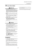
Page 88: ...ric shock may be caused H VXUH WR XVH WKH FRUG FODPSV DWWDFKHG WR WKH product R QRW GDPDJH RU VFUDWFK WKH FRQGXFWLYH FRUH and inner insulator of power and inter connecting wires when peeling them 8VH WKH SRZHU FRUG DQG QWHU FRQQHFWLQJ ZLUH of specified thickness type and protective devices required 1HYHU FRQQHFW 9 SRZHU WR WKH WHUPLQDO blocks etc for control wiring Otherwise the system will fail R...

Page 89: ... the central control communication wire Communication line Wired remote controller wiring This wiring is not required when using the supplied wireless remote controller RU ZLULQJ UHPRWH FRQWUROOHUV D FRUH QRQ SRODULW ZLUH PXVW EH XVHG CAUTION 7KH UHPRWH FRQWUROOHU ZLUH RPPXQLFDWLRQ OLQH DQG 9 ZLUHV FDQQRW EH SDUDOOHO WR FRQWDFW each other and cannot be stored in the same conduits If doing so a tro...

Page 90: ...1 U2 U3 U4 L1 L2 L3 N U5 U6 L N A B A B 380V 415V 50Hz 380V 60Hz U1 U2 U3 U4 L1 L2 L3 N U5 U6 U1 U2 L N A B A B U1 U2 L N A B A B U1 U2 L N A B Outdoor Power supply Earth terminal Earth terminal Outdoor Power supply Earth leakage breaker Earth leakage breaker Header outdoor unit Follower outdoor unit Control wiring between outdoor units Control wiring between indoor and outdoor units Control wirin...

Page 91: ...here is no problem if connections to indoor unit terminal blocks A and B are reversed Wiring diagram A B A B Terminal block for remote controller wiring of indoor unit Wired remote controller wire Procured locally Terminal block Wired remote controller unit 1111058602_EN indd 24 11 24 16 11 41 AM FILE NO SVM 17045 91 ...

Page 92: ...ntrol wire for this model 1 Remove the air inlet grille Open the air inlet grille upward and pull it toward you 2 Remove the terminal cover and the clamp base 3 Insert the power supply wire and control wire according to the local rule into the pipe hole on the wall 4 Take the power supply wire out of the cable slot on the rear panel so that it protrudes about 150mm from the front 5 Insert the cont...

Page 93: ...crew 7 Insert the power supply wire fully into the terminal block and secure it tightly with screws Tightening torque 1 2 N m 0 12 kgf m Secure the earth line with the earth screw 8 Clamp the power supply wire with the cord clamp 9 Insert the power supply wire fasten terminal of the flow selector unit into the power supply terminal Secure the earth line with the earth screw 10 Clamp the power supp...

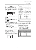
Page 94: ...as shipped from factory settings Changing of settings of for applicable controls Basic procedure for changing settings the former types of remote controller RBC Procedure 1 Push button and TEMP button simultaneously for at least 4 seconds After a while the display flashes as shown in the figure erase the display content and repeat the is pushed the indoor unit number wireless remote controller sub...

Page 95: ... lighting time of filter sign According to the installation condition the lighting time of the filter sign Notification of filter cleaning can be changed Follow to the basic operation procedure 1 2 3 4 5 6 For the CODE No in Procedure 3 specify 01 For the SET DATA in Procedure 4 select the SET DATA of filter sign lighting time from the following table To secure better effect of heating When it is ...

Page 96: ... D group control The wireless remote controller is unavailable for this control RU FDEOLQJ SURFHGXUH DQG FDEOHV RI WKH individual line Identical refrigerant line system refer to Electric work in this Manual DEOLQJ EHWZHHQ LQGRRU XQLWV LQ D JURXS LV performed in the following procedure RQQHFW WKH LQGRRU XQLWV E FRQQHFWLQJ WKH remote controller inter unit cables from the remote controller terminal b...

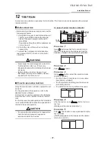
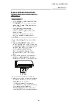
Page 97: ...GXUH RI WKH RSHUDWLRQ UHIHU WR WKH DWWDFKHG 2ZQHU V 0DQXDO IRUFHG WHVW UXQ FDQ EH H HFXWHG LQ WKH IROORZLQJ SURFHGXUH HYHQ LI WKH RSHUDWLRQ VWRSV E WKHUPR 2 Q RUGHU WR SUHYHQW D VHULDO RSHUDWLRQ WKH IRUFHG WHVW UXQ LV UHOHDVHG DIWHU PLQXWHV KDYH SDVVHG DQG returns to the usual operation CAUTION R QRW XVH WKH IRUFHG WHVW UXQ IRU FDVHV RWKHU than the test run because it applies an H FHVVLYH ORDG WR ...

Page 98: ...nd outdoor units 1 When pushing RESET button for 10 seconds or more Pi sound is heard and the operation changes to a forced cooling operation After approx 3 minutes a cooling operation starts forcedly Check cool air starts blowing If the operation does not start check wiring again 2 To stop a test operation push RESET button once again Approx 1 second The louver closes and the operation stops OPER...

Page 99: ...les The history can be confirmed from both operating status and stop status Procedure 1 When pushing and buttons at the same time for 4 seconds or more the following display appears If Service check is displayed the mode enters in the trouble history mode 01 Order of trouble history is displayed in CODE No window Check code is displayed in CHECK window Indoor unit address in which an error occurre...

Page 100: ... display Sensor block display of receiving unit Auxiliary code OPERATION TIMER PRE DEF Flash E01 Communication error between indoor and remote controller Detected at remote controller side Remote controller E02 Remote controller transmission error Remote controller E03 Communication error between indoor and remote controller Detected at indoor side Indoor E04 Communication circuit error between in...

Page 101: ...M error I F H01 H01 01 Comp 1 side 02 Comp 2 side Compressor break down IPDU H02 H02 01 Comp 1 side 02 Comp 2 side Magnet switch error Overcurrent relay operation Compressor trouble lock MG SW Overcurrent relay IPDU H03 H03 01 Comp 1 side 02 Comp 2 side Current detect circuit system error IPDU H04 H04 Comp 1 case thermo operation I F H06 H06 Low pressure protective operation I F H07 H07 Oil level ...

Page 102: ...P17 ALT Discharge temp TD2 error I F P19 P19 Detected outdoor unit number ALT 4 way valve inverse error I F P20 P20 ALT High pressure protective operation I F P22 P22 0 IGBT short 1 Fan motor position detective circuit error 3 Fan motor trouble C TH sensor temp error Heat sink overheat D TH sensor error E Vdc output error ALT Outdoor fan IPDU error IPDU P26 P26 01 Comp 1 side 02 Comp 2 side ALT G ...

Page 103: ...tioners is 0 3kg m NOTE 1 If there are 2 or more refrigerating systems in a single refrigerating device the amounts of refrigerant should be as charged in each independent device For the amount of charge in this example The possible amount of leaked refrigerant gas in rooms A B and C is 10kg The possible amount of leaked refrigerant gas in rooms D E and F is 15kg NOTE 2 The standards for minimum r...

Page 104: ...ILING 1 0001 HIGH CEILING 3 0003 Have you changed lighting time of filter sign If not fill check mark in NO CHANGE and fill check mark in ITEM if changed respectively For check method refer to Applicable controls in this sheet Filter sign lighting time CODE No 01 NO CHANGE NONE 0000 150H 0001 2500H 0002 5000H 0003 10000H 0004 Filter sign lighting time CODE No 01 NO CHANGE NONE 0000 150H 0001 2500H...

Page 105: ...not bring welding equipment near flammable objects Flames from the equipment may cause the flammable objects to catch fire If keeping the power on is absolutely unavoidable while doing a job such as inspecting the cir cuitry wear rubber gloves to avoid contact with the live parts Electric shocks may be received if the live parts are touched High voltage circuits are contained inside this unit Proc...

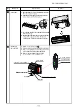
Page 106: ...lower part of the front panel then pull the upper part of the front panel toward you to remove it as shown on figure 3 4 1 Follow the procedure item 3 2 Remove screw holding the electric part cover 3 Take off the clamp base mounting screw and then remove the clamp base assembly 4 Take off fixing screws 2 pcs of PMV cover and then remove PMV cover Back body Front panel Hooks of front panel Screw Cl...

Page 107: ...TCJ sensors before removing because their shapes are reassembled 6 Remove the earth screw and earth line from evaporator 7 Disconnect the connectors for the fan motor louver motor and PMV motor from P C board assembly 8 Remove the 2 fixing screws that secures the electric parts box assembly unit display assembly and remove the electric parts box assembly Earth screw TC2 sensor TC1 sensor TCJ senso...

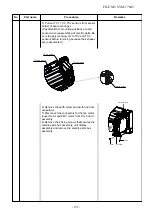
Page 108: ...the motor band and the fan motor outward 3 5 mm Cross flow fan Set screw Fan motor Body back Horizontal louver 6 1 Remove shaft of the horizontal louver from the back body First remove 2 the center shafts then remove the other shafts Horizontal louver Drain pan For ICF 340 30 6 To re installation Check the type name of fan motor Keep connector position and arrange fan motor wires follow figure 4 5...

Page 109: ...rs Louver motor connector P C board 5 Remove the drain pan from the back body To re installation Press the drain pan into the back body Please make sure ribs of drain pan in left and right side must be install to lock position Press the center arm of drain pan to back body Screw Unit display Drain pan Louver motor connector Drain pan Back body Drain pan Rib of drain pan Center arm of drain pan Bac...

Page 110: ...s flow fan is keep 3 5mm from closed wall of the main unit Holding the set screw install the cross flow fan so that flat area on shaft of the fan motor comes to the mounting hole of the set screw 4 Lift up the heat exchanger follow the figure Pull out the left hand side until the cross flow fan is released from the shaft of the fan motor and then pull out the lower side of heat exchanger follow th...

Page 111: ...ght side of the heat exchanger 4 Remove the pipe holder from the rear side of the main unit 5 Pull out the heat exchanger To re installation Please keep assembly heat exchanger follow figure as below Please make sure that the screw must be fix heat exchanger and motor cover 10 Heat exchanger Screws Screws Pipe holder Motor cover Screw Heat exchanger Motor cover Screw Heat exchanger FILE NO SVM 170...

Page 112: ...correctly by test operation Replacement procedure CASE 1 Before replacement power of the indoor unit can be turned on and the setup data can be readout by the wired remote controller Read EEPROM data see 1 Ø Replace service P C board power ON see 2 Ø Write the read data to EEPROM see 3 Ø Power reset If in group operation reset the power for all indoor units which are connected to the remote contro...

Page 113: ...x 1 minute is required to be able to use the remote controller 2 Replacement of service P C board 1 Replace the P C board with a service P C board In this time setting of jumper line cut or setting of DIP switch on the former P C board should be reflected on the service P C board Refer to the following table about DIP switch setting and drawing of P C board parts layout 2 It is necessary ti set in...

Page 114: ...rminator resistor for central control Remote controller A B selection Custom Multi model selection No use MMK AP 7H series 1 1 ON OFF At shipment OFF Without terminator OFF A selection ON Multi model OFF A B A B A B Indoor unit P C board Remote controller Group wire Group wire Case 1 Remove the group wire of the terminal blocks A and B of the changed indoor unit and then install the remote control...

Page 115: ... Repeat the above procedure 1 5 Using the set temperature button set 01 01 01 01 01 to the CODE No DN 2 Setup of lighting time of filter sign 6 The contents of the displayed setup data in this time should be agreed with the contents in the previous memorandum in 1 1 If data disagree change the displayed setup data to that in the previous memorandum by the timer time buttons and then push SET butto...

Page 116: ...on T10 Input selection T10 Sensor selection Timer set Wired remote controller Louver selection of cooling Memo Be sure to set as 0008 At shipment 0001 150 hour 0000 Standard 0099 Unfixed 0002 2 C 0000 Standard 0001 No auto mode Automatic selection cooling heating by connected 0000 Heat pump outdoor unit 0008 High wall type According to capacity type 0099 Unfixed 0099 Unfixed 0099 Unfixed 0003 3 de...

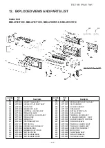
Page 117: ...215 43T39390 232 43T62365 216 43T39368 233 43T85681 217 43T39369 FRONT PANEL ASSY GRILLE OF AIR INLET ASSY AIR FILTER BACK BODY ASSY VERTICAL LOUVER ASSY DRAIN PAN ASSY HORIZONTAL LOUVER ASSY DRAIN HOSE DRAIN CAP STEPPING MOTOR MOTOR FAN CROSS FLOW FAN ASSY BASE BEARING BEARING ASSY MOLD MOTOR COVER MOTOR BAND BACK MOTOR BAND FRONT 234 43T39391 REFRIGERATION CYCLE ASSY FIX P SENSOR HOLDER SENSOR P...

Page 118: ...T21354 215 43T39390 232 43T62365 216 43T39368 233 43T85682 217 43T39369 FRONT PANEL ASSY GRILLE OF AIR INLET ASSY AIR FILTER BACK BODY ASSY VERTICAL LOUVER ASSY DRAIN PAN ASSY HORIZONTAL LOUVER ASSY DRAIN HOSE DRAIN CAP STEPPING MOTOR MOTOR FAN CROSS FLOW FAN ASSY BASE BEARING BEARING ASSY MOLD MOTOR COVER MOTOR BAND BACK MOTOR BAND FRONT 234 43T39391 REFRIGERATION CYCLE ASSY FIX P SENSOR HOLDER S...

Page 119: ...405 43T50304 402 43T60448 406 43T50317 403 43T60367 407 43T6V932 SENSOR HEAT EXCHANGER SENSOR HEAT EXCHANGER PC BOARD ASSY 404 43T6V674 PC BOARD ASSY TERMINAL TERMINAL 2P TEMPERATURE SENSOR Description Description Indoor Unit Part E FILE NO SVM 17045 119 ...

Page 120: ... air conditioners is 0 3 kg m3 NOTE 1 If there are 2 or more refrigerating systems in a single refrigerating device the amounts of refrigerant should be as charged in each independent device For the amount of charge in this example The possible amount of leaked refrigerant gas in rooms A B and C is 10 kg The possible amount of leaked refrigerant gas in rooms D E and F is 15 kg NOTE 2 The standards...

Page 121: ...TOSHIBA CARRIER THAILAND CO LTD 144 9 MOO 5 BANGKADI INDUSTRIAL PARK TIVANON ROAD TAMBOL BANGKADI AMPHUR MUANG PATHUMTHANI 12000 THAILAND ...

Reviews: