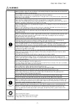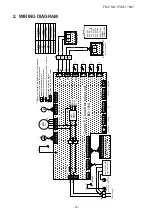
2. WIRING DIAGRAM
Control P.C board for indoor unit
(MCC-1696)
LM
DC12V
DC 7V
TA
DC15V
DC20V
P01
BLK
A
BLK
B
TC2
WIRED REMOTE CONTROLLER
(Sold separately)
RED
WHI
PNL/EMG
TCJ
OPTION
FAN DRIVE
1
3
5
CN67(BLK)
1
2
3
4
5
6
7
8
9
10
CN213(WHI)
F01
T3.15A 250VAC
2
1
3
CN80(GRN)
5
3
1
2
4
CN81(BLK)
5
3
1
2
4
6
CN60(WHI)
2
1
CN32(WHI)
2
1
CN104
(WHI)
(YEL)
2
1
CN102
1
2
CN101
(BLU)
3
1
2
(BRW)
CN100
3
2
1
(BLU)
CN41
5
3
1
2
4
CN50(WHI)
7
1
5
4
3
6
CN210(WHI)
MS
FM
CN33(WHI)
1
L
5
4
3
2
5
3
1
2
4
6
CN61(YEL)
5
M
N
1
3
4
5
6
2
8
7
9
TB01
A
B
TB02
-
+
+
-
U2
U1
6
1
3
4
5
2
CN82(BLU)
2
1
(BLU)
CN40
BLU
BLU
TC1
CN309(YEL)
1
3
Power supply
M
6
PMV
U1
U2
OUTDOOR UNIT
SUPPLY
CIRCUIT
POWER
INFRARED RAYS RECEIVE
AND INDICATION PARTS
(WP-033)
GRN & YEL
COLOR
IDENTIFICATION
Indoor temp sensor
TA
TC1,TC2,TCJ
TB01,
TB
02
Terminal Block
FM
F
01
LM
Fuse
Fan Motor
CN**
Symbol
Connector
Parts Name
indicates the control P.C. board.
1.Broken line indicate the wiring at site. Long dashed
short dashed line indicate the accessories.
2.
indicates the terminal block.
indicates the connection terminal.
indicates the connector on the control P.C. board.
indicates the protection ground.
4.
3.
GREEN&YELLOW
11
10
11
FLOW SELECTOR UNIT
(Sold separately)
5
3
1
2
4
CN521(RED)
OPTION
HA
HEAT EXCHANGER
BLK
5
Indoor unit
Earth screw
FS-unit
Earth screw
FILE NO. SVM-17045
- 15 -


