No.
13
14
15
Item
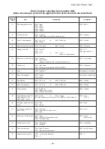
Filter sign display
(None in wireless type)
∗
Provided in the
separately laid type
TCB-AX21E2.
Operation standby
Heating standby
Selection of central
control mode
Outline of specifications
(1) The operation time of the indoor fan is integrated and
stored in memory, and the filter exchange signal is
sent to the remote controller to display on the remote
controller LCD after the specified time. (150H)
(2) When the filter reset signal is received form the remote
controller, time of the integrated timer is cleared. In this
time, if the specified time has passed, the measured
time is reset and LCD display disappears.
<Operation standby> ..
Displayed on wired remote controller
(1) When any of the DN codes listed below is displayed
• “P05” - Detection of an open phase in the power
supply wiring
• “P10” - Detection of indoor flooding in at least one
indoor unit
• “L30” - Detection of an interlock alarm in at least one
indoor unit
(2) Forced thermo OFF
• “COOL/DRY” operation is unavailable because at
least one indoor unit is operating in “HEAT” mode.
• “HEAT” operation is unavailable because at least one
indoor unit is operating in “COOL/DRY” mode under
priority cooling setting (bit 1 of SW11 on outdoor I/F
P.C. board ON).
(3) All indoor units not able to engage in any of the above
operations stand by in thermo OFF state.
(4) The indoor fan has been turned off because the
system is engaged in a heat refrigerant (oil) recovery
operation.
<Heating standby> ......
Displayed on wired remote controller
(1) Normal thermo OFF
• During heating, the indoor unit goes thermo OFF as
the heating temperature setting is reached.
(2) During heating, the fan rotates at a breeze speed
(UL or lower) or remains stationary to prevent cold air
from being discharged (including defrosting operation).
(3) Forced thermo OFF
• “HEAT” operation is unavailable because at least one
indoor unit is operating in “COOL/DRY” mode under
priority cooling setting (bit 1 of SW11 on outdoor I/F
P.C. board ON).
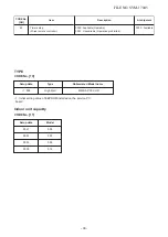
(1) The range of operations that can be performed via an
indoor unit remote controller can be determined
through the setting of the central controller.
(2) Setting details
TCC-Link central control
Operation via
TCC-Link
central
control
Individual
Central 1
Central 2
Central 3
Central 4
Operation via RBC-AMT32E
Start/stop
selection
{
×
×
{
{
Operation
mode
selection
{
{
×
×
×
Timer
setting
{
×
×
{
{
Temperature
setting
{
{
×
×
{
Fan
speed
setting
{
{
{
{
{
Air flow
direction
setting
{
{
{
{
{
RBC-
AMT32E
display
“CENTRAL
CONTROL IN
PROGRESS”
Remarks
• “OPERATION STANDBY
” displayed
No display provided on
wireless remote controller
• “HEATING STANDBY
”
displayed
• In the case of a wired
remote controller, “CEN-
TRAL CONTROL IN
PROGRESS
” is
displayed (lit up) while in
central control mode.
• The display blinks when a
control function
inaccessible to a remote
controller is chosen.
• A wireless remote
controller has the same set
of control functions,
although there is no
display.
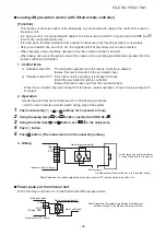
When a control operation
is performed via a wireless
remote controller while in
central control mode, a
peep sound alert (5 times)
is provided.
FILE NO. SVM-17045
- 21 -

