No.
Part name
P
rocedure
s
Remarks
Electric part
box assembly
4
1)
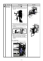
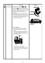
Follow the procedure item 3 .
2)
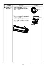
Remove screw holding the electric part cover
then remove fixing screw of base camp and
remove it.
3)
Disconnect the connectors for the fan motor
and louver motor from P.C.board assembly.
4) Remove the earth screw and earth line from
evaporator.
5) Pull out TC sensor and TCJ sensor from
sensor holder of the evaporator.
6) Remove TA sensor from the evaporator.
7) Remove the 2 fixing screws that secures the
electric parts box assembly, unit display
assembly and remove the electric parts box
assembly.
Earth screw
Earth line
Washer
TC sensor
or
TCJ sensor
Sensor holder
U3
U4
A
B
1
2
3
TA s
e
nsor
Earth line
TCJ sensor
(exists a
tube)
TC sensor
(no tube)
Fan motor
connector
Louver motor
connector
- The sensor, earth line must turn to down.
<To re-installation>
Base clamp
Screw
Screw
Electric part cover
Connectors
Screws
Unit display
Electric parts box
TCJ sensor
(exist a tube)
TA sensor
TC sensor
(no tube)
Earth line
- 114 -
Summary of Contents for MMK-AP0307HPUL
Page 15: ...3 WIRING DIAGRAM 15 ...

