Chec
k code
Wired remote
contr
oller
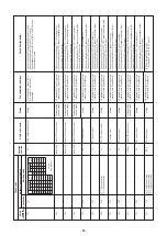
L05
L06
L07
L08
L09
L10
L20
L28
L29
L30
—
Outdoor 7-segment displa
y
Chec
k code
A
uxiliar
y
code
——
L06
No
. of indoor units with pr
ior
ity
——
L08
—
——
L10
—
——
L28
—
L29
L30
Detected indoor address
L31
—
Detected position
I/F
I/F
Indoor
Indoor
Indoor
I/F
TCC-Link
Indoor
I/F
I/F
Indoor
I/F
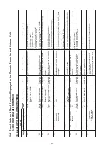
Chec
k code name
Duplicated indoor units with pr
ior
ity
(Displa
yed on indoor unit with pr
ior
ity)
Duplicated indoor units with pr
ior
ity
(Displa
yed on the unit other than
indoor unit with pr
ior
ity)
Group line in individual indoor unit.
Indoor group / address unset
Indoor capacity unset
Outdoor capacity unset
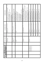
Duplicated centr
al control addresses
Quantity o
ver of connected outdoor
units
IPDU quantity error
Inter
loc
k in indoor unit from outside
Extended IC (Integr
ated Circuit) error
Status
All stop
All stop
Corresponding unit only stops
.
Corresponding unit only stops
.
Corresponding unit only stops
.
All stop
All stop
All stop
All stop
Corresponding unit only stops
.
Operation contin
ues
.
E
rr
or detection condition
Indoor units with pr
ior
ity w
ere
duplicated.
Indoor units with pr
ior
ity w
ere
duplicated.
At least one indoor unit connected to a group e
xisted in
the individual indoor units
.
Address w
as not y
et set up
.
Indoor unit capacity w
as unset.
On the I/F P
.C
. board f
or
ser
vice
, jumper line w
as not cut
according to the model.
Duplicated central control addresses
There were more than f
our
outdoor units
.
No
. of IPDU units detected
when po
w
er was tur
ned on
w
ere less
.
•
Outside error input ter
minal
Detected signal to (CN80) f
or
more 1 min
ute
P.
C
. board (I/F) par
ts error
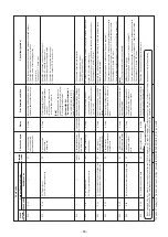
Chec
k item (position)
•
Chec
k displa
y of indoor unit with pr
ior
ity
.
•
Chec
k displa
y of indoor unit with pr
ior
ity and outdoor
unit.
•
Chec
k indoor address
.
•
Chec
k indoor address
.
Note)
After installation, this code is displa
yed when the po
w
er
is firstly tur
ned on.
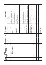
Set up indoor capacity
. (DN=11)
Chec
k model setup on outdoor I/F P
.C
. board A’
ssy f
or
ser
vice
.
•
Chec
k centr
al control address
.
•
Chec
k networ
k adaptor P
.C
. board.
(In case of
TCC-Link)
•
Chec
k No
. of connected outdoor units
.
(Max. 4 units per 1 system)
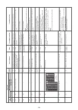
•
Chec
k communication line betw
een outdoor units
.
•
Chec
k outdoor P
.C
. board (I/F) error
.
•
Chec
k model setup f
or outdoor I/F ser
vice P
.C
. board.
•
Chec
k connection of U
A
R
T
communication connector
.
•
Chec
k Comp
. IPDU
, f
an IPDU
, and I/F P
.C
. board
error
.
Note)
U
A
R
T:
Univ
ersal Asynchronous Receiv
er
Tr
ansmitter
Outside de
vice is connected to connector (CN80):
1)
Chec
k outside de
vice error
.
2)
Chec
k indoor P
.C
. board error
.
Outside de
vice is not connected to connector (CN80):
1)
Chec
k indoor P
.C
. board error
.
Chec
k indoor (I/F) P
.C
. board.
A-3-IPDU
FA
N
A-3-IPDU
FA
N
12
3
IPDU
123
IPDU
01
{
0A
{{
02
{
0B
{{
{
03
{{
0C
{{
04
{
0D
{{
{
05
{{
0E
{{
{
06
{{
0F
{{
{
{
07
{{{
08
{
09
{{
{
mar
k:
Error position.
- 68 -
Summary of Contents for MMK-AP0307HPUL
Page 15: ...3 WIRING DIAGRAM 15 ...


