background image

 38 

38-EN

Installation Manual

13

TROUBLESHOOTING

A wired remote controller is necessary for this function. This function cannot be operate with a wireless 
remote controller.


„

 Con

fi

rmation and check

If a problem occurs with the air 
conditioner, the OFF timer indicator 
alternately shows the check code 
and the indoor Unit No. in which 
the problem occurred.

Check code

The indoor Unit No. in which 
the problem occurred.


„

 Troubleshooting history and con

fi

 rmation

You can check the troubleshooting history with the following procedure if a problem occurs with the air 
conditioner.
(The troubleshooting history records up to 4 incidents.)
You can check it during operation or when operation is stopped.
•  If you check the troubleshooting history during OFF timer operation, the OFF timer will be canceled.

Procedure

Description of operation

1

Push the OFF timer button for over 10 seconds and 
the indicators appear as an image indicating the 
troubleshooting history mode has been entered.
If [  Service check] is displayed, the mode enters in 
the troubleshooting history mode.
•  [01: Order of troubleshooting history] appears in 

the temperature indicator.

•  The OFF timer indicator alternately shows the 

[check code] and the [indoor Unit No.] in which the 
problem occurred.

2

Each time the setting button is pushed, the recorded 
troubleshooting history is displayed in sequence.
The troubleshooting history appears in order from 
[01] (newest) to [04] (oldest).

 CAUTION

In the troubleshooting history mode, DO NOT push 
the Menu button for over 10 seconds, doing so 
deletes the entire troubleshooting history of the 
indoor unit.

3

After you have 

fi

 nished checking, push the ON/OFF 

button to return to the regular mode.
•  If the air conditioner is operating, it remains 

operated even after the ON/OFF button has been 
pushed.
To stop its operation, push the ON/OFF button 
again.

Summary of Contents for MMK-UP0271HP-E

Page 1: ...Installation Manual Indoor Unit High Wall Type Model name MMK UP0271HP E MMK UP0301HP E MMK UP0361HP E Installation Manual 1 English AIR CONDITIONER MULTI TYPE For commercial use ...

Page 2: ...he ozone layer Information If U series models TU2C Link are combined with models other than U series TCC Link the wiring specifications and maximum number of connectable indoor units will be changed Pay attentions to their communication specifications when carrying out the installation maintenance or repair For its details refer to the Electrical connection in this Manual Contents 1 PRECAUTIONS FO...

Page 3: ...tion or alternatively he or she has been instructed in such matters by an individual or individuals who have been trained and is thus thoroughly acquainted with the knowledge related to this work The qualified installer who is allowed to work at heights has been trained in matters relating to working at heights with the air conditioners made by Toshiba Carrier Corporation or alternatively he or sh...

Page 4: ...ese safety cautions describe important matters concerning safety to prevent injury to users or other people and damages to property Please read through this manual after understanding the contents below meanings of indications and be sure to follow the description Indication Meaning of Indication WARNING Text set off in this manner indicates that failure to adhere to the directions in the warning ...

Page 5: ...ving parts Do not operate unit with grille removed Stop the unit before the servicing CAUTION High temperature parts You might get burned when removing this panel CAUTION High temperature parts You might get burned when removing this panel CAUTION Do not touch the aluminum fins of the unit Doing so may result in injury CAUTION Do not touch the aluminium fins of the unit Doing so may result in inju...

Page 6: ...allowed to do installation work Inappropriate installation may result in water leakage electric shock or fire Do not use any refrigerant different from the one specifled for complement or replacement Otherwise abnormally high pressure may be generated in the refrigeration cycle which may result in a failure or explosion of the product or an injury to your body Before opening the front panel of the...

Page 7: ...rk location before proceeding with the work Parts and other objects may fall from above possibly injuring a person below While carrying out the work wear a helmet for protection from falling objects Do not use the refrigerant other than R410A For the refrigerant type check the outdoor unit to be combined The refrigerant used by this air conditioner follow to the outdoor unit The air conditioner mu...

Page 8: ... topple over or give rise to noise vibration water leakage or other trouble Carry out the specied installation work to guard against the possibility of high winds and earthquake If the air conditioner is not installed appropriately a unit may topple over or fall down causing an accident If refrigerant gas has leaked during the installation work ventilate the room immediately If the leaked refriger...

Page 9: ...his protective gear may result in electric shocks Use wiring that meets the specifications in the Installation Manual and the stipulations in the local regulations and laws Use of wiring which does not meet the specifications may give rise to electric shocks electrical leakage smoking and or a fire Connect earth wire grounding work Incomplete grounding causes an electric shock Do not connect earth...

Page 10: ...the installation work check for refrigerant leaks and check the insulation resistance and water drainage Then conduct a test run to check that the air conditioner is operating properly Explanations given to user Upon completion of the installation work tell the user where the circuit breaker is located If the user does not know where the circuit breaker is he or she will not be able to turn it off...

Page 11: ...he main unit and installation tools are changed from those for the conventional refrigerant Accordingly the exclusive tools are required for the new refrigerant R410A For connecting pipes use new and clean piping designed for R410A and please care so that water or dust does not enter To disconnect the appliance from main power supply This appliance must be connected to the main power supply by mea...

Page 12: ...l please refer to the enclosed CD R Owner s Manual 1 Hand over to customers For other languages that do not appear in this installation Manual please refer to the enclosed CD R CD ROM 1 Owner s Manual and Installation Manual Installation plate 1 Wireless remote controller 1 Battery 2 Remote controller holder 1 Mounting screw Ø4 25R 6 Flat head wood screw Ø3 1 16R 2 Screw Ø4 10R 3 Heat insulator 1 ...

Page 13: ...here vapors from food oils are formed such as kitchens where food oils are used Blocked filters may cause the air conditioner s performance to deteriorate condensation to form the plastic parts to be damaged and other such problems to result Locations near obstructions such as ventilation openings or lighting fixtures where the flow of the blown air will be disrupted a disruption of the air flow m...

Page 14: ...ck Make sure to run the drain hose sloped downward Cut the piping hole sloped slightly Refrigerant piping must be protected from physical damage Install a plastic cover or equivalent Before installing the wireless remote controller 1 Remove the battery cover 2 Insert 2 new batteries R03 AAA type following the and positions Wireless remote controller Cover Batteries Hook Installation space The indo...

Page 15: ...gnal from the indoor unit Do not install the remote controller in a place exposed to direct sunlight or close to a heating source such as a stove Keep the remote controller at least 1 m apart from the nearest TV set or stereo equipment This is necessary to prevent image disturb bounces or noise interference The location of the remote controller should be determined as shown below Indoor unit Side ...

Page 16: ...are packaged Carry in the indoor unit as it is packaged if possible If carrying in the indoor unit unpacked by necessity be sure to use buffering cloth etc to not damage the unit To move the indoor unit do not apply force to the refrigerant pipe drain pan foamed parts or resin parts etc Carry the package by two or more persons and do not bundle it with plastic band at positions other than specifie...

Page 17: ... fit the installation plate onto the wall by screwing it in the upper and lower parts to hook up the indoor unit 2 To mount the installation plate on a concrete wall with anchor bolts utilize the anchor bolt holes as illustrated in the above figure 3 Install the installation plate horizontally in the wall CAUTION When installing the installation plate with a mounting screw do not use the anchor bo...

Page 18: ...slit on the bottom left or right side of the front panel for the bottom left or right connection with a pair of nippers 2 Changing drain hose For leftward connection bottom leftward connection and rear leftward connection s piping it is necessary to change the drain hose and drain cap How to remove the drain hose The drain hose can be removed by removing the screw securing the drain hose and then ...

Page 19: ... drain cap Application causes deterioration and drain leakage from the plug CAUTION Firmly insert the drain hose and drain cap otherwise water may leak How to remove the drain hose 1 Remove the front panel 2 Remove the screws of drain hose 3 Pull out the drain hose How to fix the drain hose 1 Put the drain hose 2 Screw the drain hose to the indoor unit 3 Install the front panel T In case of right ...

Page 20: ...n the wall When bending the connecting pipe make sure to use a spring bender so as not to crush the pipe Bend the connecting pipe within a radius of 30 mm To connect the pipe after installation of the unit figure 545 mm Liquid side To the forefront of flare 645 mm Gas side Outward of indoor unit 43 mm R 30 mm Use polisin polyethylene core or the like for bending pipe Use the handle of screwdriver ...

Page 21: ...pes make sure the slit aperture toward the ceiling surface CAUTION Bind the auxiliary pipes two and power supply wiring and control wiring with facing tape tightly In case of leftward piping and rear leftward piping bind the auxiliary pipes two only with facing tape Indoor unit Power supply wiring Control wiring Auxiliary pipes Installation plate Carefully arrange pipes so that any pipe does not s...

Page 22: ... installation plate Especially when the pipes are pulled out from the left side the unit must be screwed to the installation plate Lid screws Screws 1 Run the drain hose sloped downwards NOTE Hole should be made at a slight downward slant on the outdoor side 2 Put water in the drain pan and make sure that the water is drained out of doors 3 When connecting extension drain hose insulate the connect...

Page 23: ...nit 3 Evacuate the air in the connecting pipes by using VACUUM PUMP 4 Check the gas leakage Connected points Pipe size dia mm MMK PIPE SIZE mm Gas side Liquid side UP027 to UP036 type 15 9 9 5 Permissible Piping Length and Height Difference They vary according to the outdoor unit For details refer to the Installation Manual attached to the outdoor unit Flaring ෬ Cut the pipe with a pipe cutter Rem...

Page 24: ... leak check follow the Installation Manual attached to the outdoor unit CAUTION Do not scratch the inner surface of the flared part when removing burrs Flare processing under the condition of scratches on the inner surface of flare processing part will cause refrigerant gas leak Check that the flared part is not scratched deformed stepped or flattened and that there are no chips adhered or other p...

Page 25: ...rollers for the respective air conditioners when the 2 air conditioners are closely installed Wireless remote controller B setup 1 Push RESET button on the indoor unit to turn the air conditioner ON 2 Point the wireless remote controller at the indoor unit 3 Push and hold button on the wireless remote controller by the tip of the pencil 00 will be shown on the display 4 Push during pushing B will ...

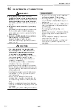
Page 26: ...eakage breaker is not installed an electric shock may be caused Use the cord clamps attached to the product Do not damage or scratch the conductive core and inner insulator of power and control wires when peeling them Use the power supply wire and control wires of specified thickness type and protective devices required Do not connect 208 240V power to the terminal blocks Uv U1 Uv U2 A B for contr...

Page 27: ...ated total current values of the indoor units Power supply wiring Below 50 m 2 5 mm2 Control wiring Central controller wiring Use a 2 core non polarity wire To prevent any possible noise issues use a shielded 2 core wire The total stated length of communication wiring is determined by the interconnecting length of indoor to outdoor wire plus the length of the central control communication wire T C...

Page 28: ...tral control line Uc line Between outdoor and outdoor units Uv line and Uc line are independent from another refrigerant line Total length of Uv and Uc lines L3 L4 in each refrigerant line is up to 1000 m U3 U4 Uh U1 U2 Uv A B U1 U2 Uv A B U1 U2 Uv A B U1 U2 Uv A B U2 Uv U5 U6 Uc U3 U4 Uh U1 U2 Uv U5 U6 Uc U3 U4 Uh U1 U2 Uv U5 U6 Uc U3 U4 Uh U1 Central control device Remote controller Outdoor unit...

Page 29: ... size 1 25 to 2 0 mm Up to 100 m The length of the communication line L1 L2 L3 means the total length of the inter unit wire length between indoor and outdoor units added with the central control system wire length Central control device Remote controller Outdoor unit Indoor unit U series U series U3 U4 U1 U2 A B U1 U2 A B U1 U2 A B U1 U2 A B U2 U5 U6 U3 U4 U1 U2 U5 U6 U3 U4 U1 U2 U5 U6 U3 U4 U1 U...

Page 30: ...L2 Ln Up to 200 m CAUTION The remote controller wire Communication line and AC 208 240V wires cannot be parallel to contact each other and cannot be stored in the same conduits If doing so a trouble may be caused on the control system due to noise or other factor If U series models TU2C Link are combined with models other than U series TCC Link the wiring specifications and maximum number of conne...

Page 31: ...door Outdoor unit Follower outdoor Control wiring between outdoor units Shield wire Control wiring between indoor and outdoor units Shield wire Control wiring between indoor units Shield wire Indoor power supply 220V 240V 50 Hz 208V 230V 60 Hz Circuit breaker Power switch Pull box Pull box Group control Remote controller Remote controller Remote controller Pull box Address setup Set up the address...

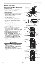
Page 32: ...e it tightly with screws Tightening torque 1 2 N m 0 12 kgf m Secure the earth line with the earth screw 9 Clamp the power supply wire with the cord clamp 10 Attach the terminal cover and the air inlet grille to the indoor unit CAUTION Be sure to refer to the wiring diagram attached inside the front panel Check local electrical cords an also any specific wiring instructions and limitations Do not ...

Page 33: ...amp base with a screw 7 Insert the power supply wire fully into the terminal block and secure it tightly with screws Tightening torque 1 2 N m 0 12 kgf m Secure the earth line with the earth screw 8 Clamp the power supply wire with the cord clamp 9 Insert the power supply wire fasten terminal of the flow selector unit into the power supply terminal Secure the earth line with the earth screw 10 Cla...

Page 34: ...emote controller and simple remote controller by itself so install a wired remote controller separately as well Applicable controls setup settings at the site Remote controller model name RBC ASCU11 E Basic procedure Be sure to stop the air conditioner before making settings Change the setup while the air conditioner is not working CAUTION Set only the Code No shown in the following table Do NOT s...

Page 35: ...ed Follow to the basic operation procedure 1 2 3 4 5 6 For the CODE No in Procedure 4 specify 01 For the SET DATA in Procedure 5 select the SET DATA of filter sign lighting time from the following table SET DATA Filter sign lighting time 0000 None 0001 150H Factory setting 0002 2500H 0003 5000H 0004 10000H To secure better effect of heating When it is difficult to obtain satisfactory heating due t...

Page 36: ...oup control The wireless remote controller is unavailable for this control For cabling procedure and cables of the individual line Identical refrigerant line system refer to Electrical connection in this Manual Cabling between indoor units in a group is performed in the following procedure Connect the indoor units by connecting the remote controller inter unit cables from the remote controller ter...

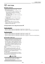
Page 37: ...thod be sure to release the short circuit of CN72 after the test run is completed Operate the unit with the remote controller as usual For the procedure of the operation refer to the Owner s Manual attached to the outdoor unit A forced test run can be executed in the following procedure even if the operation stops by thermostat OFF In order to prevent a serial operation the forced test run is rele...

Page 38: ...low the Owner s Manual Finish the forced cooling operation in a short time because it applies excessive strength to the air conditioner A test operation of forced heating is unavailable Perform a test operation by heating operation using the switches of the remote controller However heating operation may be not carried out according to the temperature conditions Check wiring piping of indoor and o...

Page 39: ...n of operation 1 Push the OFF timer button for over 10 seconds and the indicators appear as an image indicating the troubleshooting history mode has been entered If Service check is displayed the mode enters in the troubleshooting history mode 01 Order of troubleshooting history appears in the temperature indicator The OFF timer indicator alternately shows the check code and the indoor Unit No in ...

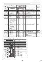
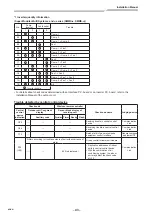
Page 40: ...play of receiving unit Auxiliary code Operation Timer Ready Flash E01 Communication trouble between indoor unit and remote controller Detected at remote controller side Remote controller E02 Remote controller transmission trouble Remote controller E03 Communication trouble between indoor unit and remote controller Detected at indoor unit side Indoor unit E04 Communication circuit trouble between i...

Page 41: ...06 01 TE1 sensor 02 TE2 sensor 03 TE3 sensor ALT TE1 TE2 or TE3 sensor trouble I F F07 F07 01 TL1 sensor 02 TL2 sensor 03 TL3 sensor ALT TL1 TL2 or TL3 sensor trouble I F F08 F08 ALT TO sensor trouble I F F09 F09 01 TG1 sensor 02 TG2 sensor 03 TG3 sensor ALT TG1 TG2 or TG3 sensor trouble I F F10 ALT Indoor unit TA sensor trouble Indoor unit F11 ALT TF sensor trouble Indoor unit F12 F12 01 TS1 sens...

Page 42: ...rity SIM Duplicated indoor units with priority Displayed in unit other than indoor unit with priority I F L07 SIM Group line in individual indoor unit Indoor unit L08 L08 SIM Indoor unit group Address unset Indoor unit I F L09 SIM Indoor unit capacity unset Indoor unit L10 L10 SIM Outdoor unit capacity unset I F L17 L17 SIM Outdoor unit type mismatch trouble I F L18 L18 SIM Flow selector unit trou...

Page 43: ...2 Input current sensor trouble 3 Motor lock trouble C Sensor temperature trouble No TH sensor 4 Motor current trouble D Sensor short circuit release trouble No TH sensor 5 Synchronization step out trouble Put in Fan Inverter No in mark ALT Outdoor unit fan inverter trouble Inverter P26 P26 01 Comp 1 side 02 Comp 2 side 03 Comp 3 side ALT IPM short protection trouble Inverter P29 P29 01 Comp 1 side...

Page 44: ...d by central control device Check code Wireless remote controller Check code name Judging device Central control device indication Outdoor unit 7 segment display Sensor block display of receiving unit Auxiliary code Operation Timer Ready Flash C05 Sending trouble in central control device Communication Link C06 Receiving trouble in central control device Communication Link C12 Batch alarm of gener...

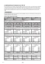
Page 45: ...tion limit kg m3 The concentration limit of R410A which is used in multi air conditioners is 0 3 kg m3 T NOTE 1 If there are 2 or more refrigerating systems in a single refrigerating device the amounts of refrigerant should be as charged in each independent device e g charged amount 10 kg Outdoor unit e g charged amount 15 kg Indoor unit Room A Room B Room C Room D Room E Room F For the amount of ...

Page 46: ...CHANGE STANDARD HIGH CEILING 1 HIGH CEILING 3 0000 0001 0003 Have you changed lighting time of filter sign If not fill check mark x in NO CHANGE and fill check mark x in ITEM if changed respectively For check method refer to Applicable controls in this sheet Filter sign lighting time CODE No 01 Filter sign lighting time CODE No 01 Filter sign lighting time CODE No 01 Filter sign lighting time CODE...

Page 47: ...144 9 Moo 5 Bangkadi Industrial Park Tivanon Road Tambol Bangkadi Amphur Muang Pathumthani 12000 Thailand 1130550199 ...

Reviews: