background image

10

ELECTRICAL CONNECTION


WARNING

1. Using the speci

fi

 ed wires, ensure to connect

the wires, and 

fi

 x wires securely so that the

external tension to the wires do not affect
the connecting part of the terminals.

Incomplete connection or 

fi

 xation may cause a

fi

 re, etc.

2. Be sure to connect earth wire. (grounding

work)

Incomplete grounding cause an electric shock.
Do not connect ground wires to gas pipes,
water pipes, lightning rods or ground wires for
telephone wires.

3. Appliance shall be installed in accordance

with national wiring regulations.

Capacity shortage of power circuit or
incomplete installation may cause an electric
shock or a 

fi

 re.


CAUTION

For communication line, use wires with
the same type and size. If each wire has a
different type and size from another one,
it will cause a communication trouble.

• If incorrect / incomplete wiring is carried out,

it will cause an electrical 

fi

 re or smoke.

• Install an earth leakage breaker that is not

tripped by shock waves.
If an earth leakage breaker is not installed,
an electric shock may be caused.

• Use the cord clamps attached to the product.
• Do not damage or scratch the conductive core

and inner insulator of power and control wires
when peeling them.

• Use the power supply wire and control wires

of speci

fi

 ed thickness, type, and protective

devices required.

• Do not connect 208-240V power to the terminal

blocks (Uv (U1)), (Uv (U2)), (A), (B) for control
wiring. (Otherwise, the system will fail.)

• Perform the electric wiring so that it does not

come to contact with the high-temperature part
of the pipe.
The coating may melt resulting in an accident.

REQUIREMENT

• For power supply wiring, strictly conform to

the Local Regulation in each country.

• For wiring of power supply of the outdoor

units, follow the Installation Manual of each
outdoor unit.

• Perform the electric wiring so that it does not

come to contact with the high-temperature
part of the pipe.
The coating may melt resulting in an
accident.

• After connecting wires to the terminal blocks,

provide a trap and fix wires with the cord
clamp.

• Run the refrigerant piping line and control

wiring line in the same line.

• Do not turn on the power of the indoor unit

until vacuuming of the refrigerant pipes
completes.

BOOK_1130550101_EN.indd   25

BOOK_1130550101_EN.indd   25

11/2/2564 BE 19:18

11/2/2564 BE   19:18


- 110 -

Summary of Contents for MMK- UP0301HP Series

Page 1: ...R410A SERVICE MANUAL MULT TYPE High Wall Types MMK UP0271HP Series MMK UP0301HP Series MMK UP0361HP Series Revised on April 2021 FILE NO SVM 21033 1 ...

Page 2: ...TS RATING 17 4 REFRIGERANTING CYCLE DIAGRAM 18 5 CONTROL OUTLINE 19 6 CONFIGURATION OF CONTROL CIRCUIT 25 7 APPLIED CONTROL 33 8 TROUBLESHOOTING 58 9 INSTALLATION MANUAL 86 10 12 REPLACEMENT OF P C BOARD FOR INDOOR UNIT SERVICING 140 13 EXPLODED VIEWS AND PARTS LIST 144 HOW TO REPLACE MAIN PARTS 131 11 SPECIFICATIONS 14 2 ...

Page 3: ...ho have been trained and is thus thoroughly acquainted with the knowledge related to this work The qualified installer who is allowed to work at heights has been trained in matters relating to working at heights with the air conditioners made by Toshiba Carrier Corporation or alternatively he or she has been instructed in such matters by an individual or individuals who have been trained and is th...

Page 4: ...on for electricians and from heat Insulating shoes Clothing to provide protection from electric shock Helmets for use in industry Shoes with additional protective toe cap Gloves to provide protection for electricians and from heat Indication DANGER WARNING CAUTION Explanation Indicates contents assumed that an imminent danger causing a death or serious injury of the repair engineers and the third ...

Page 5: ...ns of the unit Doing so may result in injury CAUTION BURST HAZARD Open the service valves before the operation otherwise there might be the burst CAUTION Do not climb onto the fan guard Doing so may result in injury Description WARNING ELECTRICAL SHOCK HAZARD Disconnect all remote electric power supplies before servicing WARNING Moving parts Do not operate unit with grille removed Stop the unit be...

Page 6: ... OFF position and contact a qualified service person Take steps to ensure that the power will not be turned on by marking out of service near the circuit breaker for instance until qualified service person arrives Continuing to use the air conditioner in the trouble status may cause mechanical problems to escalate or result in electric shocks or other failure When you access inside of the service ...

Page 7: ...h complies with the ISO 14122 standard and follow the procedure in the ladder s instructions Also wear a helmet for use in industry as protective gear to undertake the work When working at heights put a sign in place so that no one will approach the work location before proceeding with the work Parts and other objects may fall from above possibly injuring a person below When executing address sett...

Page 8: ...rent types of refrigerant are mixed abnormal high pressure generates in the refrigerating cycle and an injury due to breakage may be caused When the air conditioner has been installed or relocated follow the instructions in the Installation Manual and purge the air completely so that no gases other than the refrigerant will be mixed in the refrigerating cycle Failure to purge the air completely ma...

Page 9: ...alve is opened Running the compressor under condition that the valve closes causes an abnormal high pressure resulted in damage of the parts of the compressor and etc and moreover if there is leak of refrigerant at connecting section of pipes the air is sucked and causes further abnormal high pressure resulted in burst or injury Only a qualified installer 1 or qualified service person 1 is allowed...

Page 10: ...structions to install the air conditioner Be sure to use the company specified products for the separately purchased parts Use of non specified products may result in fire electric shock water leakage or other failure Have the installation performed by a qualified installer Do not supply power from the power terminal block equipped on the outdoor unit to another outdoor unit Capacity overflow may ...

Page 11: ...ers do not mix in because pipes are affected by impurities such as water oxide scales oil etc Use the clean pipes Be sure to brazing with flowing nitrogen gas Never use gas other than nitrogen gas 4 For the earth protection use a vacuum pump for air purge 5 R410A refrigerant is azeotropic mixture type refrigerant Therefore use liquid type to charge the refriger ant If using gas for charging compos...

Page 12: ... etc Vacuum evacuating Refrigerant charge Refrigerant charge Gas leakage check Refrigerant charge R410A air conditioner installation Existence of Whether conven new equipment tional equipment for R410A can be used Yes Note 1 Yes Note 1 Yes No Yesa No Yes No Yes Yes Yes No Yes No Note 2 No Conventional air conditioner installation Whether new equipment can be used with conventional refrigerant Yes ...

Page 13: ...cifications Model Sound pressure level dBA Cooling Heating Weight kg Main unit MMK UP0271HP E MMK UP0301HP E MMK UP0361HP E 21 21 21 Under 70 dBA MMK UP0271HP TR MMK UP0301HP TR MMK UP0361HP TR 21 21 21 13 ...

Page 14: ...nd power level H M L dBA Gas side mm Liquid mm Drain port mm MMK UP0271HP E TR MMK UP0301HP E TR MMK UP0361HP E TR 8 00 9 00 10 00 9 00 10 00 11 20 Electrical characteristics Running current 0 30 0 46 0 56 Starting current 0 34 0 50 0 60 Power consumption 0 034 0 054 0 066 Outer diamension Main unit 350 350 350 Ceiling panel Appearance Main unit 1200 1200 1200 Ceiling panel 280 280 280 Total weigh...

Page 15: ... Air filter Remote control holder Wireless remote control 348 280 49 50 72 172 57 5 Front panel The outside diameter of thermal insulation 74 7 5 1092 348 380 380 1200 515 515 123 or more 85 38 61 or more 38 φ 8 0 φ 1 0 0 50 10 23 24 57 or more 50 7 Horizonal airflow louver 250 176 Bushing knock out 20 NP At the time of operation Hook part of an installation plate 760 Distance to surface of wall D...

Page 16: ...3 WIRING DIAGRAM 16 ...
Page 17: ...Ω at 25 C 10kΩ at 25 C n Name of Each Part 3 4 1 2 5 6 7 8 9 10 11 1 Air inlet grille 2 Air filter 3 Room temperature sensor 4 Front panel 5 Air outlet 6 Horizontal louver Front 7 Horizontal louver Back 8 Vertical louver For change horizontal air flow direction adjust manually 9 Display panel 10 Infrared signal receiver 11 Earth screw provided in the electric parts box For change vertical air flow...

Page 18: ...in cooling operation 2 Controls under cool in heating operation 3 Recovers refrigerant oil in cooling operation 4 Recovers refrigerant oil in heating operation Connector CN104 2P White 1 Detects indoor suction temperature Connector CN100 3P Brown 1 Controls PMV super heat in cooling operation Connector CN101 2P Blue 1 Controls PMV under cool in heating operation Connector CN102 2P Yellow 1 Control...

Page 19: ...ernative flashing change the mode on the wireless remote controller 1 Adjustment range Set temperature on remote controller C 2 From the item code 06 the setup temperature in heating operation can be corrected Setup at shipment 1 Based upon difference between Ta and Ts the operation frequency of the outdoor unit varies 1 By the command from the remote controller HIGH HH MED H or LOW L AUTO operati...

Page 20: ...nua tion of J zone operation of the the indoor fan in LOW L mode until it reaches the I I I I I zone It is reset when the following conditions are satisfied Reset conditions 1 TC1 12 C and TC2 12 C and TCJ 12 C 2 20 minutes passed after stop 2 In cooling operation the air conditioner operates as described below based upon temp detected by TC2 and TCJ sensors When M zone is detected for 45 minutes ...

Page 21: ... reading The timing of termination is deter mined by each indoor unit 1 For 5 minutes after the operation has started the operation is continued even if entering thermostat OFF condition 2 However Cooling Heating exchange and the system protective control precede and thermostat is OFF 1 When the air conditioner stops in the HEAT mode drive the indoor fan with LOW mode for approx 30 seconds 1 Flap ...

Page 22: ...nt oil recovery operation Heating standby Displayed on wired remote controller 1 Normal thermo OFF During heating the indoor unit goes thermo OFF as the heating temperature setting is reached 2 During heating the fan rotates at a breeze speed UL or lower or remains stationary to prevent cold air from being discharged including defrosting operation 3 Forced thermo OFF HEAT operation is unavailable ...

Page 23: ...temperature Only when the fan speed before the Hi POWER operation is not high the fan speed will be increased When you press the ECO button during cooling heating or A operation the air conditioner will start the following operation The fan speed display will indicate AUTO and low speed will be used Cooling operation In the operation suppression zone where capacity is kept to the minimum overcooli...

Page 24: ...operation stop the operation mode change and the resetting of power supply Therefore the operation at the next time also will be activated with Save operation is valid Remarks Check code P12 RBC AMT32E SWING FAN FIX QUIET COMFORT SLEEP 1 Hi POWER To operate the air conditioner with the setting memorized 1 Press the PRESET button The setting memorized will be indicated and the air conditioner opera...

Page 25: ... LED LCD driver CPU Central control communication circuit Remote controller communication circuit Display LED Receiver unit Driver Function setup Key switch Power circuit Power circuit DC280V DC15V Fan motor control circuit EEPROM TA sensor TC1 TC2 sensor TCJ sensor HA Run Alarm Ready Thermo ON COOL HEAT FAN Wireless remote signal setting A B Central control remote controller Sold separately AC sy...

Page 26: ...utside output Central control communication circuit Remote controller communication circuit Display LED Receiver unit Driver Power circuit DC280V DC15V Fan motor control circuit EEPROM TA sensor TC sensor TCJ sensor HA Run Warning Defrost Thermo ON COOL HEAT FAN Bus communication circuit Wireless remote signal setting A B Central control remote controller Sold separately AC synchronous signal inpu...

Page 27: ...r CN102 Yellow TA Sensor CN104 White TC2 Sensor CN101 Black Float SW CN34 Red TC1 Sensor CN100 Brown DISP N72 White CHK CN71 White EEPROM IC503 Option power supply CN309 Yellow Power supply CN67 Black DC fan motor CN210 White Louver CN33 White PMV Output CN82 Blue Output FS Unit CN81 Black Ventilation output CN32 White HA T10 CN61 Yellow 27 ...

Page 28: ...1 ON OFF input 0V㧔COM㧕 Remote controller prohibited input Operation output Open collector DC12V㧔COM Warning output Open collector HA ON OFF input J01 YES NO Pulse At shipment from factory Static input selection Permission Prohibition of remote controller operation stop is performed by input Operation ON Answer back of HA Warning output ON Check mode input 0V This check is used to check indoor oper...

Page 29: ... Procedure 1 Push TEST button to clear the TEST mode TEST display in the display part disappears and status becomes the normal stop status TEMP ON OFF SET TIME TIMER SET TEST FILTER RESET CL FAN SAVE SWING FIX VENT MODE UNIT LOUVER 1 5 2 4 3 TEST TEST RBC AMT In case of wired remote controller Note The test run returns to the normal operation after 60 minutes 7 3 Test run of indoor unit Cooling He...

Page 30: ...ay part and the test run is permitted 2 Push ON OFF button 3 Push menu button to select the operation mode Select Cool or Heat with setting button Do not run the air conditioner in a mode other than Cool or Heat The temperature setting function does not work during test run The check code is displayed as usual 4 After the test run push OFF timer button to stop a test run TEST disappears on the dis...

Page 31: ...ns After confirming a signal receiving sound beep immediately set the temperature to 29 C with the temp setup buttons Cooling test run Heating test run After confirming a signal receiving sound beep immediately set the temperature to 17 C with the temp setup buttons After confirming a signal receiving sound beep immediately set the temperature to 30 C with the temp setup buttons 4 5 6 Repeat proce...

Page 32: ...tion to short circuit of CHK pin CN71 on the indoor P C board the minimum opening degree 30 pls can be set to the indoor PMV only When open DISP pin the maximum opening degree 1500 pls can be obtained again For the detailed positions of CHK pin CN71 on indoor P C board and DISP pin CN72 on indoor P C board refer to the indoor P C board How to clear Open CHK pin While the system is operating it sto...

Page 33: ... the system returns to normal off state TEMP ON OFF SET TIME TEST FILTER RESET CL SAVE SWING FIX VENT UNIT LOUVER CODE No UNIT No R C No TIMER SET MODE FAN SETDATA TEST SETTING 00 01 1 1 10 5 4 1 2 6 3 RBC ASCU11 3 6 4 5 1 7 2 4 5 Indoor unit No 1 Push and hold menu button and setting button simultaneously for 10 seconds or more After a while the display flashes as shown in the figure ALL is displ...

Page 34: ...e selected indoor unit repeat from Procedure 4 7 When all the settings have been completed push ON OFF button to finish the settings Return to the normal mode SETTING flashes and then the display content disappears and the air conditioner enters the normal stop mode The remote controller is unavailable while SETTING is flashing To change settings of another indoor unit repeat from Procedure 1 3 Pu...

Page 35: ...it to 0064 No 30 unit TCC LINK 00Un 0099 Unfixed 1 0001 No 1 unit to 0128 No 128 unit TU2C LINK 00Un Unfixed When using U series remote controller 0099 Unfixed Other than U series remote controller Indoor unit address 0001 No 1 unit to 0064 No 64 unit TCC LINK 00Un 0099 Unfixed 1 0001 No 1 unit to 0128 No 128 unit TU2C LINK 00Un Unfixed When using U series remote controller 0099 Unfixed Other than...

Page 36: ...ycle swing Louver fixed position 0000 Release 0001 Horizontal discharge position 0000 Not fixed Louver No 1 0005 Downward discharge position Louver fixed position 0000 Release 0001 Horizontal discharge position 0000 Not fixed Louver No 2 0005 Downward discharge position Louver fixed position 0000 Release 0001 Horizontal discharge position 0000 Not fixed Louver No 3 0005 Downward discharge position...

Page 37: ...ller use is impossible 0000 No central device control 103 Remote controller 0000䋺Use 0001䋺Do not use 0000㧦Use 1 Display order of 00Un and 0099 varies depending on remote controller models or communication types 2 Communication protocol can be automatically switched with the setup in the outdoor unit during installation For Central control address DN 03 Indoor unit address DN 13 FS unit address DN ...

Page 38: ...Type DN code 10 Value Type Model 08 High Wall MMK UP0271 0301 0361 Value Capacity 12 0271 13 0301 15 0361 Indoor Unit Capacity DN code 11 0000 Disable 38 ...

Page 39: ...eration 3 Check code Output present while alarm e g serial communication trouble or operation of protective device for indoor outdoor unit being activated 2 Wiring diagram of control system using Remote location ON OFF control box TCB IFCB 4E2 Input IFCB 4E2 No voltage ON OFF serial signal Output No voltage contact in operation and check code indication Contact capacity Max AC 240 V 0 5 A 1 2 3 4 ...

Page 40: ...the selected indoor unit turns on 2 Every pushing UNIT LOUVER button left side of the button the indoor unit numbers in group control are displayed successively In this time the fan of the selected indoor unit only turns on 3 Using the setup temp or button specify the CODE No 31 4 Using the timer time or button select the SET DATA At shipment 0000 The setup data are as follows 5 Push button OK if ...

Page 41: ...Connecting to the CN61 connector NOTE Determine the cable length between the indoor control P C board and the relay within 3m Indoor control P C board 1 2 1 2 CN4 EXCT RED In the figure the contact indicates a status that the card is taken out Power supply Outside contact Card switch box etc Procured locally Relay procured locally Connecting to the Application control kit TCB PCUC2E connector CN4 ...

Page 42: ...n operation even the previous mode is off operation See contents below for DN settings and detailed operations Card Input 5 1 To change a setting temperature fan speed and wind direction by changing data at DN code No 16C to 171 2 The operation mode can be set by changing data 0000 0001 at DN code No 16A 0000 operation mode is the same at the current mode factory setting default 0001 operation aut...

Page 43: ...d to 24ºC and 24ºC respectively due to change in code No 172 173 The operation mode continues running at the same as the current mode The setting temperature of cooling dry and heating mode is changed to 27ºC and 20ºC respectively due to change in code no 172 173 The fan speed for all operation modes is changed due to change in code no 16F The wind direction of Cooling dry fan and heating mode are...

Page 44: ...d Relay procured locally Relay supply 1 2 1 2 Signal input at contact point in drawings is in OFF state External device filter clogged signal etc External device filter clogged signal etc Connecting to the Application control kit TCB PCUC2E connector CN4 CN4 EXCT RED Application control kit Relay procured locally Relay supply Note Determine the cable length between the indoor control P C board and...

Page 45: ...e for more than 4 seconds LCD starts flashing Outdoor unit Remote controller Indoor unit 1 Refrigerant line 1 Refrigerant line 2 Indoor unit 2 Indoor unit 3 Outdoor unit Indoor unit 1 Indoor unit 2 1 Line system address 1 1 2 2 1 Indoor unit address 2 3 1 2 1 Header unit Group address 2 Follower unit 2 Follower unit 2 Follower unit 2 Follower unit Code No SET DATA 1 3 6 9 11 2 5 8 4 7 10 SET TIME ...

Page 46: ...2 0002 0002 Individual 0000 Header unit 0001 Follower unit 0002 10 Push the button It is OK if the display turns on 11 Push the button The address setting is complete SETTING flashes You can control the unit after SETTING has disappeared In case of group control RBC ASCU11 2 3 4 3 4 3 4 6 2 5 1 Push and hold the menu buttons at same time for more than 10 seconds 2 Push the OFF timer button to conf...

Page 47: ...n the header outdoor unit interface P C board the lowest system address number After finishing all the settings above set the address of the central control devices For the setting of the central control address refer to the installation manual of the central control devices In the case of combining with outdoor units other than Super Modular Multi System u series SMMS u Set a system address for t...

Page 48: ...utton if the units stop 2 Push the UNIT LOUVER button left side of the button A unit numbers 1 1 1 1 1 1 1 1 1 1 is indicated on the LCD it will disappear after a few seconds The indicated number shows the system address and indoor unit address of the unit When 2 or more indoor units are connected to the remote controller group controlled units a number of other connected units appears each time y...

Page 49: ... indicated one after another The first indicated unit number is the address of the header unit Only the fan and louvers of the indicated indoor unit are activated 3 Push the button to finish the procedure All the indoor units in the group stop 1 2 3 Stop 1 SET TIME TIMER SET TEST FILTER RESET TEMP CL FAN SAVE SWING FIX VENT MODE ON OFF UNIT LOUVER RBC ASCU11 1 Push and hold the menu buttons at sam...

Page 50: ... LOUVER button left side of the button and SWING FIX buttons repeatedly to select a system address 3 Push the button to confirm the system address selection The address of an indoor unit connected to the selected refrigerant line is indicated on the LCD display and its fan and louvers are activated 4 Push the UNIT LOUVER button left side of the button Each time you push the button the indoor unit ...

Page 51: ... UNIT No is that of the head unit 2 Push the UNIT LOUVER button left side of the button repeatedly to select an indoor unit number to change if 2 or more units are controlled in a group The fan and louvers of the selected indoor unit are activated The fan of the selected indoor unit is turned on 3 Push the TEMP buttons repeatedly to select13 13 13 13 13 for CODE No 4 Push the TIME buttons repeated...

Page 52: ...he menu button until the CODE No flashes And using the or buttons specify the CODE No 13 4 Push the menu button until the SET DATA flashes And using the or buttons set an indoor unit address 5 Push the OFF timer button to confirm the SET DATA 6 When all the settings have been completed push the ON OFF button return to normal mode 2 3 4 3 4 2 5 1 6 3 4 52 ...

Page 53: ...ne is indicated on the LCD display and the fan and louvers of the unit are activated At first the current indoor unit address is displayed in SET DATA No system address is indicated 4 Push the TIME buttons repeatedly to change the value of the indoor unit address in SET DATA Change the value in SET DATA to that of a new address 5 Push the button to confirm the new address on SET DATA 6 Push the UN...

Page 54: ...n A of the following figure counts down as follows at 5 second intervals 0005 0005 0005 0005 0005 o o o o o 0004 0004 0004 0004 0004 o o o o o 0003 0003 0003 0003 0003 o o o o o 0002 0002 0002 0002 0002 o o o o o 0001 0001 0001 0001 0001 o o o o o 0000 0000 0000 0000 0000 The check code is cleared when 0000 0000 0000 0000 0000 appears However the display counts down from 0005 0005 0005 0005 0005 a...

Page 55: ...CODE No to FF FF FF FF FF 5 The display in A of the following figure counts down as follows at 5 second intervals 0005 0005 0005 0005 0005 o o o o o 0004 0004 0004 0004 0004 o o o o o 0003 0003 0003 0003 0003 o o o o o 0002 0002 0002 0002 0002 o o o o o 0001 0001 0001 0001 0001 o o o o o 0000 0000 0000 0000 0000 The check code is cleared when 000 appears However the display counts down from 005 ag...

Page 56: ...he next page for CODE No 3 Push the left part of the UNIT LOUVER button left side of the button to change to the item to monitor Monitor the sensor temperature or operation status of the indoor unit and outdoor unit in the refrigerant line 4 Push the button to return the display to normal RBC ASCU11 1 2 4 2 4 5 3 1 Monitoring function display Indoor unit number Data 1 Push the menu button for over...

Page 57: ... outdoor unit for outdoor service monitor list 1 C 01 Room temperature Remote controller 1 C C 1 Indoor suction air temperature TA 02 C 1 Indoor coil temperature TCJ 03 C 1 Indoor coil temperature TC2 04 C 1 Indoor coil temperature TC1 05 06 Indoor discharge air temperature TF 1 C 0150 1500pls pls 1 10 Indoor PMV opening 08 07 Indoor fan motor number of revolutions 0600 600rpm 1 rpm 㷄 㷄 F9 Suction...

Page 58: ...e l b i s s o P r o i v a h e B O N 1 A compressor would not start The air conditioner is being controlled by the 3 minute protective function It is in standby status though the room temperature has reached the setup temperature It is being operated in timer mode or fan mode It is being in initial communication 2 An indoor fan would not start The air conditioner is being controlled by the cool air...

Page 59: ...s been open short circuit F03 ALT Indoor heat exchanger temperature sensor TC1 check code Heat exchanger temperature sensor TC1 has been open short circuit F10 ALT Ambient temperature Ambient temperature sensor TA has been open short circuit sensor TA check code F11 ALT Discharge temperature sensor TF check code Discharge temperature sensor TF has been open short circuit F29 SIM Indoor EEPROM is a...

Page 60: ...rpose device control interface Device connected to general purpose device control interface is trouble P30 L20 L20 is displayed Communication Link Duplication addresses of indoor units in central control device With the combination of air conditioning system the indoor unit may detect the check code of L20 Operation Timer Ready Check code detected by central control device Note The same trouble e ...

Page 61: ... of outdoor unit from which signal is not received normally E26 Signal lack of outdoor unit Follower outdoor unit initially communicating normally fails to do so reduction in number of follower outdoor units connected Outdoor follower unit trouble E28 E28 O Detected outdoor unit No utdoor header unit detects trouble relating to follower outdoor unit detail displayed on follower outdoor unit E31 E3...

Page 62: ...D2 wiring trouble Wiring installation trouble or detachment of outdoor discharge temperature sensor TD2 has been detected H16 01 TK1 oil circuit trouble 02 TK2 oil circuit trouble H16 Oil level detection circuit trouble No temperature change is detected by temperature sensor for oil level detection TK1 TK2 despite compressor having been started L04 L04 SIM SIM SIM L05 L06 Duplicated outdoor refrig...

Page 63: ...due to detection of overflow detected by indoor unit P13 P13 ALT Outdoor liquid backflow detection trouble State of refrigerant cycle circuit indicates liquid backflow operation P15 P15 ALT 01 TS condition Indoor unit overflow Gas leak detection 02 TD condition Outdoor suction temperature sensor TS1 detects sustained and repeated high temperatures that exceed standard value P17 Outdoor discharge T...

Page 64: ...is detected while inverter compressor is turned off P04 01 Compressor 1 02 Compressor 2 ALT Activation of high pressure SW High pressure SW is activated P04 P22 ALT P22 Compressor breakdown Outdoor fan P C board trouble 1 Fan P C board 1 2 Fan P C board 2 Outdoor fan P C board detects trouble P26 1 Compressor 1 2 Compressor 2 Activation of IPM compressor short circuit protection Short circuit prot...

Page 65: ...tory access procedure is described below up to four check codes stored in memory Check code history can be accessed regardless of whether the air conditioner is in operation or shut down Procedure To be performed when system at rest 1 Invoke the SERVICE CHECK mode by pressing the buttons simultaneously and holding for at least 4 seconds The letters SERVICE CHECK light up and the check code 01 is d...

Page 66: ... occurred 2 Each time the setting button is pushed the recorded troubleshooting history is displayed in sequence The troubleshooting history appears in order from 01 newest to 04 oldest CAUTION CAUTION In the troubleshooting history mode DO NOT push the Menu button for over 10 seconds doing so deletes the entire troubleshooting history of the indoor unit 3 After you have finished checking push the...

Page 67: ...verflow trouble P12 Indoor DC fan trouble P13 Outdoor liquid backflow detection trouble P03 Outdoor discharge TD1 temperature trouble P04 Activation of outdoor high pressure SW P05 Open phase power failure Inverter DC voltage Vdc trouble MG CTT trouble P07 Outdoor heat sink overheating trouble Poor cooling of electrical component IGBT of outdoor unit P15 Gas leak detection insufficient refrigerant...

Page 68: ...el H08 Trouble in temperature sensor for oil level detection circuit TK1 TK2 TK3 TK4 or TK5 H15 Wiring installation trouble or detachment of outdoor discharge temperature sensor TD2 H16 Oil level detection circuit trouble Trouble in outdoor unit TK1 TK2 TK3 TK4 or TK5 circuit H25 Wiring installation trouble or detachment of outdoor discharge temperature sensor TD3 L03 Duplicated indoor group heade...

Page 69: ...ation Timer Synchronized blinking Ready Alternate blinking Operation Timer Ready Light block Check code Cause of trouble Communication trouble between indoor unit s and FS unit s FS unit s system trouble Operation Timer Blinking Ready Synchronized blinking Operation Timer Ready Duplicated FS units E17 L12 FS unit s setting trouble L24 J03 FS unit overflow trouble J10 FS unit temperature sensor TCS...

Page 70: ...ss or network adaptor E03 Check order in which power was turned on for indoor and outdoor units Check indoor address setting Check indoor outdoor tie cable Check outdoor terminator resistor setting SW100 Bit 2 Indoor unit Indoor outdoor communication circuit trouble detected at indoor end Stop of corresponding unit Indoor unit is not receiving signal from outdoor unit E04 Check power supply to ind...

Page 71: ...s Check for any change made to remote controller connection group individual since indoor address setting Indoor unit I F Duplicated indoor address Duplicated indoor address All stop More than one indoor unit are assigned same address E08 E08 Check remote controller settings Check remote controller P C boards Remote controller Duplicated master remote controller Stop of corresponding unit In two r...

Page 72: ...its in one line There is no outdoor header unit in one line E19 E19 Disconnect inter line tie cable in accordance with automatic address setting method explained in Address setting section I F 01 Connection of outdoor unit from other line 02 Connection of indoor unit from other line Connection to other line found during automatic address setting All stop Equipment from other line is found to have ...

Page 73: ...ation trouble between MCU and Sub MCU All stop Communication between MCU and Sub MCU stopped 80 Check connection of TCJ sensor connector and wiring Check resistance characteristics of TCJ sensor Check for failure in indoor P C board Indoor TCJ sensor trouble Indoor unit Stop of corresponding unit Sensor resistance is infinity or zero open short circuit F01 Check connection of TC2 sensor connector ...

Page 74: ...lace Compressor P C board TH sensor trouble Compressor P C board 1 Compressor 1 side 2 Compressor 2 side All stop Sensor resistance is infinity or zero open short circuit F13 F13 Check connection of TO sensor connector Check resistance characteristics of TO sensor Check for failure in outdoor P C board I F TO sensor trouble I F All stop Sensor resistance is infinity or zero open short circuit F08 ...

Page 75: ...ssor 2 side All stop Inverter current detection circuit detects overcurrent and shuts system down H01 H01 Check current detection circuit wiring Check failure in outdoor P C board Compressor Current detection circuit trouble Compressor P C board 1 Compressor 1 side 2 Compressor 2 side All stop Current flow of at least specified magnitude is detected despite inverter compressor having been shut tur...

Page 76: ...tdoor P C board I F TD2 sensor miswiring incomplete insertion I F All stop Discharge temperature of TD2 does not increase despite compressor 2 being in operation H15 H15 Check connection of TK2 sensor connector Check resistance characteristics of TK2 sensor Check for failure in outdoor P C board I F All stop Sensor resistance is infinity or zero open short circuit Main remote controller Outdoor 7 ...

Page 77: ...ed on indoor unit other than priority indoor unit I F No of priority indoor units All stop More than one indoor units have been set up as priority indoor unit L06 L06 Check indoor addresses Connection of group control cable to standalone indoor unit Indoor unit Stop of corresponding unit There is at least one standalone indoor unit to which group control cable is connected L07 Check indoor address...

Page 78: ...oor fan motor trouble Indoor unit Stop of corresponding unit P01 Check outdoor service valves gas side liquid side to confirm full opening Check outdoor PMVs PMV1 2 3 4 for clogging Check resistance characteristics of TD1 sensor Check for insufficiency in refrigerant quantity Check for failure in 4 way valve Check for leakage of SV4 circuit Check SV4 circuit wiring or installation trouble in SV41 ...

Page 79: ... TH Check shortage of refrigerant Check outdoor service valves Check connection of TL2 sensor Check resistance characteristics of TL2 sensor Check resistance characteristics of TO sensor Check malfunctions of Pd and Ps sensors Check outdoor I F P C board malfunction Check PMV2 and PMV3 Heat sink overheating trouble Heat sink dew condensation trouble 01 Compressor 1 heat sink trouble 02 Compressor ...

Page 80: ...ng Check resistance characteristics of TD1 and TD2 sensors Check indoor filter for clogging Check piping for clogging Check SV4 circuit for leakage or coil installation trouble Gas leak detection TD condition I F 02 TD condition All stop Protective shutdown due to sustained discharge temperature TD1 or TD2 at or above 108 C for at least 10 minutes is repeated four times or more Check float switch ...

Page 81: ...peration Pd sensor detects pressure equal to or greater than 3 85 MPa During heating operation Pd sensor detects pressure equal to or greater than 3 6 MPa P20 P20 Main remote controller Outdoor 7 segment display Check code Sub code Check outdoor service valves gas side liquid side to confirm full opening Check outdoor PMVs PMV1 2 3 4 for clogging Check resistance characteristics of TD2 sensor Chec...

Page 82: ...nector connection Check for compressor layer short circuit Check for failure in compressor P C board Compressor position detection circuit trouble Compressor P C board 1 Compressor 1 side 2 Compressor 2 side All stop Position detection is not going on normally P29 P29 Check indoor P C board Other indoor trouble group follower unit trouble Indoor unit Stop of corresponding unit There is trouble in ...

Page 83: ... P C boards of devices at other end of central control communication line Central control device reception trouble Central control device Continued operation Central control device is unable to receive signal C06 Check trouble input Batch alarm for general purpose device control interface General purpose device I F Continued operation Trouble signal is input to control interface for general purpos...

Page 84: ...forced cooling operation After approx 3 minutes a cooling operation starts forcedly Check cool air starts blowing If the operation does not start check wiring again 3 To stop a test operation push RESET button once again Approx 1 second The up down air flow adjusting plate closes and the operation stops Check transmission of remote controller 1 Push START STOP button of the remote controller to ch...

Page 85: ... 90 95 100 99 9 74 1 55 6 42 2 32 8 25 4 19 8 15 6 12 4 10 0 8 1 6 5 5 3 4 4 3 6 3 0 2 5 2 1 1 8 1 5 1 3 1 1 1 0 0 8 0 7 Temperature C Resistance value k 20 15 10 5 0 5 10 15 20 25 30 35 40 45 50 55 60 65 70 75 80 115 2 84 2 62 3 46 6 35 2 26 9 20 7 16 1 12 6 10 0 8 0 6 4 5 2 4 2 3 5 2 8 2 4 2 0 1 6 1 4 1 2 Temperature C Resistance value k 0 5 10 15 20 25 30 35 40 45 50 55 60 33 9 26 1 20 3 15 9 1...

Page 86: ...ls refer to the Electrical connection in this Manual ADOPTION OF NEW REFRIGERANT This Air Conditioner is a new type which adopts a new refrigerant HFC R410A instead of the conventional refrigerant R22 in order to prevent destruction of the ozone layer Contents 1 PRECAUTIONS FOR SAFETY 90 2 ACCESSORY PARTS 96 3 SELECTION OF INSTALLATION PLACE 97 4 INSTALLATION OF INDOOR UNIT 100 5 CUTTING A HOLE AN...

Page 87: ...matters by an individual or individuals who have been trained and is thus thoroughly acquainted with the knowledge related to this work The qualified installer who is allowed to work at heights has been trained in matters relating to working at heights with the air conditioners made by Toshiba Carrier Corporation or alternatively he or she has been instructed in such matters by an individual or in...

Page 88: ...fety to prevent injury to users or other people and damages to property Please read through this manual after understanding the contents below meanings of indications and be sure to follow the description Indication Meaning of Indication WARNING Text set off in this manner indicates that failure to adhere to the directions in the warning could result in serious bodily harm 1 or loss of life if the...

Page 89: ...unit before the servicing CAUTION High temperature parts You might get burned when removing this panel CAUTION High temperature parts You might get burned when removing this panel CAUTION Do not touch the aluminum fins of the unit Doing so may result in injury CAUTION Do not touch the aluminium fins of the unit Doing so may result in injury CAUTION BURST HAZARD Open the service valves before the o...

Page 90: ...ay result in water leakage electric shock or fire Do not use any refrigerant different from the one specifled for complement or replacement Otherwise abnormally high pressure may be generated in the refrigeration cycle which may result in a failure or explosion of the product or an injury to your body Before opening the front panel of the indoor unit or service panel of the outdoor unit set the ci...

Page 91: ...objects may fall from above possibly injuring a person below While carrying out the work wear a helmet for protection from falling objects Do not use the refrigerant other than R410A For the refrigerant type check the outdoor unit to be combined The refrigerant used by this air conditioner follow to the outdoor unit The air conditioner must be transported in stable condition If any part of the pro...

Page 92: ...r other trouble Carry out the specied installation work to guard against the possibility of high winds and earthquake If the air conditioner is not installed appropriately a unit may topple over or fall down causing an accident If refrigerant gas has leaked during the installation work ventilate the room immediately If the leaked refrigerant gas comes in contact with fire noxious gas may generate ...

Page 93: ... that meets the specifications in the Installation Manual and the stipulations in the local regulations and laws Use of wiring which does not meet the specifications may give rise to electric shocks electrical leakage smoking and or a fire Connect earth wire grounding work Incomplete grounding causes an electric shock Do not connect earth wires to gas pipes water pipes and lightning conductor or t...

Page 94: ...the insulation resistance and water drainage Then conduct a test run to check that the air conditioner is operating properly Explanations given to user Upon completion of the installation work tell the user where the circuit breaker is located If the user does not know where the circuit breaker is he or she will not be able to turn it off in the event that trouble has occurred in the air condition...

Page 95: ...the conventional refrigerant Accordingly the exclusive tools are required for the new refrigerant R410A For connecting pipes use new and clean piping designed for R410A and please care so that water or dust does not enter To disconnect the appliance from main power supply This appliance must be connected to the main power supply by means of a switch with a contact separation of at least 3 mm The i...

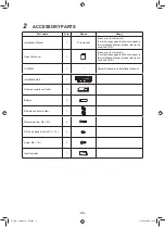
Page 96: ...to customers For other languages that do not appear in this installation Manual please refer to the enclosed CD R CD ROM 1 Owner s Manual and Installation Manual Installation plate 1 Wireless remote controller 1 Battery 2 Remote controller holder 1 Mounting screw Ø4 25R 6 Flat head wood screw Ø3 1 16R 2 Screw Ø4 10R 3 Heat insulator 1 BOOK_1130550101_EN indd 11 BOOK_1130550101_EN indd 11 11 2 2564...

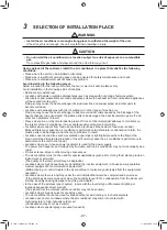
Page 97: ...ood oils are used Blocked filters may cause the air conditioner s performance to deteriorate condensation to form the plastic parts to be damaged and other such problems to result Locations near obstructions such as ventilation openings or lighting fixtures where the flow of the blown air will be disrupted a disruption of the air flow may cause the air conditioner s performance to deteriorate or t...

Page 98: ...ng hole sloped slightly Refrigerant piping must be protected from physical damage Install a plastic cover or equivalent Before installing the wireless remote controller 1 Remove the battery cover 2 Insert 2 new batteries R03 AAA type following the and positions Wireless remote controller Cover Batteries Hook Installation space The indoor unit shall be installed at least 2 5 m height Also it must b...

Page 99: ...in a place exposed to direct sunlight or close to a heating source such as a stove Keep the remote controller at least 1 m apart from the nearest TV set or stereo equipment This is necessary to prevent image disturb bounces or noise interference The location of the remote controller should be determined as shown below Indoor unit Side view Top view Indoor unit Reception range Remote controller Rec...

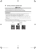
Page 100: ...ible If carrying in the indoor unit unpacked by necessity be sure to use buffering cloth etc to not damage the unit To move the indoor unit do not apply force to the refrigerant pipe drain pan foamed parts or resin parts etc Carry the package by two or more persons and do not bundle it with plastic band at positions other than specified Be careful to the following items when installating the unit ...

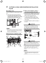
Page 101: ... the upper and lower parts to hook up the indoor unit 2 To mount the installation plate on a concrete wall with anchor bolts utilize the anchor bolt holes as illustrated in the above figure 3 Install the installation plate horizontally in the wall CAUTION When installing the installation plate with a mounting screw do not use the anchor bolt hole Otherwise the unit may fall down and result in pers...

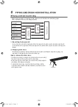
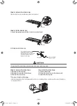
Page 102: ...e bottom left or right connection with a pair of nippers 2 Changing drain hose For leftward connection bottom leftward connection and rear leftward connection s piping it is necessary to change the drain hose and drain cap How to remove the drain hose The drain hose can be removed by removing the screw securing the drain hose and then pulling out the drain hose When removing the drain hose be care...

Page 103: ...rom the plug CAUTION Firmly insert the drain hose and drain cap otherwise water may leak How to remove the drain hose 1 Remove the front panel 2 Remove the screws of drain hose 3 Pull out the drain hose How to fix the drain hose 1 Put the drain hose 2 Screw the drain hose to the indoor unit 3 Install the front panel T In case of right or left piping After scribing slits of the front panel with a k...

Page 104: ...spring bender so as not to crush the pipe Bend the connecting pipe within a radius of 30 mm To connect the pipe after installation of the unit figure 545 mm Liquid side To the forefront of flare 645 mm Gas side Outward of indoor unit 43 mm R 30 mm Use polisin polyethylene core or the like for bending pipe Use the handle of screwdriver etc 80 NOTE If the pipe is bent incorrectly the indoor unit may...

Page 105: ...ION Bind the auxiliary pipes two and power supply wiring and control wiring with facing tape tightly In case of leftward piping and rear leftward piping bind the auxiliary pipes two only with facing tape Indoor unit Power supply wiring Control wiring Auxiliary pipes Installation plate Carefully arrange pipes so that any pipe does not stick out of the rear plate of the indoor unit Carefully connect...

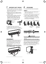
Page 106: ... the left side the unit must be screwed to the installation plate Lid screws Screws 1 Run the drain hose sloped downwards NOTE Hole should be made at a slight downward slant on the outdoor side 2 Put water in the drain pan and make sure that the water is drained out of doors 3 When connecting extension drain hose insulate the connecting part of extension drain hose with shield pipe 50 mm or more D...

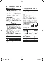
Page 107: ...PUMP 4 Check the gas leakage Connected points Pipe size dia mm MMK PIPE SIZE mm Gas side Liquid side UP027 to UP036 type 15 9 9 5 Permissible Piping Length and Height Difference They vary according to the outdoor unit For details refer to the Installation Manual attached to the outdoor unit Flaring ෬ Cut the pipe with a pipe cutter Remove burrs completely Remaining burrs may cause gas leakage ෬ In...

Page 108: ...oor unit CAUTION Do not scratch the inner surface of the flared part when removing burrs Flare processing under the condition of scratches on the inner surface of flare processing part will cause refrigerant gas leak Check that the flared part is not scratched deformed stepped or flattened and that there are no chips adhered or other problems after flare processing Do not apply refrigerating machi...

Page 109: ...ditioners are closely installed Wireless remote controller B setup 1 Push RESET button on the indoor unit to turn the air conditioner ON 2 Point the wireless remote controller at the indoor unit 3 Push and hold button on the wireless remote controller by the tip of the pencil 00 will be shown on the display 4 Push during pushing B will be shown on the display and 00 will be disappear and the air c...

Page 110: ... Use the cord clamps attached to the product Do not damage or scratch the conductive core and inner insulator of power and control wires when peeling them Use the power supply wire and control wires of specified thickness type and protective devices required Do not connect 208 240V power to the terminal blocks Uv U1 Uv U2 A B for control wiring Otherwise the system will fail Perform the electric w...

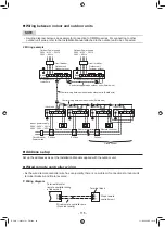
Page 111: ...ng Below 50 m 2 5 mm2 Control wiring Central controller wiring Use a 2 core non polarity wire To prevent any possible noise issues use a shielded 2 core wire The total stated length of communication wiring is determined by the interconnecting length of indoor to outdoor wire plus the length of the central control communication wire T Communication line TU2C Link models U series can be combined wit...

Page 112: ...line and Uc line are independent from another refrigerant line Total length of Uv and Uc lines L3 L4 in each refrigerant line is up to 1000 m U3 U4 Uh U1 U2 Uv A B U1 U2 Uv A B U1 U2 Uv A B U1 U2 Uv A B U2 Uv U5 U6 Uc U3 U4 Uh U1 U2 Uv U5 U6 Uc U3 U4 Uh U1 U2 Uv U5 U6 Uc U3 U4 Uh U1 Central control device Remote controller Outdoor unit Indoor unit U series Uh line L1 Up to 2000 m Uv and Uc line L2...

Page 113: ...n line L1 L2 L3 means the total length of the inter unit wire length between indoor and outdoor units added with the central control system wire length Central control device Remote controller Outdoor unit Indoor unit U series U series U3 U4 U1 U2 A B U1 U2 A B U1 U2 A B U1 U2 A B U2 U5 U6 U3 U4 U1 U2 U5 U6 U3 U4 U1 U2 U5 U6 U3 U4 U1 Uv Uv Uv Uv Other than U series Communication line L1 L2 L3 Up t...

Page 114: ... the wiring specifications and maximum number of connectable indoor units will be changed Pay attentions to their communication specifications when carrying out the installation maintenance or repair For its details refer to the Communication line in 10 Electrical connection BOOK_1130550101_EN indd 29 BOOK_1130550101_EN indd 29 11 2 2564 BE 19 18 11 2 2564 BE 19 18 Indoor unit Indoor unit Indoor u...

Page 115: ...oor units Shield wire Control wiring between indoor and outdoor units Shield wire Control wiring between indoor units Shield wire Indoor power supply 220V 240V 50 Hz 208V 230V 60 Hz Circuit breaker Power switch Pull box Pull box Group control Remote controller Remote controller Remote controller Pull box Address setup Set up the addresses as per the Installation Manual supplied with the outdoor un...

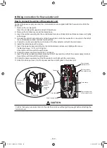
Page 116: ...Secure the earth line with the earth screw 9 Clamp the power supply wire with the cord clamp 10 Attach the terminal cover and the air inlet grille to the indoor unit CAUTION Be sure to refer to the wiring diagram attached inside the front panel Check local electrical cords an also any specific wiring instructions and limitations Do not catch the control wire when installing the clamp base Uv U1 Uv...

Page 117: ...o the terminal block and secure it tightly with screws Tightening torque 1 2 N m 0 12 kgf m Secure the earth line with the earth screw 8 Clamp the power supply wire with the cord clamp 9 Insert the power supply wire fasten terminal of the flow selector unit into the power supply terminal Secure the earth line with the earth screw 10 Clamp the power supply wire of the flow selector unit tight with ...

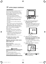
Page 118: ...all a wired remote controller separately as well Applicable controls setup settings at the site Remote controller model name RBC ASCU11 E Basic procedure Be sure to stop the air conditioner before making settings Change the setup while the air conditioner is not working CAUTION Set only the Code No shown in the following table Do NOT set any other Code No If a Code No not listed is set it may not ...

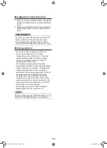
Page 119: ...CODE No in Procedure 4 specify 01 For the SET DATA in Procedure 5 select the SET DATA of filter sign lighting time from the following table SET DATA Filter sign lighting time 0000 None 0001 150H Factory setting 0002 2500H 0003 5000H 0004 10000H To secure better effect of heating When it is difficult to obtain satisfactory heating due to installation place of the indoor unit or structure of the roo...

Page 120: ...rol The wireless remote controller is unavailable for this control For cabling procedure and cables of the individual line Identical refrigerant line system refer to Electrical connection in this Manual Cabling between indoor units in a group is performed in the following procedure Connect the indoor units by connecting the remote controller inter unit cables from the remote controller terminal bl...

Page 121: ...t run is completed Operate the unit with the remote controller as usual For the procedure of the operation refer to the Owner s Manual attached to the outdoor unit A forced test run can be executed in the following procedure even if the operation stops by thermostat OFF In order to prevent a serial operation the forced test run is released after 60 minutes have passed and returns to the usual oper...

Page 122: ... short time because it applies excessive strength to the air conditioner A test operation of forced heating is unavailable Perform a test operation by heating operation using the switches of the remote controller However heating operation may be not carried out according to the temperature conditions Check wiring piping of indoor and outdoor units 1 When pushing RESET button for 10 seconds or more...

Page 123: ...and the indicators appear as an image indicating the troubleshooting history mode has been entered If Service check is displayed the mode enters in the troubleshooting history mode 01 Order of troubleshooting history appears in the temperature indicator The OFF timer indicator alternately shows the check code and the indoor Unit No in which the problem occurred 2 Each time the setting button is pu...

Page 124: ...ash E01 Communication trouble between indoor unit and remote controller Detected at remote controller side Remote controller E02 Remote controller transmission trouble Remote controller E03 Communication trouble between indoor unit and remote controller Detected at indoor unit side Indoor unit E04 Communication circuit trouble between indoor outdoor unit Detected at indoor unit side Indoor unit E0...

Page 125: ... sensor trouble I F F07 F07 01 TL1 sensor 02 TL2 sensor 03 TL3 sensor ALT TL1 TL2 or TL3 sensor trouble I F F08 F08 ALT TO sensor trouble I F F09 F09 01 TG1 sensor 02 TG2 sensor 03 TG3 sensor ALT TG1 TG2 or TG3 sensor trouble I F F10 ALT Indoor unit TA sensor trouble Indoor unit F11 ALT TF sensor trouble Indoor unit F12 F12 01 TS1 sensor 03 TS3 sensor ALT TS1 or TS3 sensor trouble I F F13 F13 01 C...

Page 126: ...t other than indoor unit with priority I F L07 SIM Group line in individual indoor unit Indoor unit L08 L08 SIM Indoor unit group Address unset Indoor unit I F L09 SIM Indoor unit capacity unset Indoor unit L10 L10 SIM Outdoor unit capacity unset I F L17 L17 SIM Outdoor unit type mismatch trouble I F L18 L18 SIM Flow selector unit trouble I F L20 SIM Duplicated central control addresses Indoor uni...

Page 127: ...mperature trouble No TH sensor 4 Motor current trouble D Sensor short circuit release trouble No TH sensor 5 Synchronization step out trouble Put in Fan Inverter No in mark ALT Outdoor unit fan inverter trouble Inverter P26 P26 01 Comp 1 side 02 Comp 2 side 03 Comp 3 side ALT IPM short protection trouble Inverter P29 P29 01 Comp 1 side 02 Comp 2 side 03 Comp 3 side ALT Comp position detective circ...

Page 128: ... Check code name Judging device Central control device indication Outdoor unit 7 segment display Sensor block display of receiving unit Auxiliary code Operation Timer Ready Flash C05 Sending trouble in central control device Communication Link C06 Receiving trouble in central control device Communication Link C12 Batch alarm of general purpose equipment control interface General purpose equipment ...

Page 129: ...ch is used in multi air conditioners is 0 3 kg m3 4 NOTE 1 If there are 2 or more refrigerating systems in a single refrigerating device the amounts of refrigerant should be as charged in each independent device e g charged amount 10 kg Outdoor unit e g charged amount 15 kg Indoor unit Room A Room B Room C Room D Room E Room F For the amount of charge in this example The possible amount of leaked ...

Page 130: ...01 0003 Have you changed lighting time of filter sign If not fill check mark x in NO CHANGE and fill check mark x in ITEM if changed respectively For check method refer to Applicable controls in this sheet Filter sign lighting time CODE No 01 Filter sign lighting time CODE No 01 Filter sign lighting time CODE No 01 Filter sign lighting time CODE No 01 NO CHANGE NONE 150H 2500H 5000H 10000H 0000 00...

Page 131: ...ted a fire and or electric shocks may occur Before proceeding with the test run install the front panel and cabinet Ensure that the following steps are taken when doing repairs on the refrigerating cycle 1 Do not allow any naked flames in the surrounding area If a gas stove or other appliance is being used extinguish the flames before proceeding If the flames are not extinguished they may ignite a...

Page 132: ...d securely remove screws 4 pcs at the front panel 3 2 Step 2 Lower screw cap How to open screw cap Step 1 Push up screw cap Screw cap Hooks Clue 4 Pull the clue of a front panel and remove the hook of the back body 5 Slightly open the lower part of the front panel then pull the upper part of the front panel toward you to remove it as shown on figure 132 ...

Page 133: ...vaporator 6 Remove TA sensor from the evaporator 7 Remove the 2 fixing screws that secures the electric parts box assembly unit display assembly and remove the electric parts box assembly Earth screw Earth line Washer TC sensor or TCJ sensor Sensor holder U3 U4 A B 1 2 3 TA sensor Earth line TCJ sensor exists a tube TC sensor no tube Fan motor connector Louver motor connector The sensor earth line...

Page 134: ...2 The drain hose can be removed by removing the screw securing the drain hose and then pulling out the drain hose 3 When removing the drain hose be careful of any sharp edges of steel plate The edges may cause injury To re installation To install the drain hose insert the drain hose firmly until the connection part contacts with heat insulator and then secure it with original screw Screw Drain hos...

Page 135: ... middle connector of louver motor code 5P 5 Remove 2 fixing screws from the drain pan then remove the drain pan assembly from the body back Screw Middle connector Unit display Screws To re installation Press the drain pan into the back body Please confirm that drain pan is attached certainly Please confirm that center arm of drain pan has fitted into back body certainly Center arm of drain pan Fit...

Page 136: ...re item 3 7 and 8 Loosen the set screw of the cross flow fan Hexagon screw driver Cross flow fan Vertical louver set 3 4 Remove 2 fixing screws of the motor band Pull the motor band and the fan motor outward Keep connector position and arrange fan motor wires follow figure To re installation Screws Fan motor Motor band Motor band Fan motor connector must not contact the Motor band Fan motor connec...

Page 137: ... motor and then pull out the lower side of heat exchanger follow the figure 10 Cross flow fan 3 4 5 Heat exchanger Cross flow fan Screw Bearing base Screw Heat exchanger Cross flow fan 1 To re installation Holding the set screw install the cross flow fan so that thin area on shaft of the fan motor comes to the mounting hole of the set screw To incorporate the fan motor and the motor into the posit...

Page 138: ...side of the main unit Remove 3 fixing screw at the upper right side of the heat exchanger Remove fixing screw at the under right side of the heat exchanger Follow the procedure item and Remove 4 fixing screws at the left side of the heat exchanger Heat exchanger Screw Heat exchanger Pipe holder Screw 2 1 138 ...

Page 139: ...No Part name Common procedure Procedure Remarks Microcomputer 1 Replace terminal block microcomputer ass y and the P C board ass y Perform procedure item and of Indoor Unit 139 ...

Page 140: ...ranged from to The CODE No DN may skip Replacement procedures Case 1 Before replacement the indoor unit can be turned on and the setting data can be read out by wired remote control operation EEPROM data read out 1 Refer to page 1 Writing the read out EEPROM data 3 Refer to page 2 Case 2 The EEPROM before replacement is defective and the setting data cannot be read out based on the customer inform...

Page 141: ...it only can be turned on 3 B In case that power of the indoor units cannot be turned on individually Case 1 a Remove temporarily the group wire connected to the terminal blocks A and B of the exchanged indoor units and proceed to b After connecting the remote controller wire only to the removed terminal block turn on power of the 3 3 indoor unit C In case that power of the indoor units cannot be t...

Page 142: ... to the EEPROM such as address setting etc Perform the steps 1 and 2 above again Change the CODE No DN to by pressing buttons for the temperature setting this is the setting for the filter sign lighting time The CODE No DN are ranged from to The CODE No DN is not limited to be serial No Even 1 If the setting data is different modify the setting data by pressing buttons for the timer setting to the...

Page 143: ...peration save function D0 0000 Unavailable 0001 Enable 0000 Available Presence of Application control kit TCB PCUC2E Communication protocol FC 0000 None 0000 TCC LINK 1Fb Remote controller operation 0000 Operation possible Indoor Unit terminating resistance 1FC 0000 OFF 0000 Default setting External static pressure F6 Heating suction temperature shift 06 0001 No automatic Automatic mode 0D Sensor ...

Page 144: ...SY VERTICAL LOUVER ASSY MOTOR LOUVER DRAIN PAN ASSY GEAR ASSY HORIZONTAL LOUVER FRONT HORIZONTAL LOUVER BACK DRAIN HOSE ASSY DRAIN CAP FAN MOTOR CROSS FLOW FAN ASSY BASE BEARING ASSY BEARING ASSY MOLD MOTOR COVER ASSY MOTOR BAND BACK MOTOR BAND FRONT REFRIGERATION CYCLE ASSY HOLDER SENSOR 244 43T46518 PIPE SHIELD SEAL FRONT SEAL UP HOLDER PIPE PIPE FIXTURE PLATE INSTALLATION ASSY TERMINAL COVER AS...

Page 145: ...No 401 43TN9351 405 43T50304 402 43T60448 406 43T50317 403 43T60078 407 43T6V932 404 43T50391 PC BOARD ASSY TERMINAL TERMIMAL BLOCK SENSOR THERMOSTAT 408 43T63356 SENSOR HEAT EXCHANGER SENSOR HEAT EXCHANGER PC BOARD ASSY HOLDER TA Description Description 145 ...

Page 146: ... in multi air conditioners is 0 3 kg m3 NOTE 1 If there are 2 or more refrigerating systems in a single refrigerating device the amounts of refrigerant should be as charged in each independent device For the amount of charge in this example The possible amount of leaked refrigerant gas in rooms A B and C is 10 kg The possible amount of leaked refrigerant gas in rooms D E and F is 15 kg NOTE 2 The ...

Page 147: ...144 9 MOO 5 BANGKADI INDUSTRIAL PARK TIVANON ROAD TAMBOL BANGKADI AMPHUR MUANG PATHUMTHANI 12000 THAILAND ...

Reviews: