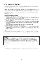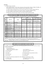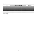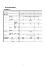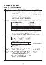
P1
Q1
(˚C)
a
K
J
I
P2
Q2
(˚C)
L
N
M
No
.
6
7
Item
Prevention of
cold air
discharge
Freeze preven-
tion control
(Low temp.
release)
Outline of specifications
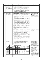
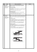
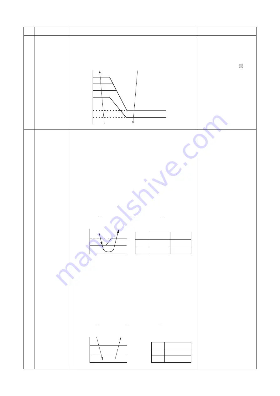
(1) In heating operation, the upper limit of the fan tap is set by
one with higher temperature of TC2 sensor and TCJ sensor.
• When B zone has continued for 6 minutes, the operation
shifts to C zone.
• In defrost time, the control point is set to +6°C.
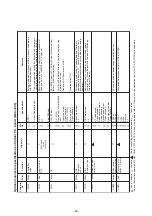
(1) In cooling operation, the air conditioner operates as de-
scribed below based upon temp. detected by TC1, TC2 and
TCJ sensors.
To prevent the heat exchanger from freezing, the operation
stops.
• When “J” zone is detected for 5 minutes, the forced
thermo is OFF.
• In “K” zone, the timer count is interrupted, and held.
• When “
IIIII
” zone is detected, the timer is cleared and the
operation returns to the normal operation.
• When the forced thermo-OFF became S0 with continua-
tion of “J” zone, operation of the the indoor fan in LOW (L)
mode until it reaches the “
IIIII
” zone.
It is reset when the following conditions are satisfied.
Reset conditions
1) TC1 > 12°C and TC2 > 12°C and TCJ > 12°C
2) 20 minutes passed after stop.
(2) In cooling operation, the air conditioner operates as
described below based upon temp. detected by TC2 and
TCJ sensors.
• When “M” zone is detected for 45 minutes, the forced
thermo is OFF.
• In “N” zone, the timer count is interrupted and held.
• When shifting to “M” zone again, the timer count restarts
and continues.
• If “L” zone is detected, the timer is cleared and the
operation returns to normal operation.
Reset conditions
1) TC1 > 12°C and TC2 > 12°C and TCJ > 12°C
2) 20 minutes passed after stop.
Remarks
• In D and E zones, priority
is given to remote control-
ler air speed setup.
• In A and B zones, “ ” is
displayed.
E
B
A
A zone: OFF
B zone:
Over 30˚C, below 32˚C, UL
C zone:
Over 32˚C, below 24˚C, L
D zone:
Over 24˚C, below 36˚C, H
E zone: HH
D
C
36
34
32
30
24
20
(˚C)
P1
Q1
TC1
TC2, TCJ
10°C (5°C)
10°C
0°C
–14°C
P2
Q2
TC2, TCJ
5°C
–2.0°C
- 20 -
Summary of Contents for MMK- UP0301HP Series
Page 16: ...3 WIRING DIAGRAM 16 ...


