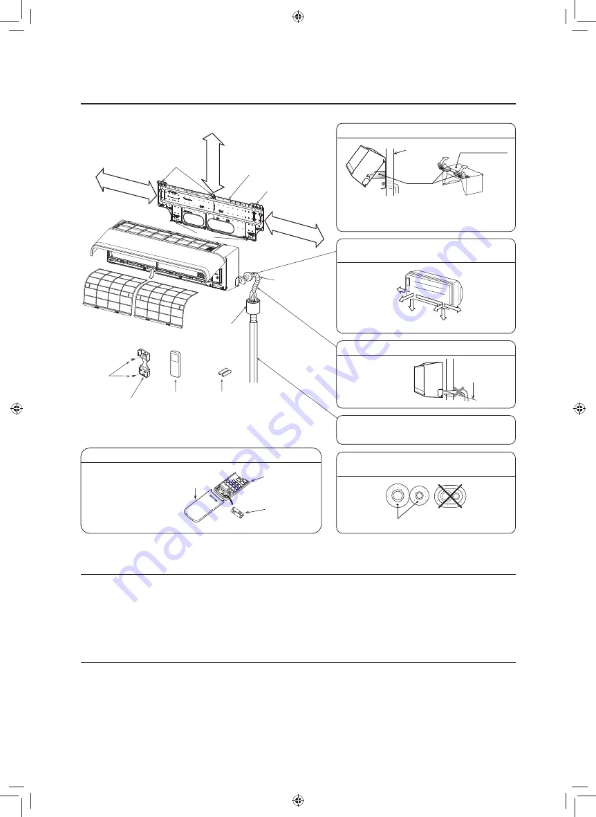
50 mm or more
Shield pipe
Hook
Installation plate
Air
fi
lter
(Attach to the front panel)
Hook
*1
*2
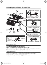
Installation diagram of Indoor and outdoor units
The auxiliary piping can be connected to the left,
rear left, rear right, right, bottom right or bottom left.
Right
Rear right
Bottom
right
Rear
left
Bottom left
Left
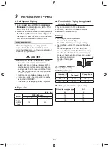
Insulate the refrigerant pipes separately
with insulation, not together.
6 mm thick heat resisting polyethylene foam
Batteries
Wireless
remote
controller
Remote control
holder
Flat head
wood
screw
Heat insulator
191 mm or more
170 mm or more
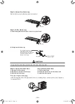
Split out 2 pieces of SPACER from indoor unit
packing material, insert between the indoor unit and
wall to tilt the indoor unit for better operation.
For the rear left, bottom left and left piping
Wall
SPACER
Split
Packing material
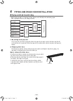
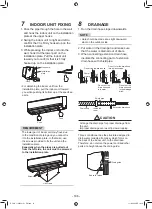
Do not allow the drain hose to get slack.
Make sure to run
the drain hose
sloped downward.
Cut the piping
hole sloped
slightly.
Refrigerant piping must be protected from physical
damage. Install a plastic cover or equivalent.
Before installing the wireless remote controller
1. Remove the battery
cover.
2. Insert 2 new batteries
(R03 [AAA] type)
following the (+) and (
−
)
positions.
Wireless
remote controller
Cover
Batteries
Hook
Installation space
The indoor unit shall be installed at least 2.5 m height.
Also it must be avoided to put anything on top of the indoor unit.
*1 Reserve space required to install the indoor unit and for service work.
Keep 50 mm or more for clearance between top plate of the indoor unit and the ceiling surface.
*2 Provide a space as shown for service clearance for the cross
fl
ow fan.
Installation place
• A place which provides the spaces around the indoor unit as shown in the above diagram.
• A place where there is no obstacle near the air inlet and outlet.
• A place that allows easy installation of the piping to the outdoor unit.
• A place which allows the front panel to be opened.
BOOK_1130550101_EN.indd 13
BOOK_1130550101_EN.indd 13
11/2/2564 BE 19:18
11/2/2564 BE 19:18
- 98 -
Summary of Contents for MMK- UP0301HP Series
Page 16: ...3 WIRING DIAGRAM 16 ...


