background image

– 26 –

26-EN

Installation Manual

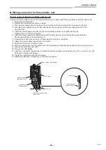
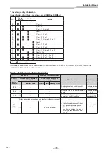
5

Push the menu button to make Set data 
[

fl

ash. Change Set data [

] with 

[ ] [ ] setting button.

6

Push OFF timer button.
By doing so, the setup is completed.

•  To change other settings of the selected indoor 

unit, repeat from Procedure


4

.

7

When all the settings have been completed, 
push ON/OFF button to determine the settings.

” 

fl

ashes and then the display content 

disappears and the air conditioner enters the normal 
stop mode. (The remote controller is unavailable 
while “

” is 

fl

ashing.)

•  To change settings of another indoor unit, repeat 

from Procedure


1

.


„

 Change of lighting time of 

fi

lter sign

According to the installation condition, the lighting time 
of the 

fi

 lter sign (Noti

fi

 cation of 

fi

 lter cleaning) can be 

changed.
Follow to the basic operation procedure
(

1


2


3


4


5


6

).

• For the CODE No. in Procedure 

4

, specify [01].

• For the [SET DATA] in Procedure 

5

, select the 

SET DATA of 

fi

lter sign lighting time from the following 

table.

SET DATA

Filter sign lighting time

0000

None

0001

150H (Factory setting)

0002

2500H

0003

5000H

0004

10000H


„

 To secure better effect of heating

When it is dif

fi

cult to obtain satisfactory heating due 

to installation place of the indoor unit or structure of 
the room, the detection temperature of heating can be 
raised. Also use a circulator, etc. to circulate heat air near 
the ceiling.
Follow to the basic operation procedure
(

1


2


3


4


5


6

).

• For the CODE No. in Procedure 

4

, specify [06].

• For the SET DATA in Procedure 

5

, select the 

SET DATA of shift value of detection temperature to be 
set up from the table below.

SET DATA

Detection temp shift value

0000

 No shift

0001

+1°C

0002

+2°C

0003

+3°C (Factory setting)

0004

+4°C

0005

+5°C

0006

+6°C


„

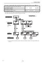
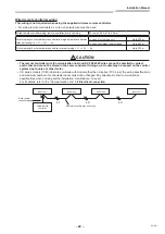
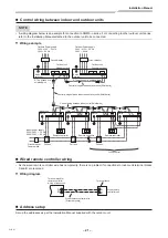
 Group  control

•  The wired remote controller only can control a group 

control. The wireless remote controller is unavailable 
for this control.

•  For cabling procedure and cables of the individual line 

(Identical refrigerant line) system, refer to “Electrical 
connection” in this Manual.

•  Cabling between indoor units in a group is performed 

in the following procedure.
Connect the indoor units by connecting the remote 
controller inter-unit cables from the remote controller 
terminal blocks (A, B) of the indoor unit connected with 
a remote controller to the remote controller terminal 
blocks (A, B) of the other indoor unit.
(Non-polarity)

•  For address setup, refer to the Installation Manual 

attached to the outdoor unit.

NOTE

Net work adapter (Model RBC-U32PGP) can not connect 
to this air conditioner.

Summary of Contents for MML-UP0071NHP-E

Page 1: ...Installation Manual Indoor Unit Model name Console Type For commercial use MML UP0071NHP E MML UP0091NHP E MML UP0121NHP E MML UP0151NHP E MML UP0181NHP E SUPER MODULAR MULTI SYSTEM AIR CONDITIONER ...

Page 2: ...yer Information If U series models TU2C Link are combined with models other than U series TCC Link the wiring specifications and maximum number of connectable indoor units will be changed Pay attentions to their communication specifications when carrying out the installation maintenance or repair For its details refer to the Electrical connection in this Manual 1 PRECAUTIONS FOR SAFETY 4 2 ACCESSO...

Page 3: ...on relocation and removal has the qualifications pertaining to this refrigerant handling and piping work as stipulated by the local laws and regulations and he or she is a person who has been trained in matters relating to refrigerant handling and piping work on the air conditioners made by Toshiba Carrier Corporation or alternatively he or she has been instructed in such matters by an individual ...

Page 4: ... that failure to adhere to the directions in the warning could result in serious bodily harm 1 or loss of life if the product is handled improperly CAUTION Text set off in this manner indicates that failure to adhere to the directions in the caution could result in slight injury 2 or damage 3 to property if the product is handled improperly 1 Serious bodily harm indicates loss of eyesight injury b...

Page 5: ...erson 1 is allowed to remove the front panel of the indoor unit or service panel of the outdoor unit and do the work required Before carrying out the installation maintenance repair or removal work be sure to set the circuit breaker to the OFF position Otherwise electric shocks may result Place a Work in progress sign near the circuit breaker while the installation maintenance repair or removal wo...

Page 6: ...nut may cause a crack in the flare nut after a long period which may result in refrigerant leakage After the installation or servicing work confirm that refrigerant gas does not leak If refrigerant gas leaks into the room and flows near a fire source such as a cooking range noxious gas may be generated When the air conditioner has been installed or relocated follow the instructions in the Installa...

Page 7: ...onditioner after having completed the work check that the front panel of the indoor unit and service panel of the outdoor unit are closed and set the circuit breaker to the ON position You may receive an electric shock if the power is turned on without first conducting these checks When you have noticed that some kind of trouble such as when an error display has appeared there is a smell of burnin...

Page 8: ...pressure is approx 1 6 times higher than that of refrigerant R22 Accompanied with the new refrigerant refrigerating oil has also been changed Therefore during installation work be sure that water dust former refrigerant or refrigerating oil does not enter the refrigerating cycle To prevent charging an incorrect refrigerant and refrigerating oil the sizes of connecting sections of charging port of ...

Page 9: ...al 1 Owner s Manual 1 CD ROM 1 Installation plate 1 Wireless remote controller 1 Battery 2 Remote control holder 1 Mounting screw Ø4 x 25r 8 Flat head wood screw Ø3 1 x 16r 2 Heat insulator 1 Banding band for anchoring the insulated pipes 2 Banding band for banding control and remote controller wire 1 ...

Page 10: ...nce generate mist or dew drop or deform or damage resin parts Place where organic solvent is used nearby Place close to a machine generating high frequency Place where the discharged air blows directly into the window of the neighbour house Outdoor unit Place where noise of the outdoor unit is easily transmitted When install the outdoor unit on the boundary with the neighbour pay due attention to ...

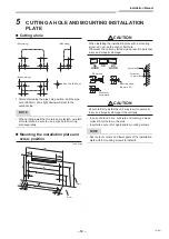
Page 11: ...ight Bottom Rear Rear left left Bottom left right right In case of right or left piping Cut dot line area Insulate the refrigerant pipes separately with insulation not together 8 mm thick heat resisting polyethylene foam Installation place A place which provides the spaces around the indoor unit as shown in the diagram A place where there are no obstacles near the air inlet and outlet A place whic...

Page 12: ...nstallation work to guard against strong wind or earthquake An incomplete installation can cause accidents by the units falling and dropping REQUIREMENT Strictly comply with the following rules to prevent damage of the indoor units and human injury Do not put a heavy article on the indoor unit Even units are packaged Carry in the indoor unit as it is packaged if possible If carrying in the indoor ...

Page 13: ...00 2 0 5 15 15 9 0 15 15 272 560 590 670 Floor Wall CAUTION When installing the installation plate with a mounting screw do not use the anchor bolt hole Otherwise the unit may fall down and result in personal injury and property damage OK NO GOOD NO GOOD Ø5 mm hole Clip anchor local parts Mounting screw Ø4 mm x 25r Anchor bolt Projection 15 mm or less CAUTION Failure to firmly install the unit may...

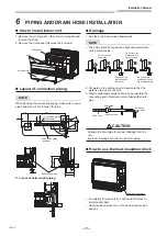
Page 14: ...loped downwards NOTE The hole should be made at a slight downward slant on the outdoor side Do not rise the drain hose Do not form the drain hose into a wavy shape Do not put the drain hose end into water Do not put the drain hose end in the drainage ditch 2 Put water in the drain pan and make sure that the water is drained out of doors 3 When connecting extension drain hose insulate the connectin...

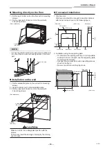
Page 15: ...allation 4 screw M4 x 25L 1000 mm or less CAUTION Make sure to fix it at a designated position with the screws Failure may result the damage of piping by the turning over of a set Concealed installation 1 Wall hole size Wall hole size should be enough to keep the distance with indoor unit as shown in the following figure 300 or more Front view Unit mm Side view 300 or more Indoor unit 300 or more ...

Page 16: ...are recommended However the conventional tools can be used by adjusting projection margin of the copper pipe 4 Projection margin in flaring B Unit mm RIDGID Clutch type Outer dia of copper pipe R410A tool used Conventional tool used R410A R410A 6 4 9 5 0 to 0 5 1 0 to 1 5 12 7 4 Flaring dia meter size A Unit mm Outer dia of copper pipe A 0 0 4 R410A 6 4 9 1 9 5 13 2 12 7 16 6 In case of flaring fo...

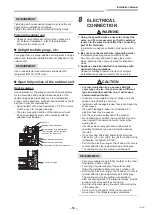
Page 17: ...plete grounding cause an electric shock Do not connect ground wires to gas pipes water pipes lightning rods or ground wires for telephone wires 3 Appliance shall be installed in accordance with national wiring regulations Capacity shortage of power circuit or incomplete installation may cause an electric shock or a fire CAUTION For communication line use wires with the same type and size If each w...

Page 18: ...ted total current values of the indoor units Power supply wiring Below 50 m 2 5 mm2 Control wiring Central controller wiring Use a 2 core non polarity wire To prevent any possible noise issues use a shielded 2 core wire The total stated length of communication wiring is determined by the interconnecting length of indoor to outdoor wire plus the length of the central control communication wire T Co...

Page 19: ...tral control line Uc line Between outdoor and outdoor units Uv line and Uc line are independent from another refrigerant line Total length of Uv and Uc lines L3 L4 in each refrigerant line is up to 1000 m U3 U4 Uh U1 U2 Uv A B U1 U2 Uv A B U1 U2 Uv A B U1 U2 Uv A B U2 Uv U5 U6 Uc U3 U4 Uh U1 U2 Uv U5 U6 Uc U3 U4 Uh U1 U2 Uv U5 U6 Uc U3 U4 Uh U1 Central control device Remote controller Outdoor unit...

Page 20: ... size 1 25 to 2 0 mm Up to 100 m The length of the communication line L1 L2 L3 means the total length of the inter unit wire length between indoor and outdoor units added with the central control system wire length Central control device Remote controller Outdoor unit Indoor unit U series U series U3 U4 U1 U2 A B U1 U2 A B U1 U2 A B U1 U2 A B U2 U5 U6 U3 U4 U1 U2 U5 U6 U3 U4 U1 U2 U5 U6 U3 U4 U1 U...

Page 21: ...Ln Up to 200 m CAUTION The remote controller wire Communication line and AC 208 240V wires cannot be parallel to contact each other and cannot be stored in the same conduits If doing so a trouble may be caused on the control system due to noise or other factor If U series models TU2C Link are combined with models other than U series TCC Link the wiring specifications and maximum number of connecta...

Page 22: ...door Outdoor unit Follower outdoor Control wiring between outdoor units Shield wire Control wiring between indoor and outdoor units Shield wire Control wiring between indoor units Shield wire Indoor power supply 220V 240V 50 Hz 208V 230V 60 Hz Circuit breaker Power switch Pull box Pull box Group control Remote controller Remote controller Remote controller Pull box Wired remote controller wiring A...

Page 23: ...lock and secure it tightly with screws Tighten torque 1 2 N m 0 12 kgf m 6 Clamp the power supply wire with the cord clamp 7 Attach the terminal cover with a screw CAUTION Be sure to refer to the wiring diagram attached inside the front panel Check local electrical cords and also any specific wiring instructions and limitations Do not catch the control wire when installing the clamp base L N 50 10...

Page 24: ... band through the hole of the mount base 7 Band the control wire and the remote controller wire in the banding band 8 Attach the LED base terminal cover and front panel U1 A B U2 230 230 10 10 600 mm Uv U1 Uv U2 A B Stripping length of the control wire How to remove LED base Connecting control wire and remote controller Shield wire Control wire Slide right side to remove LED base Remote control wi...

Page 25: ...al of the flow selector unit into the power supply terminal Secure the earth line with the earth screw 7 Connect the control wire connector of flow selector unit to the control wire 8 Clamp the power supply wire with the cord clamp 9 Attach the terminal cover with a screw 10 Take the control wire out of the cable slot on the rear panel so that it produces about 600 mm from the front 11 Remove the ...

Page 26: ...remote controller and simple remote controller by itself so install a wired remote controller separately as well Applicable controls setup settings at the site Remote controller model name RBC ASC11E Basic procedure Be sure to stop the air conditioner before making settings Change the setup while the air conditioner is not working CAUTION Set only the Code No shown in the following table Do NOT se...

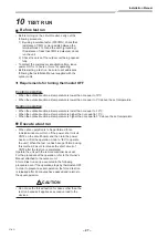
Page 27: ...eating due to installation place of the indoor unit or structure of the room the detection temperature of heating can be raised Also use a circulator etc to circulate heat air near the ceiling Follow to the basic operation procedure 1 2 3 4 5 6 For the CODE No in Procedure 4 specify 06 For the SET DATA in Procedure 5 select the SET DATA of shift value of detection temperature to be set up from the...

Page 28: ...thod be sure to release the short circuit of CN72 after the test run is completed Operate the unit with the remote controller as usual For the procedure of the operation refer to the Owner s Manual attached to the outdoor unit A forced test run can be executed in the following procedure even if the operation stops by thermostat OFF In order to prevent a serial operation the forced test run is rele...

Page 29: ... run is permitted 2 Push ON OFF button 3 Push menu button to select the operation mode Select Cool or Heat with setting button and then push menu button three times again to determine the operation mode Do not run the air conditioner in a mode other than Cool or Heat The temperature setting function does not work during test run The check code is displayed as usual 4 After the test run push OFF ti...

Page 30: ...ck wiring piping of indoor and outdoor units 1 When pushing button for 10 seconds or more Pi sound is heard and the operation changes to a forced cooling operation After approx 3 minutes a cooling operation starts forcedly Check cool air starts blowing If the operation does not start check wiring again 2 To stop a test operation push button once again Approx 1 second The louver closes and the oper...

Page 31: ...ds and the indicators appear as an image indicating the troubleshooting history mode has been entered If Service check is displayed the mode enters in the troubleshooting history mode 01 Order of troubleshooting history appears in the temperature indicator The OFF timer indicator alternately shows the check code and the indoor Unit No in which the problem occurred 2 Each time the setting button is...

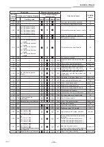
Page 32: ...play of receiving unit Auxiliary code Operation Timer Ready Flash E01 Communication trouble between indoor unit and remote controller Detected at remote controller side Remote controller E02 Remote controller transmission trouble Remote controller E03 Communication trouble between indoor unit and remote controller Detected at indoor unit side Indoor unit E04 Communication circuit trouble between i...

Page 33: ...06 01 TE1 sensor 02 TE2 sensor 03 TE3 sensor ALT TE1 TE2 or TE3 sensor trouble I F F07 F07 01 TL1 sensor 02 TL2 sensor 03 TL3 sensor ALT TL1 TL2 or TL3 sensor trouble I F F08 F08 ALT TO sensor trouble I F F09 F09 01 TG1 sensor 02 TG2 sensor 03 TG3 sensor ALT TG1 TG2 or TG3 sensor trouble I F F10 ALT Indoor unit TA sensor trouble Indoor unit F11 ALT TF sensor trouble Indoor unit F12 F12 01 TS1 sens...

Page 34: ...rity SIM Duplicated indoor units with priority Displayed in unit other than indoor unit with priority I F L07 SIM Group line in individual indoor unit Indoor unit L08 L08 SIM Indoor unit group Address unset Indoor unit I F L09 SIM Indoor unit capacity unset Indoor unit L10 L10 SIM Outdoor unit capacity unset I F L17 L17 SIM Outdoor unit type mismatch trouble I F L18 L18 SIM Flow selector unit trou...

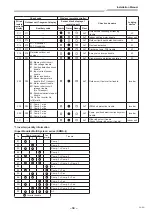
Page 35: ...2 Input current sensor trouble 3 Motor lock trouble C Sensor temperature trouble No TH sensor 4 Motor current trouble D Sensor short circuit release trouble No TH sensor 5 Synchronization step out trouble Put in Fan Inverter No in mark ALT Outdoor unit fan inverter trouble Inverter P26 P26 01 Comp 1 side 02 Comp 2 side 03 Comp 3 side ALT IPM short protection trouble Inverter P29 P29 01 Comp 1 side...

Page 36: ...by central control device Check code Wireless remote controller Check code name Judging device Central control device indication Outdoor unit 7 segment display Sensor block display of receiving unit Auxiliary code Operation Timer Ready Flash C05 Sending trouble in central control device Communication Link C06 Receiving trouble in central control device Communication Link C12 Batch alarm of general...

Page 37: ... installed room m3 Concentration limit kg m3 The concentration limit of R410A which is used in multi air conditioners is 0 44 kg m3 NOTE 1 If there are 2 or more refrigerating systems in a single refrigerating device the amounts of refrigerant should be as charged in each independent device Room A Room B Room C Room D Room E Room F e g charged amount 10 kg Outdoor unit e g charged amount 15 kg Ind...

Page 38: ...NGE STANDARD HIGH CEILING 1 HIGH CEILING 3 0000 0001 0003 Have you changed lighting time of filter sign If not fill check mark x in NO CHANGE and fill check mark x in ITEM if changed respectively For check method refer to Applicable controls in this sheet Filter sign lighting time CODE No 01 Filter sign lighting time CODE No 01 Filter sign lighting time CODE No 01 Filter sign lighting time CODE No...

Page 39: ...144 9 Moo 5 Bangkadi Industrial Park Tivanon Road Tambol Bangkadi Amphur Muang Pathumthani 12000 Thailand 1112750298 ...

Reviews: