– 31 –
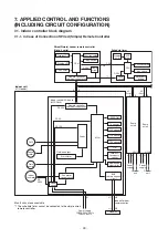
7-1-2. In Case of Connection of Wireless Remote Controller
A
B
L
U1U2
N
Same
as left
Same
as left
A
B
A
B
L
U1U2
N
Outdoor
unit
Outdoor
unit
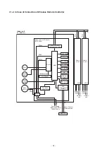
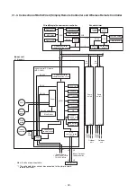
Indoor control P.C. board
(MCC-164
3
)
DC12V
DC5V
DC20V
Power
circuit
Outside output
Fan motor
control circuit
Start/Alarm
BUS
communication
circuit
MCU
EEPROM
TA sensor
TC1 sensor
TC2 sensor
TCJ sensor
HA
Wireless/
Occupancy
sensor
Application
control kit
Driver
Remote controller
communication circuit
DC
280V
Indoor unit
#1 (Header)
Indoor
fan motor
U1 U2
U1 U2
Power supply
1Ø220-240V, 50Hz
1Ø220V, 60Hz
Power
supply
Power
supply
Indoor/Outdoor
communication
Outdoor unit
#2
#
3
(Follower)
(Follower)
L N
PMV
Louver
motor
Drain
pump

