background image

– 33 –

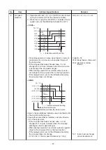
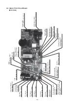
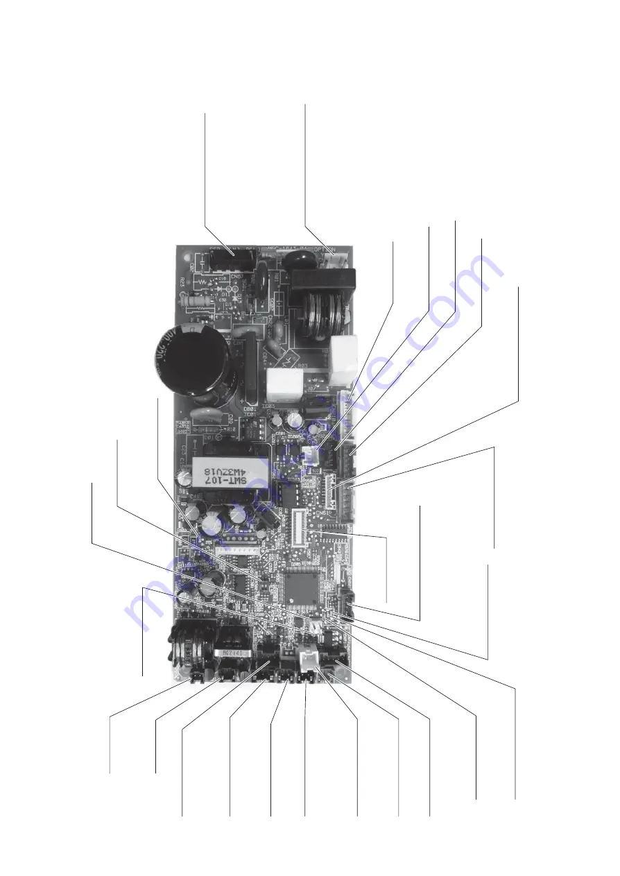
7-2. Indoor Print Circuit Board

(MCC-1643)

P

o

w

er supply

CN67 (Blac

k), A

C220-240V

Option po

w

e

r supply

CN

3

09 (Y

ello

w), A

C220-240V

P

o

w

er supply LED of

microprocessor

D501 (Red)

P

o

w

er supply LED

of remote controller

D40

3

 (Red)

Filter option SW

SW501

PMV output

CN82 (Blue), DC12V

Indoor/Outdoor centr

al

control comm

unication LED

D50

3

 (Y

ello

w)

Application control kit

CN521 (Red),  DC12V

, 5V

Output f

or FS unit

CN81 (Blac

k), DC12V

TC2 sensor

CN101 (Blac

k), DC5V

Dr

ain pump

CN504 (White), D12V

T

A

 sensor

CN104 (Y

ello

w), DC5V

Gr

ille up/do

wn

CN20 (Br

u

e)

CHK

CN71 (White), DC5V

DISP

CN72 (White), DC5V

TCJ sensor

CN102 (Red), DC5V

Float SW

CN

3

4 (Red),  DC12V

HA(T10)

CN61 (Y

ello

w), DC12V

Wireless remote control or

Occupancy sensor

CN214 (White)

DC f

an motor

CN210 (White)

V

e

ntilation output

CN

3

2 (White), D12V

TC1 sensor

CN100 (Bro

wn), DC5V


Indoor/Outdoor

comm

unication

CN40 (Blue)

Remote controller

CN41 (Blue), DC20V

Remote controller

comm

unication LED

D504 (Green)

Louv

e

r

CN510 (White)

Summary of Contents for MMU-AP0057MH-E

Page 1: ... 1 Jul 2017 SERVICE MANUAL AIR CONDITIONER MULTI TYPE INDOOR UNIT PRINTED IN JAPAN Jan 2017 ToMo Compact 4 way Cassette type MMU AP0057MH E TR MMU AP0077MH E TR MMU AP0097MH E TR MMU AP0127MH E TR MMU AP0157MH E TR MMU AP0187MH E TR ...

Page 2: ...ote Controller 32 7 2 Indoor Print Circuit Board 33 7 3 Optional connector specifications of indoor P C board 34 7 4 Test operation of indoor unit 35 7 5 Method to set indoor unit function DN code 38 7 6 Applied control of indoor unit 42 8 TROUBLESHOOTING 56 8 1 Overview 56 8 2 Troubleshooting method 57 8 3 Troubleshooting based on information displayed on remote controller 63 8 4 Check Codes Disp...

Page 3: ...he knowledge related to this work The qualified service person who is allowed to work at heights has been trained in matters relating to working at heights with the air conditioners made by Toshiba Carrier Corporation or alternatively he or she has been instructed in such matters by an individual or individuals who have been trained and is thus thoroughly acquainted with the knowledge related to t...

Page 4: ...xecuted Indicates possibilities assumed that a danger causing a death or serious injury of the repair engineers the third parties and the users due to troubles of the product after work when an incorrect work has been executed Indicates contents assumed that an injury or property damage may be caused on the repair engineers the third parties and the users due to troubles of the product after work ...

Page 5: ...connect all remote electric power supplies before servicing ELECTRICAL SHOCK HAZARD Disconnect all remote electric power supplies before servicing WARNING WARNING Moving parts Do not operate unit with grille removed Stop the unit before the servicing Moving parts Do not operate unit with grille removed Stop the unit before the servicing CAUTION CAUTION Do not touch the aluminium fins of the unit D...

Page 6: ...e proceeding with the work When you have noticed that some kind of trouble such as when a check code display has appeared there is a smell of burning abnormal sounds are heard the air conditioner fails to cool or heat or water is leaking has occurred in the air conditioner do not touch the air conditioner yourself but set the circuit breaker to the OFF position and contact a qualified service pers...

Page 7: ...e intake grille of the indoor unit to undertake work When working at heights use a ladder which complies with the ISO 14122 standard and follow the procedure in the ladder s instructions Also wear a helmet for use in industry as protective gear to undertake the work Before working at heights put a sign in place so that no one will approach the work location before proceeding with the work Parts an...

Page 8: ...ute of the service port is changed from one of the former R22 Do not use any refrigerant different from the one specified for complement or replacement Otherwise abnormally high pressure may be generated in the refrigeration cycle which may result in a failure or explosion of the product or an injury to your body For an air conditioner which uses R410A never use other refrigerant than R410A For an...

Page 9: ...airtight test The charge hose must be connected in such a way that it is not slack For the installation moving reinstallation work follow to the Installation Manual If an incorrect installation is done a trouble of the refrigerating cycle water leak electric shock or fire is caused Check after repair Once the repair work has been completed check for refrigerant leaks and check the insulation resis...

Page 10: ...t to another outdoor unit Capacity overflow may occur on the terminal block and may result in fire Do not install the air conditioner in a location that may be subject to a risk of expire to a combustible gas If a combustible gas leaks and becomes concentrated around the unit a fire may occur Install the indoor unit at least 2 5 m above the floor level since otherwise the users may injure themselv...

Page 11: ...77MH E MMU AP0077MH TR MMU AP0097MH E MMU AP0097MH TR MMU AP0127MH E MMU AP0127MH TR MMU AP0157MH E MMU AP0157MH TR MMU AP0187MH E MMU AP0187MH TR Commercial name Super Modular Multi System Air Conditioner Super Heat Recovery Multi System Air Conditioner MiNi Super Modular Multi System Air Conditioner MiNi SMMS series Complies with the provisions of the Machinery Directive Directive 2006 42 EC and...

Page 12: ...g Heating MMU AP0057MH E MMU AP0077MH E MMU AP0097MH E MMU AP0127MH E MMU AP0157MH E MMU AP0187MH E MMU AP0057MH TR MMU AP0077MH TR MMU AP0097MH TR MMU AP0127MH TR MMU AP0157MH TR MMU AP0187MH TR 15 2 5 15 2 5 15 2 5 15 2 5 15 2 5 15 2 5 15 2 5 15 2 5 15 2 5 15 2 5 15 2 5 15 2 5 ...

Page 13: ... 0 41 0 38 0 43 0 39 Appearance Main Unit Zinc hot dipping steel plate Heat insulating material attached to only upper plate Ceiling Panel Model Name RBC UM21PG W E 䋨 2䋩 Panel Color Gran White Mansell 5PB9 1 Outer Main Unit Height 䋨 3䋩 mm 256 dimension Width mm 575 Depth 䋨 4䋩 mm 575 Ceiling Panel Height 䋨 3䋩 mm 12 Width mm 620 Depth mm 620 Total weight Main Unit kg 15 Ceiling Panel kg 2 5 Heat exc...

Page 14: ...anel Height 䋨 3䋩 mm 12 Width mm 620 Depth mm 620 Total weight Main Unit kg 15 Ceiling Panel kg 2 5 Heat exchanger Finned tube Soundproof Heat insulating material Non flammable insulation Fan Turbo fan Fan unit Standard air flow M M L L m 3 h 594 550 504 420 402 660 600 552 480 468 840 740 642 540 522 Motor W 60 Air filter Standard filter Long life filter Controller 䋨 2䋩 Remote controller Connectin...

Page 15: ...ng An obstacle Indoor unit Stand up Bottom face of ceiling standing size Stand up 450 Check port Hanging bolt M10 or W3 8 Procured by locally 162 Bottom face of ceiling N 1000mm or more ote IF there is no ceiling board the length of the hanging bolt shall be more than 400mm Wiring entry for power supply Wiring entry for remote control Drain up Indoor unit Bottom face of ceiling 450 Check port For ...

Page 16: ...2 5 4 CN20 BLU 1 WHI CN32 GRL 5 3 1 2 4 CN521 RED reshuffling High ceilling CN71 DC15V DC 7V DC12V DC20V CN102 BLK CN101 ON 1 2 CHK SW501 RED INDICAT ION WHI WHITE BLK BLACK YEL YELLOW Connector Parts Name BLU BLUE RED RED COLOR TCJ TC2 t t 7 MS 4 1 2 3 CN210 WHI 3 6 5 7 6 2 1 3 4 5 FM 1 20 19 18 12 9 1011 8 141516 13 CN510 WHI 17 M CN104 1 1 2 WHI CN504 3 RED CN34 DM FS TA Option 1 2 BRW CN100 TC...

Page 17: ...motor Float switch Drain pump motor TA sensor TC1 sensor TC2 sensor TCJ sensor ICF 340D60 1 EFM MD12TF MSBPC20F04 FS 0218 102 MDP 1401 Lead wire length 818 mm Vinyl tube Ø4 size lead wire length 400 mm Vinyl tube Ø6 size lead wire length 500 mm Vinyl tube Black Ø6 size lead wire length 400 mm Vinyl tube Red EFM 25YGTF 2 EFM 40YGTF 3 ...

Page 18: ...ration 2 Controls under cool in heating operation 3 Recovers refrigerant oil in cooling operation 4 Recovers refrigerant oil in heating operation Temp Sensor Connector CN104 2P Yellow 1 Detects indoor suction temperature Functional outline 2 TC1 Connector CN100 3P Brown 1 Controls PMV super heat in cooling operation 3 TC2 4 TCJ Connector CN101 2P Black 1 Controls PMV under cool in heating operatio...

Page 19: ...r the operation mode is selected Remote controller command STOP FAN COOL DRY HEAT AUTO SHRM only Control outline Air conditioner stops Fan operation Cooling operation Dry operation Heating operation Ta and Ts automatically select COOL HEAT operation mode for operation The operation is performed as shown in the following figure according to Ta value at the first time only In the range of Ts 1 Ta Ts...

Page 20: ...ied out as shown below When 1 5 exceeds against Tsh 10 minutes and after thermo OFF heating operation Thermo OFF exchanges to cooling operation Description in the parentheses shows an example of cooling ON OFF When 1 5 lowers against Tsc 10 minutes and after thermo OFF cooling operation Thermo OFF exchanges to heating operation 2 For the automatic capacity control after judgment of cooling heating...

Page 21: ...e HEAT Value in the parentheses indicates one when thermostat of the remote controller works Value without parentheses indicates one when thermo stat of the body works If the air speed has been changed once it is not changed for 1 minute However when the air speed exchanged the air speed changes When heating operation has started select an upward slope for the air speed that is the high position I...

Page 22: ... has continued for 6 minutes the operation shifts to C zone In defrost time the control point is set to 6 C TCJ Temperature of indoor heat exchanger sensor In D and E zones priority is given to remote control ler air speed setup In A zone is displayed 7 Prevention of cold air discharge E B A A zone OFF B zone Over 26 C below 28 C ULTRA LOW LL C zone Over 28 C below 30 C LOW L D zone Over 30 C belo...

Page 23: ...ted for 45 minutes the thermostat is forcedly off In N zone the timer count is interrupted and held When shifting to M zone again the timer count restarts and continues If L zone is detected the timer is cleared and the operation returns to normal operation Reset conditions 1 TC1 12 C and TC2 12 C and TCJ 12 C 2 20 minutes passed after stop P1 Q1 C a K J P2 Q2 C L N M value When the power supply i...

Page 24: ...peration of the drain pump if the float switch operates the drain pump continuously operates and a check code is issued 3 During stop status of the drain pump if the float switch operates the thermostat is forcedly off and this control operates the drain pump After continuous operation of the float switch for approx 5 minutes this control stops the operation and a check code is issued 1 When the u...

Page 25: ...tem performs Recovery operation for heating refrigerant Oil HEAT READY Displayed on the remote controller The indoor fan stops in order to prevent discharge of cool air when heating operation started or during heating operation including the defrost operation during thermo OFF 1 Selection of the contents that can be operated by the remote controller at the indoor unit side is possible according to...

Page 26: ...vidually set or the locked louver closes fully when the unit stops and the louver is automatically set to horizontal discharge position when PRE HEAT Heating ready is displayed heating thermo is off Individual air direction setup Pushing UNIT LOUVER Louver select button enables every discharge port to set up the air direction The louver numbers that are displayed on the display part correspond to ...

Page 27: ...ypes of the swing modes can be also selected and set by the setup data of Item code DN F0 In case of selecting the Swing mode Dual swing or Cycle swing the following numerals is displayed at the center of the remote controller screen for approx 3 seconds when SWING FIX button was pushed to select SWING No display for the standard swing Remarks Carry out setting operation during stop of the unit ot...

Page 28: ...air direction setup Illustration on the remote controller screen 19 DC motor 1 When the fan stator positioning is performed for the starter and the rotor Vibrate slightly 2 DC motor operates according to the command from the indoor controller Note If the fan rotates by entry of outside air etc while the air conditioner stopped the indoor unit may operate as the fan motor stops Note If the fan lock...

Page 29: ...nd operates according to the operation at absent time if time or absence of the setting contents continues However time counting starts after the room temperature is stabilized after for 30 minutes operation 3 The operation at absent time can be changed by DN code B7 4 If the operation at absent time stops during group operation or absence is fixed in each system the operation starts circular oper...

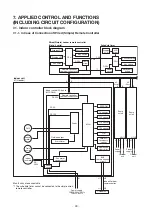
Page 30: ...motor Indoor fan motor CPU DC5V DC5V 1 CN2 CN1 Wired Simple header remote controller Up to 2 units Schedule timer Function setup LCD driver CPU Power circuit EEPROM TA sensor TC1 sensor TC2 sensor TCJ sensor HA Wireless Occupancy sensor Application control kit Outdoor unit Fan motor control circuit Start Alarm BUS communication circuit Power circuit Power circuit Remote controller communication ci...

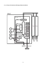
Page 31: ...tor control circuit Start Alarm BUS communication circuit MCU EEPROM TA sensor TC1 sensor TC2 sensor TCJ sensor HA Wireless Occupancy sensor Application control kit Driver Remote controller communication circuit DC 280V Indoor unit 1 Header Indoor fan motor U1 U2 U1 U2 Power supply 1Ø220 240V 50Hz 1Ø220V 60Hz Power supply Power supply Indoor Outdoor communication Outdoor unit 2 3 Follower Follower...

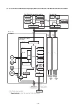
Page 32: ...220 240V 50Hz 1Ø220V 60Hz Indoor Outdoor communication Louver motor Drain pump Indoor fan motor Wired Simple header remote controller Schedule timer LCD driver Power circuit EEPROM TA sensor TC1 sensor TC2 sensor TCJ sensor HA Wireless Occupancy sensor Application control kit Outdoor unit Fan motor control circuit Start Alarm BUS communication circuit Power circuit Power circuit Remote controller ...

Page 33: ...Red DC12V 5V Output for FS unit CN81 Black DC12V TC2 sensor CN101 Black DC5V Drain pump CN504 White D12V TA sensor CN104 Yellow DC5V Grille up down CN20 Brue CHK CN71 White DC5V DISP CN72 White DC5V TCJ sensor CN102 Red DC5V Float SW CN34 Red DC12V HA T10 CN61 Yellow DC12V Wireless remote control or Occupancy sensor CN214 White DC fan motor CN210 White Ventilation output CN32 White D12V TC1 sensor...

Page 34: ...tor Operation ON Answer back of HA 5 DC12V 6 Warning output Open collector Warning output ON CHK Operation check CN71 1 This check is used to check indoor operation Performs operation of indoor fan H Louver horizontal and Drain pump ON without communication with outdoor and remote controller 2 0V DISP Exhibition mode CN72 1 Communication is available by indoor unit and remote controller only 2 0V ...

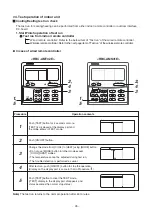
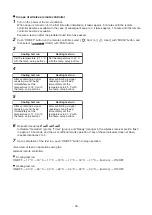
Page 35: ...r 4 seconds or more TEST is displayed at the display part and the mode enters in TEST mode Push ON OFF button Change the mode from COOL to HEAT using MODE button Do not use MODE button for other mode except COOL HEAT modes The temperature cannot be adjusted during test run The trouble detection is performed as usual After test run push ON OFF button to stop the operation Display on the display par...

Page 36: ...re to 18 C with the temp setup buttons After confirming a signal receiving sound beep immediately set the temperature to 29 C with the temp setup buttons Cooling test run Heating test run After confirming a signal receiving sound beep Immediately set the temperature to 17 C with the temp setup buttons After confirming a signal receiving sound beep immediately set the temperature to 30 C with the t...

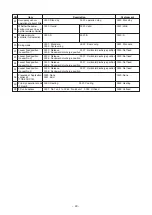
Page 37: ...hort circuiting DISP pin CN72 on the indoor P C board in addition to short circuit of CHK pin CN71 on the indoor P C board the minimum opening degree 30 pls can be set to the indoor PMV only When open DISP pin the maximum opening degree 1500 pls can be obtained again How to clear Open CHK pin While the system is operating it stops once but automatically returns to operation after several minutes T...

Page 38: ...r unit Nos under group control is displayed in turn Then the fan and louver of the selected indoor unit move 3 Use the TEMP button to select the CODE No DN code of the desired function 4 Use the button to select the desired SET DATA associated with the selected function 5 Push the SET button The display changes from flashing to steady To change the selected indoor unit go back to step 2 To change ...

Page 39: ...00 Body TA sensor 0001 Remote controller sensor 0000 Body TA sensor 33 Temperature unit select 0000 C at factory shipment 0001 F 0000 C 31 Ventilating fan control 0000 Unavailable 0001 Available 0000 Unavailable B3 Soft cooling 0000 Unavailable 0001 Available 0001 Available 77 Dual set point 0000 Unavailable 0002 Available 0000 Unavailable 13 Indoor unit address 0001 No 1 unit 0064 No 64 unit to 0...

Page 40: ... at absent time 0000 Stand by 0001 operation stop 0000 Stand by F0 Swing mode 0001 Standard 0003 Cycle swing 0002 Dual swing 0001 Standard F1 Louver fixed position Louver No 1 0000 Release 0005 Downward discharge position 0001 Horizontal discharge position 0000 Not fixed F2 Louver fixed position Louver No 2 0000 Release 0005 Downward discharge position 0001 Horizontal discharge position 0000 Not f...

Page 41: ...1 0003 0005 0007 0009 Capacity Invalid 005 type 007 type 009 type 012 type 015 type 018 type Value 0014 Type Model Compact 4 way Cassette MMU AP MH Indoor Unit Capacity DN code 11 1 Default value stored in EEPROM mounted on service P C board ...

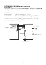
Page 42: ... operation 3 Check code Output present while alarm e g serial communication trouble or operation of protective device for indoor outdoor unit being activated Wiring diagram of control system using remote controller interface TCB IFCB 4E2 Input IFCB 4E2 No voltage ON OFF serial signal Output No voltage contact in operation and check code indication Contact capacity Max AC 240 V 0 5 A 1 2 3 4 5 6 CN...

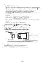
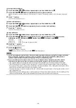
Page 43: ...he group control In this time the fan of the selected indoor unit turns on 2 Every pushing UNIT LOUVER button left side of the button the indoor unit numbers in group control are displayed successively In this time the fan of the selected indoor unit only turns on 3 Using the setup temp or button specify the CODE No 31 31 31 31 31 4 Using the timer time or button select the SET DATA At shipment 00...

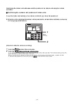
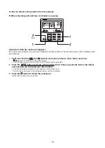
Page 44: ...prohibited to remote controller Status that card is taken out from the card switch box When the card switch box does not perform the above contact operation convert it using a relay with b contact 2 Operation Handle the wired remote controller switch in the following procedure Use the wired remote controller switch during stop of the system 1 Push concurrently SET CL buttons for 4 seconds or more ...

Page 45: ... before address setting Pair the indoor unit to set and the remote controller one to one Turn on the power 1 Push and hold the SET CL and buttons at the same time for more than 4 seconds LCD starts flashing Outdoor unit Remote controller Indoor unit 1 Refrigerant line 1 Refrigerant line 2 Indoor unit 2 Indoor unit 3 Outdoor unit Indoor unit 1 Indoor unit 2 1 Line system address 1 1 2 2 1 Indoor un...

Page 46: ... can control the unit after SETTING has disappeared NOTE 1 Do not use address numbers 29 or 30 when setting system addresses using the remote controller These 2 address numbers cannot be used on outdoor units and the CODE No E04 Indoor outdoor communication trouble will appear if they are mistakenly used 2 If you set addresses to indoor units in 2 or more refrigerate lines manually using the remot...

Page 47: ...e running 1 Push the ON OFF button if the units stop 2 Push the UNIT LOUVER button left side of the button A unit numbers 1 1 1 1 1 1 1 1 1 1 is indicated on the LCD it will disappear after a few seconds The indicated number shows the system address and indoor unit address of the unit When 2 or more indoor units are connected to the remote controller group controlled units a number of other connec...

Page 48: ...pears on UNIT No on the LCD display The fans and louvers of all the indoor units in the group are activated 2 Push the UNIT LOUVER button left side of the button Each time you push the button the indoor unit numbers are indicated one after another The first indicated unit number is the address of the header unit Only the fan and louvers of the indicated indoor unit are activated 3 Push the button ...

Page 49: ...utdoor unit 2 Push the UNIT LOUVER button left side of the button and SWING FIX buttons repeatedly to select a system address 3 Push the SET button to confirm the system address selection The address of an indoor unit connected to the selected refrigerant line is indicated on the LCD display and its fan and louvers are activated 4 Push the UNIT LOUVER button left side of the button Each time you p...

Page 50: ...d UNIT No is that of the head unit 2 Push the UNIT LOUVER button left side of the button repeatedly to select an indoor unit number to change if 2 or more units are controlled in a group The fan and louvers of the selected indoor unit are activated The fan of the selected indoor unit is turned on 3 Push the TEMP buttons repeatedly to select13 13 13 13 13 for CODE No 4 Push the TIME buttons repeate...

Page 51: ...e following step 2 Execute it while the units are stopped 1 Push and hold the TIME buttons at the same time for more than 4 seconds At first the line 1 and CODE No AC AC AC AC AC Address Change are indicated on the LCD display 2 Push UNIT LOUVER button left side of the button and SWING FIX buttons repeatedly to select a system address 3 Push the SET button The address of one of the indoor units co...

Page 52: ... confirm the new address on SET DATA 6 Push the UNIT LOUVER button left side of the button repeatedly to select another address to change Each time you push the button the indoor unit numbers in a refrigerant line are indicated one after another Only the fan and louvers of the selected indoor unit are activated Repeat steps 4 to 6 to change the indoor unit addresses so as to make each of them uniq...

Page 53: ...E No to FF 3 The display in A of the following figure counts down as follows at 5 second intervals 0005 0005 0005 0005 0005 0004 0004 0004 0004 0004 0003 0003 0003 0003 0003 0002 0002 0002 0002 0002 0001 0001 0001 0001 0001 0000 0000 0000 0000 0000 The check code is cleared when 0000 0000 0000 0000 0000 appears However the display counts down from 0005 0005 0005 0005 0005 again 4 Push the to retur...

Page 54: ...troller indoor unit and outdoor unit 1 Push and hold the and CL for 4 seconds or longer to enter the service monitoring mode The service monitor lights up The temperature of CODE No 00 00 00 00 00 appears at first 2 Push the TEMP button to change to CODE No of the item to monitor Refer to the following table for CODE No 3 Push the left part of the UNIT LOUVER button left side of the button to chan...

Page 55: ...7 77 rps 59 69 79 mode 5A 6A 7A 㷄 5B 6B 7B 㷄 5D 6D 7D 㷄 5E 6E 7E 㷄 5F 6F 7F HP Unit Outdoor unit individual data 3 5 90 Heating cooling recovery controlled 0 Normal 1 Recovery controlled 0010 Heating recovery controlled 0001 Cooling recovery controlled 91 Pressure release 0 Normal 1 Release controlled 0010 Pressure release controlled 92 CODE No Data name Display format Remote controller display ex...

Page 56: ...ssary e s u a c e l b i s s o P r o i v a h e B O N 1 A compressor would not start Could it just be the 3 minute delay period 3 minutes after compressor shutdown Could it just be the air conditioner having gone thermostats OFF Could it just be the air conditioner operating in fan mode or put on the timer Could it just be the system going through initial communication 2 An indoor fan would not star...

Page 57: ...F02 ALT Indoor heat exchanger temperature sensor TC2 check code Heat exchanger temperature sensor TC2 has been open shortcircuited F03 ALT Indoor heat exchanger temperature sensor TC1 check code Heat exchanger temperature sensor TC1 has been open shortcircuited F10 ALT Ambient temperature Ambient temperature sensor TA has been open shortcircuited sensor TA check code F11 ALT Discharge temperature ...

Page 58: ... connected to remote control communication line C12 Blanket alarm for general purpose device control interface Device connected to general purpose device control interface for TCC LINK is failure P30 As per alarm unit see above Group control follower unit trouble Group follower unit is failure unit No and above detail displayed on main remote control Operation Timer Ready Check code detected by ce...

Page 59: ...oor unit from other refrigerant line E20 Connection to other refrigerant line found during automatic address setting Indoor unit from other refrigerant line is detected while indoor automatic address setting is in progress E23 E23 Outdoor outdoor communication transmission trouble Signal cannot be transmitted to other outdoor units E25 E25 Duplicated follower outdoor address There is duplication i...

Page 60: ...has been detected H16 01 TK1 oil circuit trouble 02 TK2 oil circuit trouble 04 TK4 oil circuit trouble 05 TK5 oil circuit trouble H16 Oil level detection circuit trouble No temperature change is detected by temperature sensor for oil level detection TK1 TK2 TK4 TK5 despite compressor having been started M I S 4 0 L 4 0 L Duplicated outdoor refrigerant line address Identical refrigerant line addres...

Page 61: ...ndoor unit T L A 3 1 P 3 1 P Outdoor liquid backflow detection trouble State of refrigerant cycle circuit indicates liquid backflow operation P15 01 TS condition 02 TD condition n o i t c e t e d k a e l s a G T L A 5 1 P Outdoor suction temperature sensor TS1 detects sustained and repeated high temperatures that exceed standard value T L A 7 1 P 7 1 P Outdoor discharge TD2 temperature trouble Out...

Page 62: ...pressor 2 H03 Current detection circuit trouble Abnormal current is detected while inverter compressor is turned off P04 01 Compressor 1 02 Compressor 2 T L A 4 0 P Activation of high pressure SW High pressure SW is activated P07 01 Compressor 1 02 Compressor 2 T L A 7 0 P Heat sink overheating trouble Temperature sensor built into IPM TH detects overheating or has been short circuited P22 0 Eleme...

Page 63: ... the procedure described below 2 Trouble history The trouble history access procedure is described below up to four check codes stored in memory Check code history can be accessed regardless of whether the air conditioner is in operation or shut down Procedure To be performed when system at rest 1 Invoke the SERVICE CHECK mode by pressing the buttons simultaneously and holding for at least 4 secon...

Page 64: ...nication trouble P01 Indoor AC fan trouble P10 Indoor overflow trouble P12 Indoor DC fan trouble P13 Outdoor liquid backflow detection trouble P03 Outdoor discharge TD1 temperature trouble P04 Activation of outdoor high pressure SW P05 Open phase power failure Inverter DC voltage Vdc trouble MG CTT trouble P07 Outdoor heat sink overheating trouble Poor cooling of electrical component IGBT of outdo...

Page 65: ...sor TD1 H06 Abnormal drop in low pressure sensor Ps reading Protective shutdown of outdoor unit H07 Abnormal drop in oil level H08 Trouble in temperature sensor for oil level detection circuit TK1 TK2 TK3 TK4 or TK5 H15 Wiring installation trouble or detachment of outdoor discharge temperature sensor TD2 H16 Oil level detection circuit trouble Trouble in outdoor unit TK1 TK2 TK3 TK4 or TK5 circuit...

Page 66: ...peration Timer Synchronized blinking Ready Alternate blinking Operation Timer Ready Light block Check code Cause of trouble Communication trouble between indoor unit s and FS unit s FS unit s system trouble Operation Timer Blinking Ready Synchronized blinking Operation Timer Ready Duplicated FS units E17 L12 FS unit s setting trouble L24 J03 FS unit overflow trouble J10 FS unit temperature sensor ...

Page 67: ...ck order in which power was turned on for indoor and outdoor units Check indoor address setting Check indoor outdoor tie cable Check outdoor terminator resistor setting SW30 Bit 2 E04 I F Indoor outdoor communication circuit problem detected at outdoor end All stop Signal cannot be transmitted from outdoor to indoor units for 30 seconds continuously Check outdoor terminator resistor setting SW30 B...

Page 68: ...indoor header and follower units Stop of corresponding unit Periodic communication between indoor header and follower units cannot be maintained E18 Outdoor header unit is outdoor unit to which indoor outdoor tie cable U1 U2 is connected Check connection of indoor outdoor communication line Check for defect in outdoor P C board I F I F 00 No header unit 02 Two or more header units Problem in numbe...

Page 69: ... functions If SW04 is pressed and held for at least 1 second while E28 is displayed on the 7 segment display of outdoor header unit the fan of the outdoor unit that has been shut down due to a trouble comes on If SW04 and SW05 are pressed simultaneously the fans of normal outdoor units come on To stop the fan or fans press SW05 on its own E28 E28 I F IPDU communication problem All stop Communicati...

Page 70: ...short circuit F10 Check connection of TE1 TE2 sensor connectors Check resistance characteristics of TE1 TE2 sensors Check for defect in outdoor P C board I F I F 01 TE1 sensor problem 02 TE2 sensor problem TE1 TE2 sensor problem All stop Sensor resistance is infinity or zero open short circuit F06 F06 Check connection of TG1 TG2 sensor connectors Check resistance characteristics of TG1 TG2 sensors...

Page 71: ...ro sensor open circuited Pd 4 15MPa despite compressor having been turned off F24 F24 Check for defect in indoor P C board failure EEPROM Indoor unit Other indoor problem Stop of corresponding unit Indoor P C board does not operate normally F29 Check power supply voltage Check power supply noise Check for defect in outdoor P C board I F I F Outdoor EEPROM problem All stop 1 Outdoor P C board I F d...

Page 72: ...cteristics of TD1 sensor Check for defect in outdoor P C board I F I F TD1 sensor miswiring incomplete insertion All stop Discharge temperature of compressor 1 TD1 does not increase despite compressor being in operation H05 H05 Check service valves to confirm full opening both gas and liquid sides Check outdoor PMVs for clogging PMV1 3 Check for defect in SV2 or SV4 circuits Check for defect in lo...

Page 73: ...r P C board I F I F 01 TK1 sensor problem 02 TK2 sensor problem 04 TK4 sensor problem 05 TK5 sensor problem Trouble in temperature sensor for oil level detection All stop Sensor resistance is infinity or zero open short circuit H08 H08 Check connection of TK2 sensor connector Check resistance characteristics of TK2 sensor Check for defect in outdoor P C board I F All stop Sensor resistance is infi...

Page 74: ... address setting for outdoor units belonging to different refrigerant piping systems L04 L04 Check display on priority indoor unit I F Duplicated priority indoor unit as displayed on priority indoor unit All stop More than one indoor units have been set up as priority indoor unit L05 Check for disconnection of TK2 sensor Check resistance characteristics of TK2 sensor Check for connection trouble i...

Page 75: ...ck network adaptor P C board L20 I F SW setting mistake All stop Outdoor P C board I F does not operate normally Check switch setting of Bit 3 and 4 of SW17 in outdoor P C board I F L23 I F Extended IC problem Continued operation There is part failure in P C board I F Check outdoor P C board I F L31 Indoor unit Indoor fan motor problem Stop of corresponding unit Check the lock of fan motor AC fan ...

Page 76: ...ressure sensor Check outdoor service valves gas side liquid side to confirm full opening Check for defect in outdoor fan Check for defect in outdoor fan motor Check outdoor PMVs PMV1 3 for clogging Check indoor outdoor heat exchangers for clogging Check for short circuiting of outdoor suction discharge air flows Check SV2 circuit for clogging Check for defect in outdoor P C board I F Check for tro...

Page 77: ...or 3 continuously registers opening of 300p or less while under superheat control P13 P13 Check for insufficiency in refrigerant quantity Check outdoor service valves gas side liquid side to confirm full opening Check PMVs PMV1 3 for clogging Check resistance characteristics of TS1 sensor Check for defect in 4 way valve Check SV4 circuit for leakage I F 01 TS condition Gas leakdetection TS1 condit...

Page 78: ...k for defect in outdoor fan motor Check outdoor PMV PMV1 3 4 for clogging Check indoor outdoor heat exchangers for clogging Check for short circuiting of outdoor suction discharge air flows Check SV2 circuit for clogging Check for defect in outdoor P C board I F Check for defect in indoor fan system possible cause of air flow reduction Check opening status of indoor PMV Check indoor outdoor commun...

Page 79: ... Check fan motor Check connection of fan motor connector Check for defect in fan IPDU P C board 1 Position detection circuit problem All stop Sub code 1 Fan IPDU position detection circuit Position detection is not going on normally Check fan motor Check for defect in fan IPDU P C board 3 Motor lock problem All stop Sub code 3 Gusty wind an obstruction or another external factor Speed estimation i...

Page 80: ...P C boards of devices at other end of central control communication line TCC LINK central control device reception problem Continued operation Central control device is unable to receive signal C06 Check problem input General purpose device I F Blanket alarm for general purpose device control interface Continued operation Trouble signal is input to control interface for general purpose devices C12...

Page 81: ...e indoor P C board MCC 1643 Check the indoor P C board MCC 1643 If failure Replace Disconnect the connector CN210 to the indoor P C board Is not connection trouble or disconnection on the connector CN210 of indoor unit P C board Does the fan turn smoothly when turned by hand Is each resistance value on the motor side of the fan motor connector CN210 of the indoor P C board correct Is F01 of the in...

Page 82: ...rd not illuminated Red LED LD1 light on the external input output board flashes on and off Red LED LD1 of external input output board blinks Repair of connector connection Check the operating status Yes Yes Yes Yes No No No No Replacement of the connectorfs lead wire Lead wire is cut or failure of input output board Failure with the external input output board Replace Failure with the external inp...

Page 83: ... Correct the connector connection Is DN code B5 setup By the wired remote controller change the enable DN code B5 from 0000 0001 Check the indoor main P C board MCC 1643 Failure Exchange No Yes Is the Occupancy sensor unit normal Exchange the Occupancy sensor unit No Yes No Yes ...

Page 84: ...elss remote controller at the first time after install RBC AX32UM Is connection of lead wire between CN214 of indoor P C board and RBC AX32UM correct Repair the connection Replace the RBC AX32UM Yes No Does wireless remote controller operate Replace the indoor P C board MCC 1643 No No Yes End Yes ...

Page 85: ...0 0 8 1 6 5 5 3 4 4 3 6 3 0 2 5 2 1 1 8 1 5 1 3 1 1 1 0 0 8 0 7 Temperature C Temperature C 20 15 10 5 0 5 10 15 20 25 30 35 40 45 50 55 60 65 70 75 80 85 90 95 100 Indoor TC1 sensor 20 10 0 10 20 30 40 50 60 70 80 90 100 50 100 150 200 5 10 15 20 30 0 0 Resistance kΩ 10 C or below Resistance kΩ 10 C or above Resistance kΩ 115 2 84 2 62 3 46 6 35 2 26 9 20 7 16 1 12 6 10 0 8 0 6 4 5 2 4 2 3 5 2 8 ...

Page 86: ...ailure to clean the indoor outdoor units regularly will cause shortage of capacity freezing water leakage or trouble on the compressor Part name Object Contents of check Contents of maintenance Indoor Outdoor Heat exchanger Blocking with dust damage check Clean it when blocking is found Fan motor Audibility for sound When abnormal sound is heard Filter Visual check for dirt and breakage Clean with...

Page 87: ...nit settings and perform the cooling cycle confirmation through the trial operation Replacement procedures CASE 1 Before replacement the indoor unit can be turned on and the setting data can be read out by wired remote control operation EEPROM data read out 1 Ø Replacement of P C board for Indoor unit servicing and power on 2 Ø Writing the read out EEPROM data 3 Ø Power reset for all indoor units ...

Page 88: ...us It takes approx 1 min until the remote controller operation is available again 1 The CODE No for the Indoor unit type and Indoor unit capacity are required to set the rotation number setting of the fan 2 If the system indoor group addresses are different from those before replacement the auto address setting mode starts and the manual resetting may be required again when the multiple units grou...

Page 89: ...e the factory set values Step 1 Push SET CL and buttons on the remote controller simultaneously for more than 4 seconds In the group control operation the unit No displayed for the first time is the header unit No At this time the CODE No DN shows 10 Also the fan of the indoor unit selected starts its operation and the swing operation starts if it has the louvers The unit No ALL is displayed if th...

Page 90: ... the temperature setting As described above check the setting data and modify to the data put down in 1 Step 8 Repeat the steps 6 and 7 Step 9 After the setting completes push button to return to the normal stop status It takes approx 1 min until the remote controller operation is available again The CODE No DN are ranged from 01 to FF The CODE No DN is not limited to be serial No Even after modif...

Page 91: ... 77 Dual set point 0000 Unavailable B3 Soft cooling 0001 Available Fd Priority operation mode FS unit 0000 Heating FE FS unit address 0099 Unfixed B5 Occupancy sensor Provided None 0000 None B7 Occupancy sensor Operation at absent time 0000 Stand by 31 Ventilation fan standalone 0000 Not available 32 Sensor SW Selection of static pressure 0000 Body sensor 60 Timer setting wired remote controller 0...

Page 92: ...the ceiling panel while the air intake grille is opened 2 Attachment 1 Hook the hinge of the air intake grille to the main panel and then attach the fall preventive strap 2 Close the air intake grille and then slide the hook 3 Slide the grille fixing bracket to fix it with the screws Ø4 8 1pc Hook of fall preventive strap Hook hole of ceiling panel Hinge Hinge Fall preventive strap Fixing bracket ...

Page 93: ...body to the bell mouth 2 Connect the louver motor connectors at the ceiling panel side and the indoor unit side 3 Lift up the panel corner part and put out the screw head of the panel fixed implement Slide the panel fixed bracket and then fix the indoor unit and the ceiling panel Total 4 positions In case of loosening screws of the panel fixed implement so that screw head is out under the panel fi...

Page 94: ... the wires with clamps 3 Following to the work in d 2 attach the electric parts covers as original h Turbo fan 1 Detachment 1 Remove the air intake grille Refer to 1 of c 2 Loosen the fix screws 2 positions of the bell mouth rotate the bell mouth and then take off it Ø4 10 2 pcs 3 Loosen the flange nut M8 at the center part of the turbo fan and then take off Counter clockwise Supporting with hands...

Page 95: ...f the drain pan fixing bracket Ø4 8 4 pcs 7 Using the both hands hold the water spilling port part of the drain pan and then slowly pull out the foaming parts firstly As there is remained water in the drain pan clear it carefully 2 Attachment 1 Arrange direction of the drain pan directly to the foaming parts and insert it Pass the fan motor lead wire through the inner side of the drain pan 2 Attac...

Page 96: ...drain pump wiring through side plate and clamp and then connect the connector to the control P C board 4 Following to work in i 2 attach the drain pan panel and electrical parts covers as original k Float switch 1 Detachment 1 Remove the drain pan Refer to i 1 2 Remove the float switch connector CN34 3P Red connected to the control P C board and then take off the lead wires from the clamp 3 Remove...

Page 97: ...ng plate removed in 1 3 and then fix it with shoulder screw 3 Perform wiring of the motor lead wires as original connect the connector to the control P C board and then attach the wiring fixing plate and the wiring cover 4 Following to works in h 2 and d 2 attach the turbo fan and the electric parts covers PMV motor 1 Detachment 1 Remove the drain pan Refer to i 1 2 Remove the PMV connectors CN82 ...

Page 98: ... fixing plate Refer to f 1 d 1 i 1 2 i 1 3 2 Disconnect TA sensor connector CN104 Yellow 2P which is connected to the control P C board and take off the lead wire from the clamp 3 Remove the screw of the TA sensor cover Ø4 10 1pc 4 Remove TA sensor from the TA sensor fixed implement 2 Attachment 1 Fix TA sensor to TA sensor fixing implement and fix the TA sensor cover with screw Ø4 10 1 pc 2 Perfo...

Page 99: ...he heat exchanger so that it will not be fallen down Take note that you will not get hurt by touching to Aluminum fin Be sure to put on the protective gloves and the safety working clothing 2 Attachment 1 Attach the heat exchanger as original with the separate plate and the fixing plate 2 Slide the piping cover to the groove fix it to the side plate and then use the screws Ø4 8 3 pcs 3 Perform wir...

Page 100: ... 100 11 EXPLODED VIEWS AND PARTS LIST MMU AP0057MH E TR AP0077MH E TR AP0097MH E TR AP0127MH E TR ...

Page 101: ... 101 MMU AP0157MH E TR AP0187MH E TR ...

Page 102: ...FRIGERATION CYCLE ASSY REFRIGERATION CYCLE ASSY REFRIGERATION CYCLE ASSY NUT FLARE 1 4 IN SOCKET 3 8 IN SOCKET 1 4 IN NUT FLARE 1 2 IN SOCKET 1 2 IN BONNET 3 8 IN BONNET 1 2 IN BONNET 1 4 IN HOSE DRAIN BAND HOSE HOLDER LEAD FAN MOTOR HOSE DRAIN COVER PIPE NUT HOLDER SENSOR HOLDER SENSOR TS BAND HOSE SHEET PMV RUBBER CUSHION COVER E BOX PUMP DRAIN SWITCH FLOAT REMOTE CONTROLLER SX A4EE REMOTE CONTR...

Page 103: ...6 4316V592 43459017 43F50426 43163057 43163058 SENSOR ASSY SERVICE TC F6 SENSOR ASSY SERVICE TG F4 TERMINAL 4P TERMINAL BLOCK 2P 20A PC BOARD ASSY MCC 1643 PC BOARD ASSY TCB PCUC1E SENSOR SERVICE TA CLAMP DOWN CLAMP UP 2 1 1 1 1 1 1 1 1 0077 2 1 1 1 1 1 1 1 1 0057 2 1 1 1 1 1 1 1 1 2 1 1 1 1 1 1 1 1 2 1 1 1 1 1 1 1 1 2 1 1 1 1 1 1 1 1 Description ...

Page 104: ...4310A143 43107298 43107299 43107300 43107301 43107302 43107303 43160664 4310A144 43419022 43107304 43107305 GRILLE AIR INLET AIR FILTER MOTOR LOUVER MSBPC20F04 OUTLET AIR FORM OUTLET AIR FORM LOUVER ASSY COVER PANEL ASSY COVER PANEL ASSY PLATE FIX PANEL A PLATE FIX PANEL B HOOK CAP AXIS FIX MOTOR ASSY FIX MOTOR ASSY LEAD MOTOR PANEL HINS ASSY STRING HANGER FIX GRILLE 1 1 4 4 4 4 3 1 2 2 2 4 2 2 1 ...

Page 105: ...BC AX32UM W E Part No Description 351 352 353 354 355 356 357 4316V616 43162088 43108036 43160665 43408061 43166018 43F83071 PC BOARD ASSY REMOTE RECIEVER COVER WRS COVER PANEL WRS LEAD COVER WIRELESS REMOTE CONTROLLER WIRELESS WH L11SE HOLDER REMOTE CONTROLLER 1 1 1 1 1 1 1 ...

Page 106: ...pancy sensor TCB SIR41UM E Location No Q ty Set TCB SIR41UM E Part No Description 361 362 363 364 365 43162088 43108037 43160666 43408062 43469067 COVER WRS COVER PANEL WRS LEAD COVER SENSOR THERMOSTAT 1 1 1 1 1 ...

Page 107: ... 72 34 Horikawa cho Saiwai ku Kawasaki shi Kanagawa 212 8585 JAPAN Copyright 2017 TOSHIBA CARRIER CORPORATION ALL Rights Reserved Revision record First issue Jan 2017 Revision 1 The item of CODE NO C2 was deleted Page 91 Jun 2017 ...

Reviews: