45
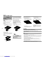
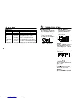
• About “Dual swing”
“Dual” means that louvers
01
and
03
are directed
and swing in one direction and louvers
02
and
04
are directed and swing in the opposite
direction.
(When louvers
01
and
03
are directed downward,
louvers
02
and
04
are directed holizontally.)
• About “Cycle swing”
The four louvers swing independently at
respective timings.
4. Push
SET
button.
5. Push
TEST
button to complete the setting.
n
How to set up louver lock (No swing)
1. Push
UNIT LOUVER
(right side of the button) for at
least four seconds when the air conditioner is
not working.
SETTING
flashes.
Indicates CODE No. [F1].
2. Select an indoor unit to be set by pushing XX
(left side of the button).
Each time you push the button, unit numbers
change as follows: The fan of the selected
unit runs and the louvers start swinging.
3. Select a louver you want to lock by pushing
“TEMP.
/
” buttons.
4. Select the wind direction of the louver you do
not want to swing by pushing “TIME
/
”
buttons.
∗
When (4) or (5) is selected, dew drop may
occur during cooling mode.
5. Determine the setting by pushing
SET
button.
When the setting has been determined,
lights up.
6. Push
TEST
button to complete the setting.
n
How to cancel louver lock
Set the wind direction to “0000” of the louver
lock setup procedure above.
n
Remote controller sensor
The temperature sensor of the indoor unit
senses room temperature usually.
Set the remote controller sensor to sense the
temperature around the remote controller.
Select items following the basic operation
procedure (
1
→
2
→
3
→
4
→
5
→
6
).
• Specify [32] for the CODE NO. in Procedure
3
.
• Select the following data for the SET DATA in
Procedure
4
.
• When the setting is canceled,
goes out.
Other operations are the same as those in
“How to set up louver lock (No swing)”.
n
Group control
In a group control, a remote controller can
control up to maximum 8 units.
• For wiring procedure and wiring method of
the individual line (Identical refrigerant line)
system, refer to “Electric work” in this Manual.
• Wiring between indoor units in a group is
performed in the following procedure.
Connect the indoor units by connecting the
remote controller inter-unit wires from the
remote controller terminal blocks (A/B) of the
indoor unit connected with a remote control-
ler to the remote controller terminal blocks
(A/B) of the other indoor unit. (Non-polarity)
• For address setup, refer to the Installation
Manual attached to the outdoor unit.
When
flashes, the remote controller sensor
is defective.
Select the SET DATA [0000] (not used) or
replace the remote controller.
SET DATA
Remote controller
sensor
0000
Not used
(factory setting)
0001
Used
8
APPLICABLE CONTROLS
Unit No.
1-2
Unit No.
1-4
Unit No.
1-3
No display
Unit No.
1-1
Refrigerant
pipe
Drain pipe
Electric parts box
01
03
04
02
SET DATA
(1)
0001
(2)
0002
(4)
0004
(5)
0005
(3)
0003
0001 – 0005
(Louver lock position code)
Setting data
0000

