108
No.
Part name
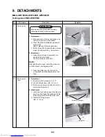
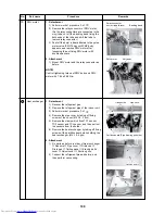
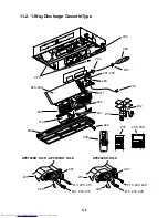
Drain pump
Procedure
1. Detachment
1) Perform work of procedure 1. of
.
2) Remove clamps of the lead wires con-
nected to the following connectors of the
control P.C. board.
NOTE)
Be sure to unlock the lock of the housing before
removing the connector.
CN34: Float switch (3P: Red)
CN68: Drain pump (3P: Blue)
3) Pick the hose band and shift band from
pump connecting part to remove the drain
hose.
4) Take off screws fixing the drain pump
assembly. (Ø4 × 8, 3 pcs)
5) Pull out the drain pump assembly toward
discharge side to remove it.
2. Attachment
1) Fix the drain pump assembly as before.
2) Connect the drain hose and attach the
hose band.
NOTE)
Insert the drain hose completely up to the end of
the pump connecting part, and then attach band
at the white mark position of the hose.
3) Insert the connectors to the control P.C.
board as before.
4) Fix parts as before in order of Drain cap
→
Drain pan
→
Ceiling panel
→
Electric parts
cover
→
Adjust cover
→
Suction grille.
Remarks
CN68
Shift the band toward hose side.
CN34
Hose band
Fixing screw
Pull out toward discharge side.
Summary of Contents for MMU-AP0152SH
Page 20: ......
Page 21: ......
Page 22: ......
Page 23: ......
Page 24: ......
Page 25: ......
Page 26: ......
Page 27: ......
Page 28: ......
Page 29: ......
Page 30: ......
Page 31: ......
Page 32: ......
Page 33: ......
Page 34: ......
Page 53: ......
Page 54: ......
Page 55: ......
Page 56: ......
Page 57: ......
Page 58: ......
Page 59: ......
Page 60: ......
Page 61: ......
Page 62: ......
Page 63: ......
Page 64: ......
Page 65: ......
Page 67: ......
Page 68: ......
Page 69: ......
Page 70: ......
Page 71: ......
Page 72: ......
Page 73: ......
Page 74: ......
Page 75: ......
Page 76: ......
Page 77: ......
Page 78: ......
Page 79: ......
Page 80: ......
Page 81: ......
Page 82: ......
Page 83: ......
Page 84: ......
Page 85: ......
Page 86: ......
Page 87: ......
Page 88: ......
Page 89: ......
Page 90: ......
Page 91: ......


