background image

8

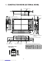
1. CONSTRUCTION VIEWS (EXTERNAL VIEWS)

16

120

4

2.7

120

• Wired remote controller 

(RBC-AMT31E)

Drain pipe connecting port
(Be sure to connect the attached flexible hose.)

Wire inlet

112

252

94

154

72

20

20

20

20

C/L

C/L

233

73.4

76

43

60

80

216

200

20

93

122

56

248

Wire inlet (Knockout hole)

Fresh air inlet (Ø92 knockout hole)

Ø112 (4-tapping screw under-hole)

710  Unit external size

1060  Hanging bolt pitch

1190  Ceiling opening size

1230  Panel external size

1000  Unit external size

475  Hanging bolt pitch

135

100

220

760  Ceiling opening size

800  Panel external size

706

Lower surface of ceiling

Ceiling panel (Sold separately)

For front air discharge unit (Sold separately) knockout hole

Hanging bolt M10 or W3/8 (Local supply)

Refrigerant pipe connecting port
Gas side B

Refrigerant pipe connecting port
Liquid side A

Model name   MMU-

AP015, AP018 type  

AP024 type

A

Ø6.4

Ø9.5

B

Ø12.7

Ø15.9

Summary of Contents for MMU-AP0152SH

Page 1: ...MANUAL 1 Way Discharge CassetteType MMU AP0152SH AP0152SH K MMU AP0182SH AP0182SH K MMU AP0242SH AP0242SH K This Service Manual describes contents of the new 1 Way Discharge Cassette indoor unit For the outdoor unit refer to the Manual with FILE NO A03 009 ...

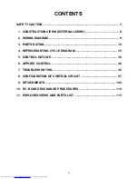
Page 2: ...2 WIRING DIAGRAM 9 3 PARTS RATING 10 4 REFRIGERANTING CYCLE DIAGRAM 35 5 CONTROL OUTLINE 36 6 APPLIED CONTROL 40 7 TROUBLESHOOTING 45 8 CONFIGURATION OF CONTROL CIRCUIT 97 9 DETACHMENTS 102 10 P C BOARD EXCHANGE PROCEDURES 110 11 EXPLODED VIEWS AND PARTS LIST 115 2 ...

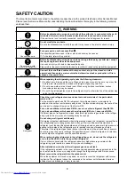
Page 3: ...which uses other refrigerant R22 etc never use R410A If different types of refrigerant are mixed abnormal high pressure generates in the refriger ating cycle and an injury due to breakage may be caused Do not charge refrigerant additionally If charging refrigerant additionally when refrigerant gas leaks the refrigerant composition in the refrigerating cycle changes resulted in change of air condit...

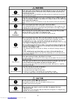
Page 4: ...cludes a large amount of charged refrigerant such as a multi air conditioner in a sub room it is necessary that the density does not the limit even if the refrigerant leaks If the refrigerant leaks and exceeds the limit density an accident of shortage of oxygen is caused For the installation moving reinstallation work follow to the Installation Manual If an incorrect installation is done a trouble...

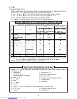
Page 5: ...others do not mix in because pipes are affected by impurities such as water oxide scales oil etc Use the clean pipes Be sure to brazing with flowing nitrogen gas Never use gas other than nitrogen gas 4 For the earth protection use a vacuum pump for air purge 5 R410A refrigerant is azeotropic mixture type refrigerant Therefore use liquid type to charge the refrigerant If using gas for charging comp...

Page 6: ...heck etc Vacuum evacuating Refrigerant charge Refrigerant charge Gas leakage check Refrigerant charge Conventional air conditioner installation Whether new equipment can be used with conventional refrigerant Yes Note 1 No No Yes Yes No Yes No Whether conven tional equipment can be used Note 1 Note 1 No No No Yes No No No 1 Vacuum pump Use vacuum pump by attaching vacuum pump adapter 2 Torque wrenc...

Page 7: ...d Brazed Service port Service port Ø6 4 Copper pipe Ø6 4 Copper pipe Fully tightened Fully tightened Reducing valve Nitrogen gas Valve fully closed liquid side Valve fully closed balance Connected to other terminal units Charge the refrigerant as below Recover the refrigerant and check there is no refrigerant in the equipment Leave it as it is for 1 to 2 minutes and check the indicator of the comp...

Page 8: ...rew under hole 710 Unit external size 1060 Hanging bolt pitch 1190 Ceiling opening size 1230 Panel external size 1000 Unit external size 475 Hanging bolt pitch 135 100 220 760 Ceiling opening size 800 Panel external size 706 Lower surface of ceiling Ceiling panel Sold separately For front air discharge unit Sold separately knockout hole Hanging bolt M10 or W3 8 Local supply Refrigerant pipe connec...

Page 9: ...d connector Flow selector unit earth screw 5 4 1 5 5 5 4 3 3 3 2 1 1 1 CN333 WHI Fuse T3 15A 250V CN82 BLU CN112 WHI CN111 WHI CN110 WHI CN71 CHK High ceiling setup LM CN33 WHI CN334 WHI FM 1 2 3 4 5 6 1 1 1 2 1 2 1 2 1 2 1 2 1 2 2 2 3 3 3 4 4 4 5 3 CN34 RED FS 1 2 3 1 3 4 5 1 2 3 4 5 1 2 3 4 5 1 2 3 4 5 5 5 6 6 6 PMV Motor drive circuit Fuse T6 3A 250V Power supply circuit DC20V DC15V DC12V DC7V ...

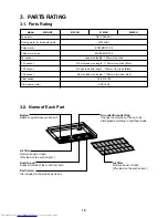
Page 10: ...mm Vinyl tube Blue Ø6 size lead wire length 1100mm Vinyl tube Black Ø6 size lead wire length 1100mm Vinyl tube Red FS 0218 103 ADP 1409 3 2 Name of Each Part Button Button to open close suction port Air outlet Air outlet flap Change the direction of the air to be discharged according to cool heat mode Air filter Removes dust or trash Provided on the suction port Suction port Sucks air inside of th...

Page 11: ...selected air volume mode is displayed AUTO HIGH MED LOW In the Concealed Duct High Static Pressure type models HIGH only is displayed for the air speed 16 Mode select control display Displayed when pushing Operation mode select button while the operation mode is fixed to heating or cooling by the system manager of the air condi tioner 17 Central control display Displayed when using the remote cont...

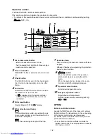
Page 12: ...e controller select the units when the air direction is adjusted SWING FIX Set up the auto swing and angle of the flap 7 Operation lamp Lamp is lit during the operation Lamp is off when stopped Although it flashes when operating the protection device or abnormal time 8 ON OFF button When the button is pushed the operation starts and it stops by pushing the button again When the operation has stopp...

Page 13: ...tton and the display changes in the order shown on the right In HEAT mode if the room temperature reaches to the set temperature the outdoor unit stops and the air flow becomes LOW and the air volume decreases In the defrost mode the fan stops so that cool air is not discharged and PRE DEF is displayed 3 Select air volume with FAN FAN button One push of the button and the display changes in the or...

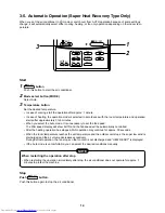
Page 14: ...n starts after approximately 3 to 5 minutes When you select the Auto mode it is unnecessary to set the fan speed The FAN speed display will show AUTO and the fan speed will be automatically controlled After the heating operation has stopped FAN operation may continue for approx 30 seconds When the room temperature reaches the set temperature and the outdoor unit stops the super low wind is dischar...

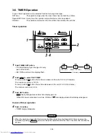
Page 15: ...of 0 5 hr 30 minutes The maximum set time is 72 0 hr For every push of button the set time decreases in the unit of 0 5 hr 30 minutes The minimum set time is 0 5 hr 3 Push SET button SETTING display disappears and timer time display goes on When ON timer is activated timer time ON timer are displayed and other displays disappear Cancel of timer operation 4 Push CL button TIMER display disappears N...

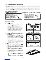
Page 16: ...upward If directing it downward the dew may fall on near the air air outlet port or it drips How to start swinging 2 Push SWING FIX button Set direction of the horizontal flap Up Down air direction adjustment plate to the lowest position and then push SWING FIX button again SWING is displayed and the air direction automatically changes upward downward In case when one remote controller controls th...

Page 17: ...ir conditioner If the protective device works the operation stops and the operation lamp flashes When the protective device works the indication TEST and the check code are displayed on the display section of the remote controller In the following cases the protective device may work In cooling operation The suction port or discharge port of the outdoor unit is closed A strong wind continuously bl...

Page 18: ...on the defrosted water will be drained from the bottom plate of the outdoor unit Heating capacity In the heating operation the heat is absorbed from the outside and brought into the room This way of heating is called heat pump system When the outside temperature is too low it is recommended to use another heating apparatus in combination with the air conditioner Attention to snowfall and freeze on...

Page 19: ...r HEAT and an operation contrary to the setup operation is performed When fan operation stopped to prevent discharge of hot air Since refrigerant is flowed temporarily to prevent stay of oil or refrigerant in the stand by indoor unit sound of flowing refrigerant Kyururu or Shaa may be heard or white steam when other indoor unit operates in HEAT mode and cold air in COOL mode may be blow out Sound ...

Page 20: ......

Page 21: ......

Page 22: ......

Page 23: ......

Page 24: ......

Page 25: ......

Page 26: ......

Page 27: ......

Page 28: ......

Page 29: ......

Page 30: ......

Page 31: ......

Page 32: ......

Page 33: ......

Page 34: ......

Page 35: ...l outline Connector CN082 6P Blue 1 Controls super heat in cooling operation 2 Controls under cool in heating operation 3 Recovers refrigerant oil in cooling operation 4 Recovers refrigerant oil in heating operation Connector CN104 2P Yellow 1 Detects indoor suction temperature Connector CN100 3P Brown 1 Controls PMV super heat in cooling operation Connector CN101 2P Black 1 Controls PMV under coo...

Page 36: ...r or central controller the operation mode is se lected 2 Operation select Concealed Duct High Static Pressure type air conditioner cannot operate for drying 3 1 Adjustment range Set temperature on remote controller C Wired type Wireless type Allcooling 18 to 29 C 18 to 30 C All heating 18 to 29 C 16 to 30 C 2 From the item code 06 the setup temperature in heating operation can be corrected Setup ...

Page 37: ... becomes S0 to the outdoor unit In K zone the timer count is interrupted and held When 1 zone is detected the timer is cleared and the operation returns to the normal operation When the command frequency became S0 with continua tion of J zone operation of the the indoor fan in LOW mode until it reaches the 1 zone It is reset when the following conditions are satisfied Reset conditions 1 TC1 12 C a...

Page 38: ...hermostat is OFF with even the above condition The protective control has priority 1 During COOL operation including DRY operation the drain pump operates 2 While the drain pump operates if the float switch works the drain pump continues operation and a check code is displayed 3 While the drain pump stops if the float switch works turn off the capacity demand command stop the operation and operate...

Page 39: ...scharge of cold draft or stops including case that defrost operation is being performed HEAT operation cannot be performed because COOL priority is set Outdoor I F P C board SW11 bit 1 is ON and the other indoor unit is under COOL DRY operation 2 HEAT standby is displayed until the above conditions are released Remarks goes on Item and display Operation and heating stand by goes on 16 Selection of...

Page 40: ... the group control are successively displayed In this time the fan of the selected indoor unit only is turned on 3 Specify the item code DN using the setup temperature and buttons 4 Select the setup data using the timer time and buttons When selecting the DN code to 33 change the temperature indication of the unit from C to F on the remote controller 5 Push SET button OK if display goes on To chan...

Page 41: ...ette to 0037 0000 Unfixed 0001 to 0034 0001 No 1 unit to 0030 No 30 unit 0001 No 1 unit to 0064 No 64 unit 0000 Individual 0001 Header unit of group 0002 Follower unit of group 0000 Not provided 0001 Swing only 0004 4 way Air Discharge Cassette type and Under Ceiling type 0000 0 deg to 0010 10 deg For setup temperature reversal of COOL HEAT by Data value 2 0000 None 0001 Restart 0000 Usual 0001 Co...

Page 42: ... individually 1 Control items 1 Start Stop input signal Operation start stop in unit 2 Operation signal Output during normal operation 3 Error signal Output during alarm Serial communication error or indoor outdoor protective device operation 2 Wiring diagram using remote control interface TCB IFCB 4E Input IFCB 4E No voltage ON OFF serial signal Output No voltage contact for operation error displ...

Page 43: ...the indoor unit numbers in group control are displayed succes sively In this time the fan of the selected indoor unit only turns on 3 Using the setup temp or button specify the item code 4 Using the timer time or button select the setup data At shipment The setup data are as follows Setup data Handling of operation of air to air heat exchanger or ventilating fan Unavailable At shipment Available 1...

Page 44: ...at card is taken out from the card switch box When the card switch box does not perform the above contact operation convert it using a relay with b contact 2 Operation Handle the wired remote controller switch in the following procedure Use the wired remote controller switch during stop of the system 1 Push concurrently SET CL TEST buttons for 4 seconds or more 2 Using the setup temp or button spe...

Page 45: ...tat OFF Is not the fan operating or timer Is not the system initially communicating Heating operation cannot be performed under condition of outside tempera ture 21 C or higher Cooling operation cannot be performed under condition of outside tempera ture 5 C or lower Is not the cold draft prevention being controlled in heating operation Is not low cooling operation being controlled Is not a defros...

Page 46: ...No of connected units E19 00 No header unit 02 Two or more header units E20 01 Outdoor of other line connected 02 Indoor of other line connected E23 E25 E26 No of outdoor units which received signal normally E28 Detected outdoor unit number 01 IPDU1 error 02 IPDU2 error 03 IPDU1 2 error E31 04 Fan IPDU error 05 IPDU Fan IPDU error 06 IPDU2 Fan IPDU error 07 All IPDU error AI NET central control di...

Page 47: ... F04 F05 F06 F07 F08 F10 F12 F13 F15 F16 F23 F24 F29 F31 H01 H02 H03 H04 H06 H07 H08 H14 H16 L03 L04 L05 L06 L07 L08 L09 L10 L17 L18 L20 L28 L29 L30 Outdoor 7 segment display Sub code F04 F05 F06 F07 F08 F12 01 TS1 02 TS2 F13 01 Comp 1 side 02 Comp 2 side F15 F16 F23 F24 F31 H01 01 Comp 1 side 02 Comp 2 side H02 01 Comp 1 side 02 Comp 2 side H03 01 Comp 1 side 02 Comp 2 side H04 H06 H07 01 TK1 sen...

Page 48: ...rror Heat sink overheat error Indoor overflow error Indoor fan motor error Outdoor liquid back detection error Gas leak detection Discharge tempTD2 error 4 way valve inverse error High pressure protective operation Outdoor fan IPDU error G TR short protection error Comp position detective circuit system error Other indoor unit error Group follower unit error Error in indoor group AI NET communicat...

Page 49: ...iary code are displayed alternately Display A C E F H J L P Classification Unused Central control system error Communication system error Each sensor error Failure Compressor protective system error Unused Setup error Other errors Protective device operation 2 Special mention 1 If this model is connected to AI NET by network adaptor the different check codes are displayed on the main remote contro...

Page 50: ...displayed in order The numbers in item code indicates item code 01 Latest to 04 Oldest CAUTION Do not push CL button because all the error histories of the indoor unit will be deleted After confirmation push TEST button to return to the usual display CODENo UNIT No R C No 1 Confirmation and check When a trouble occurred on the air conditioner the check code and the indoor unit No are displayed on ...

Page 51: ...the error history can be confirmed with the following proce dure Up to 4 error histories are stored in memory This history can be confirmed from either operating or stop 1 Push and SET buttons in succession for 4 seconds or more 2 SERVICE CHECK goes on and Item code 01 goes on 3 When selecting flash the group number if there is the alarm history the UNIT number and the latest alarm history are dis...

Page 52: ... sensor is defective For No 16 unit the high pressure switch at the inverter unit side operates Example There is no check data Unit line No Network address No Check code detected at first Check code detected at last FILTERRESET 49505152535455565758596061626364 33343536373839404142434445464748 171819 20212223242526272829303132 1 MONITOR SET ZONE ALL CENTER LOCKED AUX TYPE TIMER No STANDBY FILTER ON...

Page 53: ......

Page 54: ......

Page 55: ......

Page 56: ......

Page 57: ......

Page 58: ......

Page 59: ......

Page 60: ......

Page 61: ......

Page 62: ......

Page 63: ......

Page 64: ......

Page 65: ......

Page 66: ... V 400 V to 650 V After checking the output when connecting the compressor lead again to the compressor terminal check surely there is no distortion on the fasten terminal lug If it is loosened caulk it with pinchers etc and then connect lead to the terminal How to check resistance of compressor winding 1 Turn off the power supply 2 Remove the compressor lead cables from the compressors In each co...

Page 67: ......

Page 68: ......

Page 69: ......

Page 70: ......

Page 71: ......

Page 72: ......

Page 73: ......

Page 74: ......

Page 75: ......

Page 76: ......

Page 77: ......

Page 78: ......

Page 79: ......

Page 80: ......

Page 81: ......

Page 82: ......

Page 83: ......

Page 84: ......

Page 85: ......

Page 86: ......

Page 87: ......

Page 88: ......

Page 89: ......

Page 90: ......

Page 91: ......

Page 92: ...ernately displayed if an sub code is provided 2 Confirm the check code and then conduct the check operation based on the procedure of each check code diagnosis 3 U1 E28 on 7 segment display means a trouble on the follower unit Push the push switch SW04 on the header unit for several seconds 2 seconds or more As only the fan of the outdoor unit with a trouble drives open the panel of the correspond...

Page 93: ...quation oiL 1 Oil equalization request A Displays with segment LED lighting pattern B 10 11 12 13 14 15 16 Refrigerant oil recovery operation A During sending of cooling refrigerant oil recovery signal C1 Normal time C B During sending of heating refrigerant oil recovery signal H1 Normal time H Automatic address A Ad B Automatic addressing FF Normal time Demand operation A dU B Normal time In 50 t...

Page 94: ...tation 00 to FF SW04 push function Inverter frequency is exchanged to decimal notation 7 segment display A B H Normal display by pushing SW05 Outdoor fan step A FP B Step 0 to 31 0 to 31 Compressor backup A Displays No 1 compressor setup status Normal Backup setup C1 B Displays No 2 compressor setup status Normal Backup setup C2 A B Control valve output data Displays control output status of solen...

Page 95: ...ymbol F 1 Data Symbol F 2 Data Symbol F 3 Data Symbol F 4 Data 4 Data display of indoor unit information Displayed on the header unit only SW01 4 5 6 7 8 9 10 11 12 13 SW02 1 to 16 SW03 1 to 3 Display contents Receiving status of B Receiving time 1 Not received indoor BUS communication Indoor check code B No check code Indoor capacity B 0 2 0 5 0 8 1 1 2 1 7 2 2 5 3 3 2 4 5 HP horse power 6 8 1 0 ...

Page 96: ...ure sensor characteristics n 7 segment display A B Display A D600 D601 D602 D603 D604 Display B 10 0 20 30 40 10 20 30 40 50 Characteristic 1 Temperature C Indoor TA sensor Resistance k 50 0 100 150 200 5 0 10 15 20 20 30 10 0 10 20 30 40 50 60 70 80 90 100 Characteristic 2 Temperature C Indoor TC1 TC2 TCJ sensors Resistance k 10 C or lower Resistance k 10 C or higher W01 1 SW02 1 2 3 SW03 16 Disp...

Page 97: ...ontroller Option X Y In case of AI NETWORK Network adaptor P C board MCC 1401 Indoor control P C board MCC 1402 DC5V DC20V DC12V DC5V DC280V AI NET communication circuit CPU H8 3687 PMV Louver motor Drain pump Indoor fan motor None for Concealed Duct type EEPROM TA sensor TCI sensor TC2 sensor TCJ sensor Float input HA BUS communication circuit Outdoor unit Power supply 1Ø220 240V 50Hz AC synchron...

Page 98: ...ol P C board MCC 1402 DC5V DC20V DC12V DC5V DC280V AI NET communication circuit CPU H8 3687 PMV Louver motor Drain pump Indoor fan motor EEPROM TA sensor TCI sensor TC2 sensor TCJ sensor Float input HA BUS communication circuit Outdoor unit Power supply 1Ø220 240V 50Hz AC synchronous signal input circuit CPU TMP88CH 47FG TMP88PH 47FG Fan motor control circuit Start Alarm Ready ThermostatON COOL HE...

Page 99: ...p Indoor fan motor EEPROM TA sensor TCI sensor TC2 sensor TCJ sensor Float input HA BUS communication circuit Outdoor unit Power supply 1Ø220 240V 50Hz AC synchronous signal input circuit CPU TMP88CH 47FG TMP88PH 47FG Fan motor control circuit Start Alarm Ready ThermostatON COOL HEAT FAN Indoor Outdoor communication Outside output Power circuit Max 8 units are connectable 1 1 However in a case tha...

Page 100: ...utput HA T10 CHK DISP TA sensor EXCT Used for servicing TC2 sensor TC1 sensor TCJ sensor Remote controller inter unit cable Indoor Outdoor communication Also used for communication of the central control system 1 Indoor Outdoor communication Spare 1 Nome for under ceiling high wall 1 Drain pump output Remote controller power supply LED Optional power supply Power supply EEPROM Filter Option error ...

Page 101: ... Single operation by FAN button on remote controller is set up from remote controller DN 31 HA ON OFF input J01 YES NO Pulse At shipment Static input select Operation stop of main remote controller is permitted prohibited by input ON during operation Answerback of HA ON during alarm output ON when outdoor unit is defrosted ON during Real thermostat ON Compressor ON ON when operation mode is coolin...

Page 102: ...l out the grille by pushing claws at rear hinge 2 positions with screwdriver 2 Attachment 1 Insert the rear hinge 2 positions into square holes of the panel Insert it surely up to the end NOTE After inserting the hinge check the grille does not fall out even if pulling the grilles 2 Close the grilles and slide the hooks 2 positions toward discharge side to fix them Remarks Electric parts cover 1 D...

Page 103: ... Be sure to open the screw cap before taking off the fixing screw M4 at the center of the discharge port 4 While pulling down the ceiling panel by pushing the knob of hook movable at right side of the panel toward inner side remove the hook movable and also the hook movable at left side to pull down the ceiling panel by lifting the left side of the panel and sliding toward outside 2 Attachment 1 H...

Page 104: ... then hook the hooking claw at the rear side to square hole of the panel 2 Attachment 1 Take off the hook at the rear side of the electric parts box 2 Return the electric parts box at the original position ant then fit the fixing screws Ø4 8 4 pcs 3 Using cord clamp at the ceiling surface fix the lead wires as before Remarks Square hole for hooking electric parts box Hooking section Fixing screw F...

Page 105: ...block 2P CN68 Drain pump 2P Blue CN82 PMV 6P Blue CN100 TC1 sensor 3P Brown CN101 TC2 sensor 2P Black CN102 TCJ sensor 2P Red CN104 Room temp Sensor 2P Orange CN333 Fan motor power supply 5P White CN334 Fan motor position detection 5P White 3 Unlock the locks of the card edge spacers 7 positions and then remove the control P C board 2 Attachment 1 Fix the control P C board to the card edge spacers...

Page 106: ...ith the fixing bracket Tighten earth lead wires of the motor together as before For the boss of the fan attach hexagon socket head screw to shaft of the motor matching the marked position of the shaft with groove of the fan NOTE Match the rotation direction of the motor with that of the fan and fix the fan motor so that the motor lead section comes to the piping side referring to the right photo 2...

Page 107: ...ng the drain cap be sure to catch drain water using bucket etc 3 Take off screws fixing the drain pan Ø4 8 2 pcs 4 Remove the drain pan while lowering the discharge side 2 Attachment 1 Fix parts as before in order of Drain cap Drain pan Ceiling panel Electric parts cover Adjust cover Suction grille Remarks Fixing screw And remove the drain pan Pull down the discharge side Drain cap ...

Page 108: ... drain pump assembly Ø4 8 3 pcs 5 Pull out the drain pump assembly toward discharge side to remove it 2 Attachment 1 Fix the drain pump assembly as before 2 Connect the drain hose and attach the hose band NOTE Insert the drain hose completely up to the end of the pump connecting part and then attach band at the white mark position of the hose 3 Insert the connectors to the control P C board as bef...

Page 109: ...e refrigerant gas 2 Remove the refrigerant pipe of the indoor unit 3 Perform work of procedure 1 of 4 Remove the pipe cover by taking off fixing screws of the cover Ø4 8 2 pcs 5 Remove the clamp which fixes TC1 sensor TC2 sensor and TCJ sensor and then pull out the sensors from the holder 6 Remove the heat exchanger by taking off fixing screws of the partition board while holding the heat exchange...

Page 110: ... Manual or high ceiling exchange setup at installation time respectively Proceed with exchange of P C board assembly for indoor service in the following procedure After exchange work check again the setup for indoor unit No or group header follower units to confirm whether the setup contents are correct or not and then check also the refrigerant circuit system by a test operation etc Exchange proc...

Page 111: ...ccessively 2 Specify the indoor unit No to be exchanged The fan of the selected indoor unit operates and also starts swinging in a model with flap 3 Using temperature setup buttons the item code DN can be moved up down one by one 3 4 First change the item code DN from Setup of filter sign lighting time In this time make a note of contents of the displayed setup data 5 In the next time change the i...

Page 112: ...ndoor units and proceed to Procedure 3 When the above methods cannot be used follow to the two cases below C In case that power of the indoor units cannot be turned on individually Case 2 a Remove all CN41 connectors of the indoor units in the same group except those of the exchanged indoor unit b Turn on power of the indoor units and proceed to Procedure 3 After Procedure 3 operation has finished...

Page 113: ...setup buttons set to the item code DN Lighting time setup for filter sign 6 Compare the contents of the setup data which is displayed in this time with contents noted in a memo in Procedure 1 and customer s information 1 If data is incorrect change it using the timer time buttons so that it matches with contents noted in a memo and then push SET button OK if display goes on 2 Do nothing if data is...

Page 114: ... 1 5 0000 None 0000 Normal 0000 Body sensor 0000 Standard 0000 Possible Type Item code 10 The initial setup value of EEPROM installed on the service P C board Automatic selection by connected outdoor unit Indoor unit capacity Item code 11 Setup data 0000 0001 0002 0003 0004 0005 0006 0007 0008 0009 0010 0011 0012 0013 0014 0015 Model Invalid 007 type 009 type 012 type 015 type 018 type 024 type 02...

Page 115: ...25 Cover Ass y 206 43401026 Cover Ass y 207 43419011 Cover Motor PS 208 43419012 Panel Air Outlet PS F 209 43419013 Panel Outlet PS F 210 43409188 Louver ABS Location Part Description No 211 43401027 Panel Ass y 212 43497012 Screw M5 213 43460112 Lead Ass y Louver Motor 214 43107254 Hinge Glille Inlet 215 43107255 Hook Glille Inlet 216 43408033 Mark TOSHIBA 217 43419015 Supporter Outlet ABS 218 43...

Page 116: ...SH SH K AP0182SH SH K AP0242SH SH K ADR C TEST SETTING SELECT ZONE CL SET GROUP 207 231 231 202 239 237 236 238 208 221 205 211 220 224 212 232 206 209 234 223 201 233 222 203 204 210 225 213 230 215 227 218 216 214 226 229 217 219 228 207 225 235 ...

Page 117: ...9 Socket 5 8 IN 220 43151284 Switch Float 221 43139152 Band Motor 222 43179129 Cap Drain 223 43119473 Nut Plate 224 43170240 Hose Ass y Drain 225 43107215 Holder Sensor 226 43047609 Bonnet 227 43147195 Bonnet 1 2 IN 228 43194029 Bonnet 229 43194055 Nut Flare 3 8 IN 230 43049697 Bonnet 231 43019904 Holder Sensor SUS 232 43149314 Sheet P M V 233 43179126 Rebber Pump Drain 234 43162051 Bushing GUM NR...

Page 118: ...0 CN34 CN72 CN70 CN20 CN33 IC30 R31 CN32 CN66 CN60 CN61 CN82 CN104 CN81 IC60 CN103 CN80 CN112 CN110 CN111 CN102 R420 F301 R302 C301 IC308 C201 OP CN68 OPI CN309 CN67 AC IN CN101 CN100 CN44 F03 CN40 CN41 R L S N U1 U1 A B 405 404 406 402 401 403 Location Part Description No No 401 43050382 Sensor TC F6 402 43050398 Sensor TG F4 403 43150297 Sensor TC 404 43160478 Terminal Block 2P 20A 300V 405 4316...

Page 119: ...TOSHIBA CARRIER CORPORATION 2 CHOME 12 32 KONAN MINATOKU TOKYO 108 0075 JAPAN Copyright 2005 TOSHIBA CARRIER CORPORATION ALL Rights Reserved ...

Reviews: