– 19 –
To secure better effect of
heating
When it is difficult to obtain satisfactory heating due to
installation place of the indoor unit or structure of the
room, the detection temperature of heating can be
raised. Also use a circulator or other machinery to
circulate heat air near the ceiling.
Follow to the basic operation procedure
(
1
→
2
→
3
→
4
→
5
→
6
→
7
).
• Specify
[06]
for the Code No. in Procedure
4
.
• For the set data in Procedure
5
, select the set data
of shift value of detection temperature to be set up
from the following table.
Filter sign setting
According to the installation condition, the filter sign
term (Notification of filter cleaning) can be changed.
Follow to the basic operation procedure
(
1
→
2
→
3
→
4
→
5
→
6
→
7
).
• Specify
[01]
for the Code No. in Procedure
4
.
• For the set data in Procedure
5
, select the set data
of filter sign term from the following table.
• The filter sign may be unavailable depending on the
remote controllers.
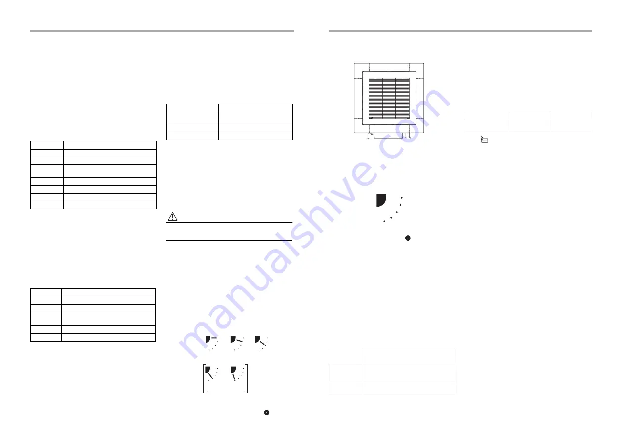
How to set up swing type
The swing type of the louver can be selected.
Follow to the basic operation procedure
(
1
→
2
→
3
→
4
→
5
→
6
→
7
).
• Specify
[F0]
for the Code No. in Procedure
4
.
• Select the following data for the set data in
Procedure
5
.
•
About “Dual swing”
“Dual” means that louvers
01
and
03
are directed
and swing in one direction and louvers
02
and
04
are
directed and swing in the opposite direction.
(When louvers
01
and
03
are directed downward,
louvers
02
and
04
are directed horizontally.)
•
About “Cycle swing”
The four louvers swing independently at respective
timings.
CAUTION
CAUTION
Do not set the swing set data to “
0000
”.
(This setting may cause a failure of the louvers.)
How to set up louver lock
(No swing)
A position of the individual louvers (four directions) can
be locked.
Follow to the basic operation procedure
(
1
→
2
→
3
→
4
→
5
→
6
→
7
).
• Specify
[F1], [F2], [F3], or [F4]
for the Code
NO. in Procedure
4
.
• Select the following data for the set data in
Procedure
5
.
* When (4) or (5) is selected, dew drop may occur
during cooling mode.
• When the setting has been determined,
lights up.
Set data
Detection temperature shift value
0000
No shift
0001
+1°C
0002
+2°C
(Factory default)
0003
+3°C
0004
+4°C
0005
+5°C
0006
+6°C
Set data
Filter sign term
0000
None
0001
150 H
0002
2500 H
(Factory default)
0003
5000 H
0004
10000 H
Swing set data
Swing of louvers
0001
Standard swing
(Factory default)
0002
Dual swing
0003
Cycle swing
(1)
0001
(2)
0002
(3)
0003
(5)
0005
(4)
0004
Set data
How to cancel louver lock
Set the wind direction to “
0000
” of the louver lock setup
procedure above.
• When the setting is canceled,
goes out.
Other operations are the same as those in “How
to set up louver lock (No swing)”.
To select horizontal wind
direction
The louver positions at cooling can be changed from
the smudge reducing position to the cold draftless
position.
Follow to the basic operation procedure
(
1
→
2
→
3
→
4
→
5
→
6
→
7
).
• For the Code No. in Procedure
4
, specify
[45]
.
• Select the following data for the set data in
Procedure
5
.
Remote controller sensor
The temperature sensor of the indoor unit senses room
temperature usually. Set the remote controller sensor
to sense the temperature around the remote controller.
Select items following the basic operation procedure
(
1
→
2
→
3
→
4
→
5
→
6
→
7
).
• Specify
[32]
for the Code No. in Procedure
4
.
• Select the following data for the set data in
Procedure
5
.
When
flashes, the remote controller sensor is
defective.
Select the set data [0000] (not in use) or replace the
remote controller.
Group control
In a group control, a remote controller can control up to
maximum 8 or 16 units. (Depending on the outdoor
unit.)
• The wired remote controller only can control a group
control. The wireless remote controller is unavailable
for this control.
• For wiring procedure and wires of the individual line
(Identical refrigerant line) system, refer to
“7. Electrical connection” in this Manual.
• Wiring between indoor units in a group is performed
in the following procedure.
• Connect the indoor units by connecting the remote
controller wires from the remote controller terminal
blocks (A, B) of the indoor unit connected with a
remote controller to the remote controller terminal
blocks (A, B) of the other indoor unit. (Non-polarity)
• For address setup, refer to the Installation Manual
attached to the outdoor unit.
Wind
direction set
data
Wind direction setting
0000
Smudge reducing position
(Air direction to reduce ceiling
contamination) [Factory default]
0002
Cold draftless position
(Air direction to control cold air fall)
04
[F4]
02
[F2]
03
[F3]
01
[F1]
Drain pipe
Refrigerant pipe
0000
Setting data
Set data
0000
0001
Remote controller
sensor
Not in use
(Factory default)
In use
37-EN
38-EN
Summary of Contents for MMU-UP0051MH-E
Page 31: ...EB99840501 ...


