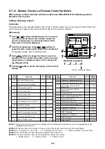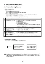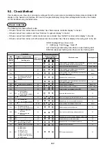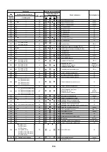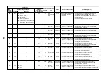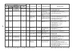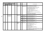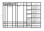
120
New check code
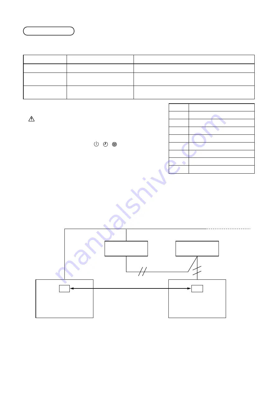
1. Difference between the TCC LINK and AI-NET check code
The displaying method of the check code changes in this model and onwards.
Used characters
Characteristics of code
classification
Block display
AI-NET check code
Hexadecimal notation, 2 digits
Few classification of communication/
incorrect setup system
Indoor P.C. board, Outdoor P.C.
board, Cycle, Communication
TCC Link
Al Decimal notation, 2 digits
Many classification of communication/incorrect setup system
Communication/Incorrect setup (4 ways), Indoor protection,
Outdoor protection, Sensor, Compressor protection, etc.
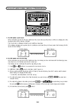
Display in wired remote controller
• [
] is displayed.
• [UNIT No.] + Check code + Operation lamp (Green) flash
Display on sensor part in wireless remote controller
• Block display of combination of [
] [
] [
]
Display on 7-segment in outdoor unit
• Unit No. and check code are displayed.
• In a case of error with auxiliary code, the check code and the
auxiliary code are displayed alternately.
Display
A
C
E
F
H
J
L
P
Classification
Unused
Central control system error
Communication system error
Each sensor error (Failure)
Compressor protective system error
Unused
Setup error, Other errors
Protective device operation
|
|
|
|
|
|
|
|
|
→
2. Special mention
1) If this model is connected to AI-NET by network adaptor, the different check codes are displayed on the
main remote controller and AI-NET central control remote controller.
Example) Indoor TA sensor error
2) The check code of the remote controller is displayed only while the air conditioner is operating (remote
controller start button ON).
When the air conditioner has stopped and the error has been cleared, the check code display on the
remote controller also disappears.
However, if the error continues after the unit has stopped, the check code is immediately displayed when
the unit is restarted.
OC
AI-NET
central control
remote controller
AI-NETWORK BUS
F10
Wired remote controller
Indoorunit
Network adaptor


