85
8-6-2. Cooling/heating test operation check
The cooling/heating test operation check can be performed on both the indoor remote control and the outdoor
header unit interface PC board.
(1) Test operation start/stop operation
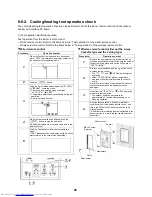
Test operation from the indoor remote control
• Wired remote control: Refer to the items below in “Test operation” of the wired remote control.
• Wireless remote control: Refer to the items below in “Test operation” of the wireless remote control.
▼
Wired remote control
▼
Wireless remote control (Except the 4-way
Cassette type and the Ceiling type)
Procedure
Operation content
1
When the Test button is pushed for 4 seconds or
more, “TEST” is displayed in the display section, and
the unit enters test operating mode.
2
Push the
button.
3
Using the Select Mode button, select the “
COOL”
or “
HEAT” operating mode.
• Do not use an operating mode other than
“
COOL” or “
HEAT”.
• Temperature adjustment is unavailable during test
operation.
• Error is detected as usual.
4
When the test operation has finished, push the
button to stop the operation.
(The same display as in procedure 1 appears in the
display section.)
5
Push the Test button to clear the test operating
mode.
(“TEST” disappears from the display section, and the
status returns to the normal stopped status.)
Procedure
Operation content
1
Remove the nameplate of the receiver section by
inserting a screwdriver or similar tool into the notch at
the bottom of the plate, and set the DIP switch to
“TEST RUN ON.”
2
Execute a test operation with the
button on the
wireless remote control.
• The “
”, “
” and “
” LEDs blink during test
operation.
• Under “TEST RUN ON” status, temperature
adjustment from the wireless remote control is
invalid.
Do not use this method of operation other than for
test operation because the equipment will be
damaged.
3
Use either the “
COOL” or “
HEAT” operation
mode for a test operation.
* The outdoor unit does not operate for
approximately 3 minutes after powering-on or
stopping operation.
4
After the test operation is finished, stop the air
conditioner from the wireless remote control, and
return the DIP switch of the sensor section to its
original position.
(A 60-minute timer clearing function is attached to the
sensor section in order to prevent continuous test
operation.)
M4 × 25 screw
(2 pieces)
Receiver unit
Spacer
Nameplate
Notch
Small screw
Summary of Contents for MMY-MAP0724HT6UL
Page 229: ...228 15Exploded Diagram Parts Price List SMMS i OUTDOOR UNIT MMY MAP0724HT6UL ...
Page 230: ...229 MMY MAP0724HT6UL ...
Page 232: ...231 SMMS i OUTDOOR UNIT MMY MAP0964HT6UL MMY MAP1144HT6UL ...
Page 233: ...232 MMY MAP0964HT6UL MMY MAP1144HT6UL ...
Page 237: ...236 SMMS i INV SERVICE PARTS LIST MMY MAP0724HT6UL 4 pieces PC board ...
Page 238: ...237 SMMS i INV SERVICE PARTS LIST MMY MAP0964HT6UL MMY MAP1144HT6UL 4 pieces PC board ...
Page 241: ...Copyright 2011 TOSHIBA CARRIER CORPORATION ALL Rights Reserved ...


