117
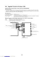
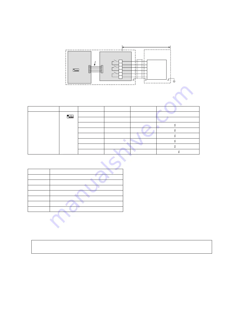
6-8-9. Operating Rate Output
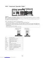
Operation
At the output terminals, a signal is present (relay closed) or absent (relay open) in various combinations according
to the system operation factor, as shown in the diagram.
The operation rate (FA) is the percentage ratio of the current output of the system to the maximum output (100%).
off = Relay open
on = Relay closed
* Connect the optional P.C. board to the header outdoor unit.
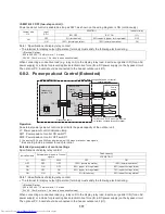
Note 1: Output Relay (K1, K2, K3) Contact Specifications
• Output terminals (OUTPUT1, 2, 3) must satisfy the following electrical rating.
• When connecting a conductive load (e.g. relay coil) to loads K1, K2 and K3, insert a surge killer CR (for an AC
power supply) or a diode for preventing back electromotive force (for a DC power supply) on the bypass circuit.
Function
SW16
OUTPUT1
OUTPUT2
OUTPUT3
Operation factor (FA)
System operation
rate output
Bit 1: ON
Bit 2: OFF
off
off
off
FA=0%
on
off
off
0%
<FA<20%
off
on
off
20% FA
<35%
on
on
off
35% FA
<50%
off
off
on
50% FA
<65%
on
off
on
65% FA
<80%
off
on
on
80% FA
<95%
on
on
on
95% FA
C2
Connection cable 2
CN514
Interface-side connector (green)
MONITOR
Monitoring device
OUTPUT1
Output terminal for each function
OUTPUT2
Output terminal for each function
OUTPUT3
Output terminal for each function
PJ20
Connector on optional PCB side
TB1
Terminal block
<Electrical Rating>
220-240 VAC, 10 mA or more, 1A or less
24 VAC, 10 mA or more, 1 A or less (non-conductive load)
OUTPUT1
CN514
PJ20
OUTPUT2
OUTPUT3
TB1
1
2
5
6
4
3
C2
K1
K2
K3
1 2 3 4
ON
OFF
SW16
MONITOR
Optional PCB
Locally procured
(See “NOTE”)
Header outdoor unit
Outdoor unit
interface PCB
Shield
wire
1
ON
OFF
2 3 4

