243
9-3. Outdoor Unit Backup Operation Setting
<Outline>
This product allows outdoor unit backup operation setting to be performed either at the header unit or a follower
unit. If any of the fault modes specified below occurs to one of the outdoor units in a multi-outdoor unit system,
proceed with outdoor unit backup operation.
• A compressor failure (e.g. a layer short-circuit or a compressor failure in which no compressor is available to
back up the faulty compressor)
• A failure of a pressure sensor (Pd or Ps) or a temperature sensor (TD1, TD2, TD3, TS1, TE1, TE2, TK1, TK2,
TK3, TK4, TK5, or TL)
Note:
Keep the number of backed-up outdoor units to one in the system (single refrigerant line).
9-3-1. Follower outdoor unit backup operation setting
(failure of follower outdoor unit)
<Work procedure>
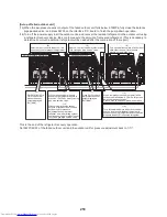
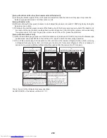
(1) Turn off the power supply to all the indoor and outdoor units connected to the system.
[Setup of failed follower outdoor unit]
(2) Fully close the gas pipe service valve of the failed outdoor unit.
(3) Leave the service valves of the liquid and balance pipe fully open (to prevent refrigerant stagnation in the unit).
However, if there is a leakage from an outdoor PMV (unable to close), fully close the liquid pipe service valve.
(4) <In case of fault in compressor, electrical part, I/F P.C. board, or IPDU P.C. board>
From this point on, keep the power supply to the failed unit off.
<In case of fault in refrigerating circuit or related part (pressure sensor, temperature sensor, refrigerating cycle
part, or fan system part)>
Disconnect the connector [CN03] for outdoor-outdoor communication (BUS2) provided on the interface P.C.
board.
[Setup of header unit]
(5) Turn on Bit 2 of SW09 on the interface P.C. board of the header unit.
(Setting to prevent connected indoor units capacity over error. (E16))
Setup of failed follower outdoor unit
(2)
(3)
(4)
CN03
BUS2
Fully close gas pipe
service valve.
Leave service valves of liquid and balance pipes fully open.
(if there is leakage from outdoor PMV, fully close liquid pipe.)
In case of fault in refrigerating circuit
or related part, disconnect BUS2
communication connector [CN03] on
interface P.C. board.
1
2
3
4
1
2
3
4
1
2
3
4
1
2
3
4
1
2
3
4
1
2
3
4
1
2
3
4
1
2
3
4
SW06
SW07
SW09
SW10
SW11
SW12
1
2
3
4
1
2
3
4
SW16
SW17
SW13
SW14
Interface P.C. board of header unit
(5)
Turn on Bit 2 of SW09.


