91
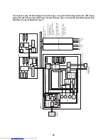
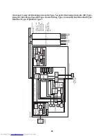
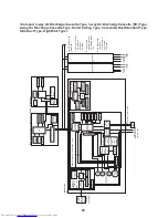
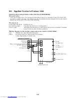
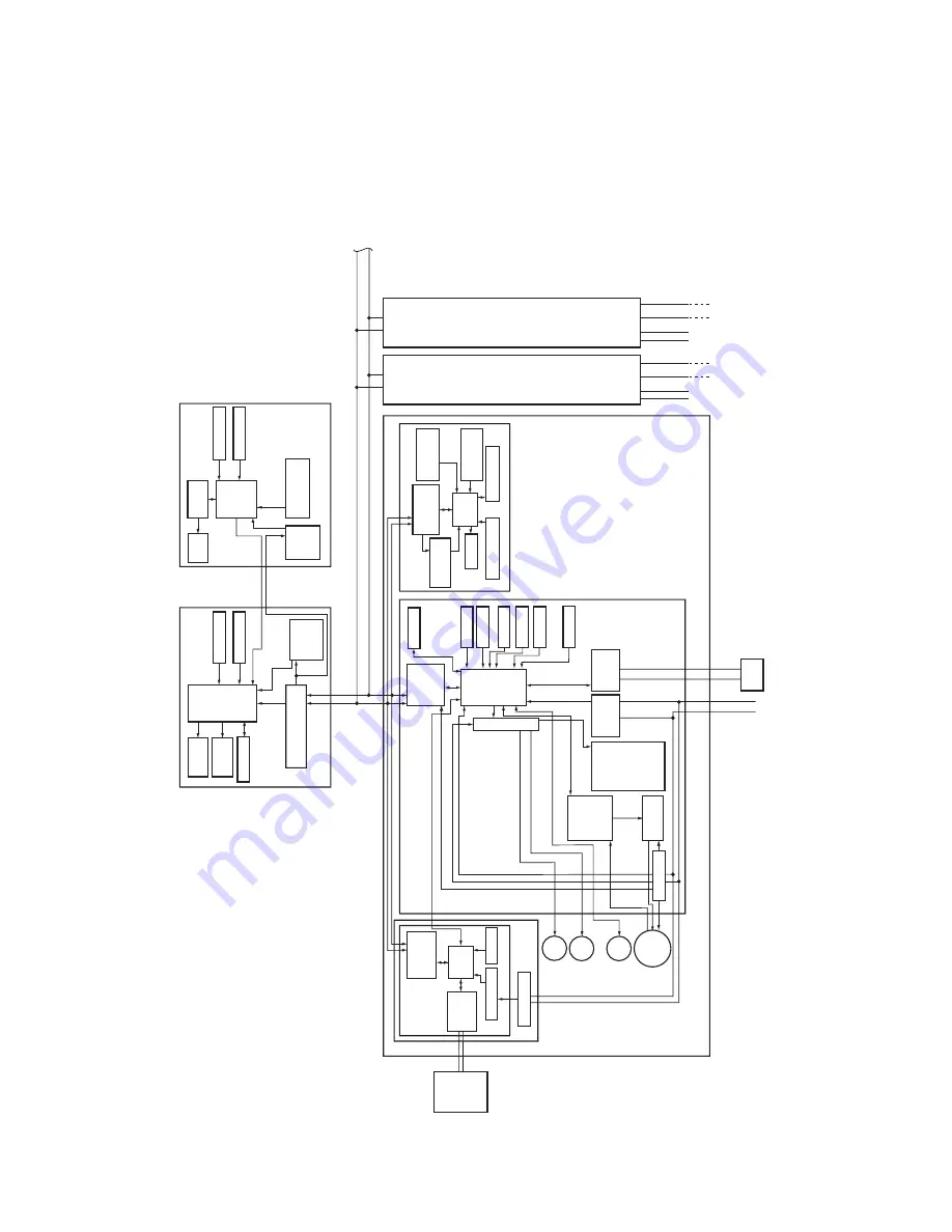
6-1-3. When Both Main (Sub) Remote Controller and Wireless
Remote Controller Kit Connected
<New 4-way Air Discharge Cassette Type> (MMU-AP
2H)
M
C
U
DC 280V
M
C
U
M
C
U
DC5V
DC5V
DC5V
CN2
CN1
DC5V
M
C
U
EEPROM
M
C
U
M
C
U
DC5V
DC12V
DC20V
X
Y
A
B
A
B
A
B
L
N
U
1
U
1
U
2
U
2
HA
R
S
U
1
U
2
R
S
U
1
U
2
EEPROM
W
eekly timer
Main (sub) center remote controller (up to 2 units)
Power
supply
circuit
Function setting
Key switch
Remote controller
communication circuit
Display
LCD
Display
LED
*3
Rechargeable
battery
LCD
driver
Display
LCD
Function setting
Key switch
Power
supply
circuit
Network adaptor (optional)
Indoor unit
Switch setting
Power supply circuit
T
ransformer
Central
control
remote
controller
(optional)
Network
adaptor P
.C.
board
(MCC-1401)
Remote controller
communication
circuit
AI-NET
communication
circuit
#1
(In case of
AI-NETWORK)
Indoor control P
.C. board (MCC-1570)
P
MV
Louver
motor
Drain
pump
Indoor
fan
motor
×4
Power supply circuit
Fan motor
control circuit
T
A
s
e
n
so
r
TCI sensor
TC2 sensor
TCJ sensor
Float input
Driver
R
em
ot
e
controller
co
m
m
un
ic
at
io
n
circuit
* Not applicable to concealed
duct high static pressure type
In operation
Alarm
Getting ready
Thermostat ON
COOL
HEA
T
FAN
AC
syn
chroni
za
tion
sign
al inp
ut ci
rc
uit
BUS
communication
circuit
External
output
Indoor/outdoor communication
Outdoor
unit
Power source
1Ø 220-240V
, 50Hz
1Ø 220V
, 60Hz
Outdoor
unit
Outdoor
unit
Power
source
Power
source
#2
#3
Sameas left
*2
Sameas left
*2
Up to 8 units
can be
connected. *1
*1
Only up to
7 units if a
network
adaptor is
installed.
*2
The
network
adaptor
can only be
installed in
one unit.
*3
A
weekly
timer
cannot be
connected
to a sub
remote
controller
.
Emergency
operation SW
Wireless remote controller kit
Sensor P
.C. board
Power
supply circuit
Remote controller
communication
circuit
Buzzer
Sensor circuit
Display LED
Function
setting SW


