−
29
6
−
5..
T
op plate
1 Detachment
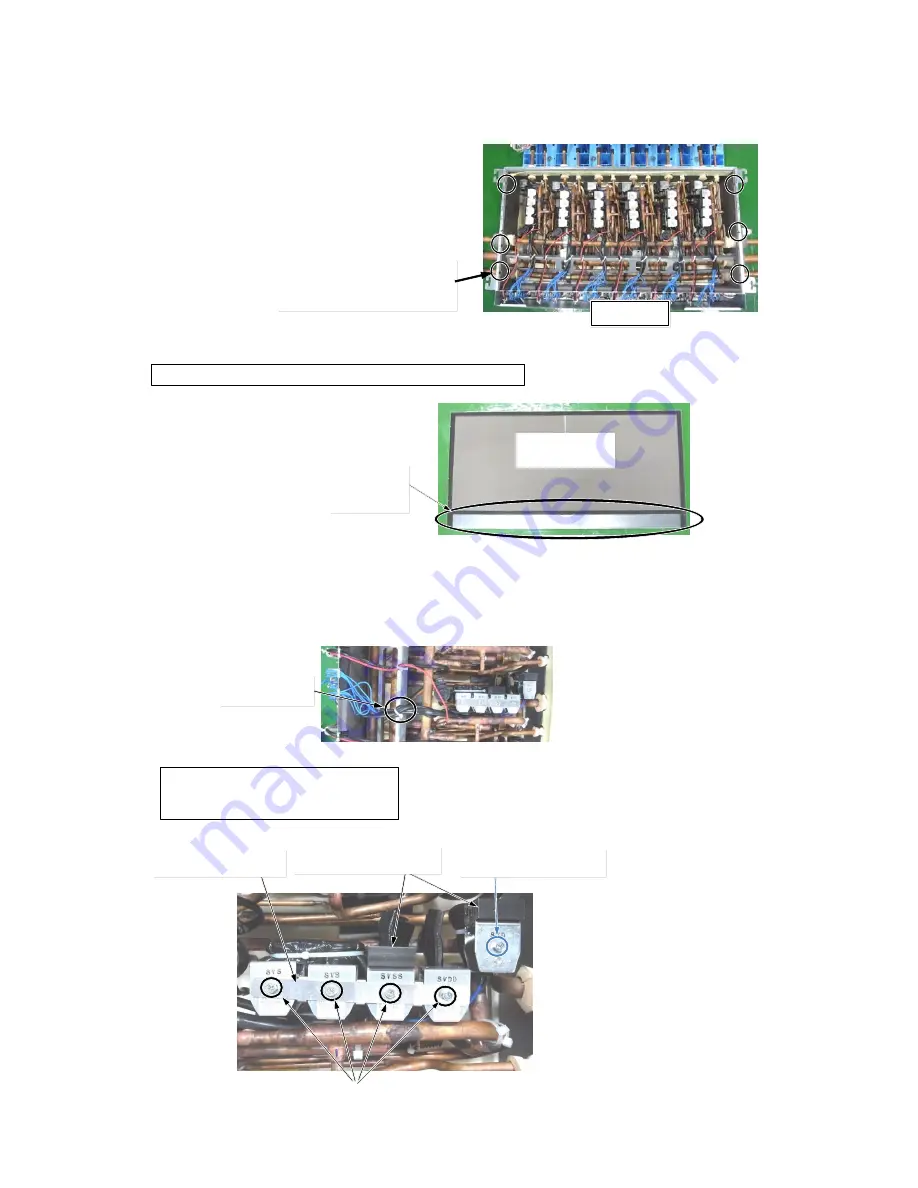
1) Take off the fixing screws (φ4 x 8, 6 pcs)
2) Remove the top plate.
2 Attachment
1) Fix the Top plate as before.
2) Fit the screws. (φ4 x 8, 6 pcs.)
6.. Coil
of
2WAY-VALVE
(SVS, SVSS
,
SVDD, SVD)
1 Detachment
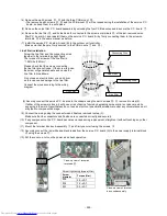
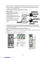
1) Perform work of procedure 1. -1) (Electric parts cover) and 5. -1) (top plate).
2) Cut the binding band (1 pc) for bundling the wires of the coil (SVS, SVSS, SVDD, SVD).
3) Take off the fixing screws, remove the Coil connection plate and then remove the coil.
4) Remove the wires from the terminal (TB01,TB02) and the P.C.board (CN710).
Binding band
Screws (M4x6,4pcs)
Heat sink (SVSS,SVD)
Screw (M4 x 8,1pc)
Coil connection plate
Position of the screw holes
(Top plate)
E-BOX
Non-heat
insulation
The inside of
Fit the non-thermal insulation material side to the E-Box side.
Fixing screw size
SVS, SVSS, SVDD : M4 x 6 (4 pcs)
SVD : M4 x 8 (1 pc)
Summary of Contents for MMY-MAP0806FT7(J)P
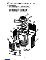
Page 32: ... 31 1 2 Single port FS Unit RBM Y1123FE FE2 RBM Y1803FE FE2 ...
Page 33: ... 32 RBM Y2803FE FE2 ...
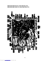
Page 302: ...MMY MAP0806FT8 J P E MAP1006FT8 J P E MMY MAP0806FT8 J P TR MAP1006FT8 J P TR 301 ...
Page 307: ... 306 MMY MAP1206FT8 J P E MAP1406FT8 J P E MMY MAP1206FT8 J P TR MAP1406FT8 J P TR ...


