−
29
7
−
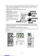
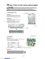
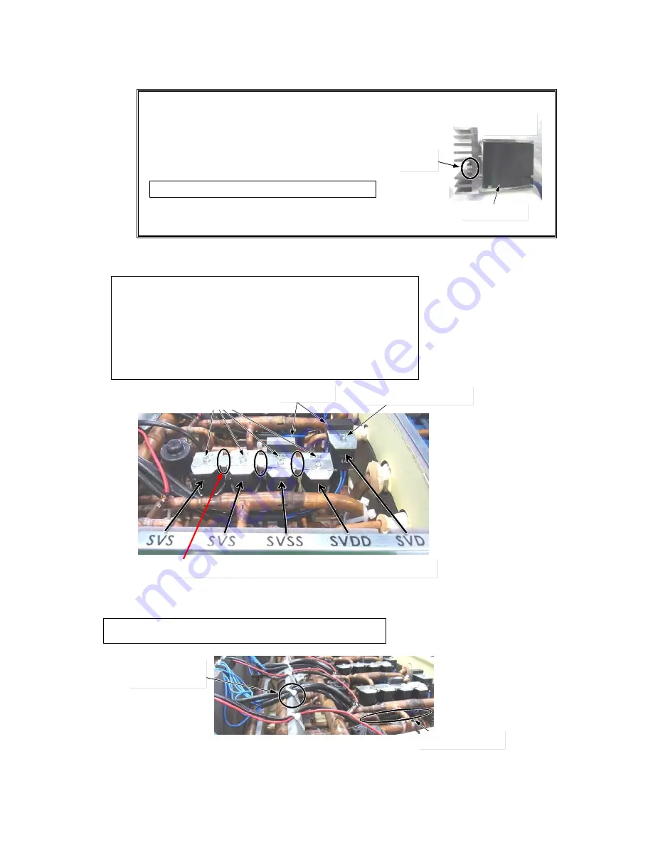
Heat sink
1 Detachment
1) Take off the fixing screws. (M4 x 8, 2 pcs)
2) Remove the heat sink from the coil. (SVSS or SVD)
2 Attachment
1) Fix the heat sink as before.
2) Fit the screws of the heatsink (M4 x 8, 2 pcs)
at a torque of 1.47 ± 0.1 N
・
m.
2 Attachment
1) Fix the coil and the Coil connection plate as before and fit the screws.
3) Connect the wires disconnected as before.
4) Bind the the wires of the coil (SVS, SVSS, SVDD, SVD)
to the reinforcement plate by binding band (field supply) (1 pc).
5) Attach the Electoric parts cover and the Top plate. (Refer to 1. -2) and 5. -2))
Upper side
Screws
SVSS or SVD
For the coil connecting plate, attach the flange downward.
Screw (M4 x 8,1 pc)
Screws
(M4 x 6, 4
pcs)
Heat sink
Binding band
(field supply)
Wiring position
Fix the heatsink to the direction indicated in the figure.
Attach the coil to the position indicated in the coil attachment nameplate.
Be careful about the attachment directions of the coil and Coil connection plate.
Fixing screw size
SVS, SVSS, SVDD : M4 x 6 (4 pcs)
SVD : M4 x 8 (1 pc)
Be careful of using the different screw.
Control tightening torque of the coil with 2.0
±
0.1 N
・
m .
Wire the lead through the lower side than the coil so that the edge
of the coil do not damage the lead
Summary of Contents for MMY-MAP0806FT7(J)P
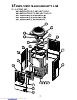
Page 32: ... 31 1 2 Single port FS Unit RBM Y1123FE FE2 RBM Y1803FE FE2 ...
Page 33: ... 32 RBM Y2803FE FE2 ...
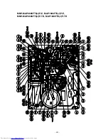
Page 302: ...MMY MAP0806FT8 J P E MAP1006FT8 J P E MMY MAP0806FT8 J P TR MAP1006FT8 J P TR 301 ...
Page 307: ... 306 MMY MAP1206FT8 J P E MAP1406FT8 J P E MMY MAP1206FT8 J P TR MAP1406FT8 J P TR ...


