−
29
8
−
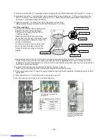
7. Coil-PMV, TCS-sensor
1 Detachment
1)
Perform work of procedure 1. -1) (E
l
ectric parts cover) and 5. -1) (Top plate).
2)
Cut the binding band (1 pc) which fix the Clamp filter to the wires
of the Coil-PMV and the TCS-Sensor.
3)
Remove the Clamp filter from the wires of the Coil-PMV and
TCS-Sensor.
4)
Remove the wires of Coil-PMV from the Wire-clamp.
5)
Remove each wire which is connected from
the control P.C.board to other parts.
6) Cut the binding band (1 pc) of gathering wires of
the Coil-PMV and the TCS-Sensor
and the wires remove from reinforcement plate.
7) Remove the Coil-PMV or the TCS-Sensor.
2 Attachment
1) Fix Coil-PMV or TCS-Sensor assembly as before.
2) Connect the wires disconnected as before.
3) Fix the wire of the PMV-Coil by the Wire-Clamp as before.
4) Fix the Clamp filter by the binding band (field supply) (1 pc)
to the wires of the Coil-PMV and the TCS-Sensor.
5) Fix the wires of Coil-PMV and TCS-Sensor by
the binding band (field supply) (1 pc) to
the reinforcement plate.
6) Attach the Electric parts cover and the Top plate. (Refer to 1. -2) and 5. -2))
CN720
CN101
Binding
band
Wire Clamp
Binding band (field supply)
Clamp Filter
TCS
Sensosr
Push
To fit a pipe
Coil-PMV
Sensor holder
Fix-P-Sens
o
r
Binding band
Binding band
(field supply)
Wire Clamp
TCS-Sensor
Coil-PMV
Clamp Filter
The claw of Coil-PMV should be fitted to the pipe.
Be careful about deformation of the pipe of
connecting PMV.
The TCS-sensor should be inserted deeply into
the sensor holder.
CN720 PMV
White
CN101 TCS Sensor White
Summary of Contents for MMY-MAP0806FT7(J)P
Page 32: ... 31 1 2 Single port FS Unit RBM Y1123FE FE2 RBM Y1803FE FE2 ...
Page 33: ... 32 RBM Y2803FE FE2 ...
Page 302: ...MMY MAP0806FT8 J P E MAP1006FT8 J P E MMY MAP0806FT8 J P TR MAP1006FT8 J P TR 301 ...
Page 307: ... 306 MMY MAP1206FT8 J P E MAP1406FT8 J P E MMY MAP1206FT8 J P TR MAP1406FT8 J P TR ...


