2
14
15
5
7
3
1
4
6
11
9
8
13
12
10
19
1816
20
21
22
17
1 8
3
5
2
9
10
6
7
12
4
11
9
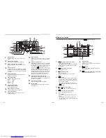
Swing indicator
Displayed during up/down movement of the
louver.
10
Set temperature display
The selected set temperature is displayed.
11
Remote controller sensor indicator
Displayed when the remote controller sensor is
used.
12
Pre-heat indicator
Displayed when the heating mode is energized
or defrost cycle is initiated. While this indication
is displayed, the indoor fan stops or operate in
fan mode.
13
No function indicator
Displayed when the function requested is not
available on that model.
14
Fan speed indicator
Indicates the selected fan speed:
(Auto)
(High)
(Medium)
(Low)
15
Louver Number display
(example:01, 02, 03, 04)
(4-way cassette type only)
16
Power saving mode display
Displayed during power saving mode.
17
Louver lock indicator
Displayed when a louver is locked. (4-way
cassette type only)
1
button (Fan speed select button)
Selects the desired Fan speed.
* Not available for the concealed duct high static
pressure and fresh air intake type. Only “High”
is displayed.
2
button (Timer set button)
Use to setup the timer.
3
button (TEST button)
Use only for service.
(During normal operation, do not use this
button.)
4
button
Use when a ventilator (commercially-available)
is connected. Push the button to turn on/off the
ventilator. Turning on/off the air-conditioner also
turns on/off the ventilator.
* No ventilator is connected if “
” appears on
the remote controller display after pushing the
button.
5
button (Filter reset button)
Resets “ FILTER” indication after cleaning.
6
button (Power save operation)
Use to initiate power saving mode.
7
button
Use to select automatic swing or
fi
xed louver
position.
* Not available for concealed duct, slim duct,
fl
oorconcealed and
fl
oor standing cabinet fresh
air intake types.
8
Operation lamp
Lights up during running.
Blinks when an error occurs or the protective
device activates.
9
button
Turns on the unit when pushed, and turns off
when pushed again.
10
button (Operation mode select button)
Selects desired operation mode.
18
UNIT No. display
Displays the number of the indoor unit selected.
Also displays error code of indoor and outdoor
units.
19
Central control indicator
Displayed when the air conditioner is controlled
centrally and used with central control devices
such as the central remote controller. If the use
of the remote controller is prohibited by the
central control,
blinks when the ON/ OFF,
MODE, or TEMP. button on the remote controller
is pushed, and the buttons do not function.
(Settings that can be con
fi
gured on the remote
controller differ depending on the mode of the
central control. For details, read the Owner’s
Manual of the central remote controller.)
20
Operation mode controlled indicator
Displayed when MODE button is pushed while
operation mode is
fi
xed to cool or heat by the air
conditioner administrator.
21
Operation ready display
This display appears on some models.
22
Service display
Displayed while the protective device works or
an error occurs.
■
Operation section
Once the settings have been con
fi
gured, all you need to do is push the
button from then on.
– 10 –
19-EN
20-EN


