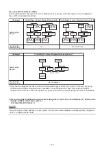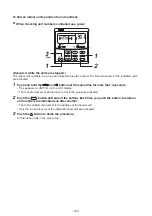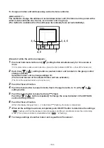
Resetting the address
(Resetting to the factory default (address undecided))
Method 1
Clearing each address separately using a wired remote controller.
Set the system address, indoor unit address and group address to “00Un” using a wired remote controller.
(For the setting procedure, refer to the address setting procedures using the wired remote controller on the
previous pages.)
Method 2
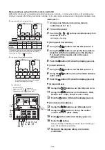
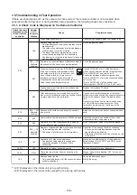
Clearing all the indoor unit addresses on a refrigerate line at once from the outdoor unit.
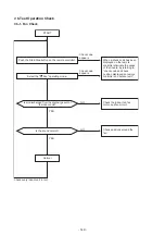
1
Turn off the refrigerant line to reset to the factory default.
2
Turn on the indoor and outdoor units of the refrigerant line for which you want to initialize
the addresses. About one minute after turning on the power, confirm that the 7-segment
display on the header outdoor unit indicates “U.1. - - -” and operate the interface P.C. board
on the header outdoor unit of the refrigerant line as follows.
SW01
SW02
SW03
SW04
Clearable addresses
2
1
2
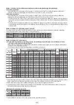
Confirm that the 7-segment display indicates “A.d.buS”
and turn SW04 ON for more than five seconds.
System/indoor unit/group address
2
2
2
Confirm that the 7-segment display indicates “A.d.nEt”
and turn SW04 ON for more than five seconds.
Central control address
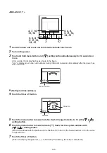
Remote controller
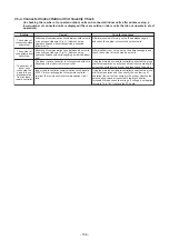
Central control address (I.DN [03]) • Indoor unit address (I.DN [13])
* Address not set will be either "00Un" or "0099", depending on the type of the remote controller.
Communication Type
TU2C-LINK
TCC-LINK
TCC-LINK
Unfixed
00Un
00Un
0099
Display order
• • •
⇔
0128
⇔
00Un
⇔
0001
⇔
• • •
• • •
⇔
0064
⇔
00Un
⇔
0001
⇔
• • •
• • •
⇔
0064
⇔
0099
⇔
0001
⇔
• • •
U series
Other than U series
Remote controller
Line address (I.DN [12])
Communication Type
TU2C-LINK
TCC-LINK
TCC-LINK
Unfixed
00Un
00Un
0099
Display order
• • •
⇔
0128
⇔
00Un
⇔
0001
⇔
• • •
• • •
⇔
0030
⇔
00Un
⇔
0001
⇔
• • •
• • •
⇔
0030
⇔
0099
⇔
0001
⇔
• • •
U series
Other than U series
Remote controller
Group address (I.DN [14])
Communication Type
TU2C-LINK
TCC-LINK
TCC-LINK
Unfixed
Display order
U series
00Un
• • •
⇔
0002
⇔
00Un
⇔
0000
⇔
• • •
Other than U series
• • •
⇔
0002
⇔
0099
⇔
0000
⇔
• • •
0099
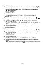
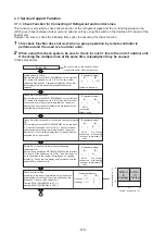
3
Confirm that the 7-segment display indicates “A.d. c.L.” and set SW01, SW02 and SW03 to
1, 1, 1 respectively.
4
After finished clearing the address successfully, “U.1.Err” and “L08 “ appear alternatively at
1 second intervals on the 7-segment display.
5
Set the addresses again after finishing the clearance.
- 131 -
Summary of Contents for MMY-MUP0801HT7JP
Page 309: ......


