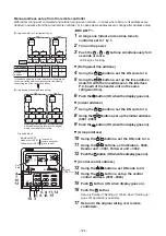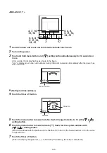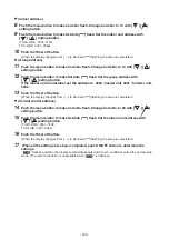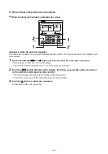
3. Communication method setting
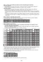
Setup procedure
(1) Turn on indoor units first, and then turn on outdoor units.
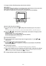
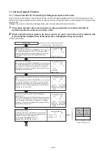
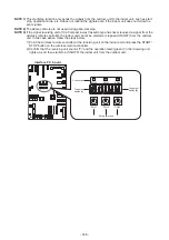
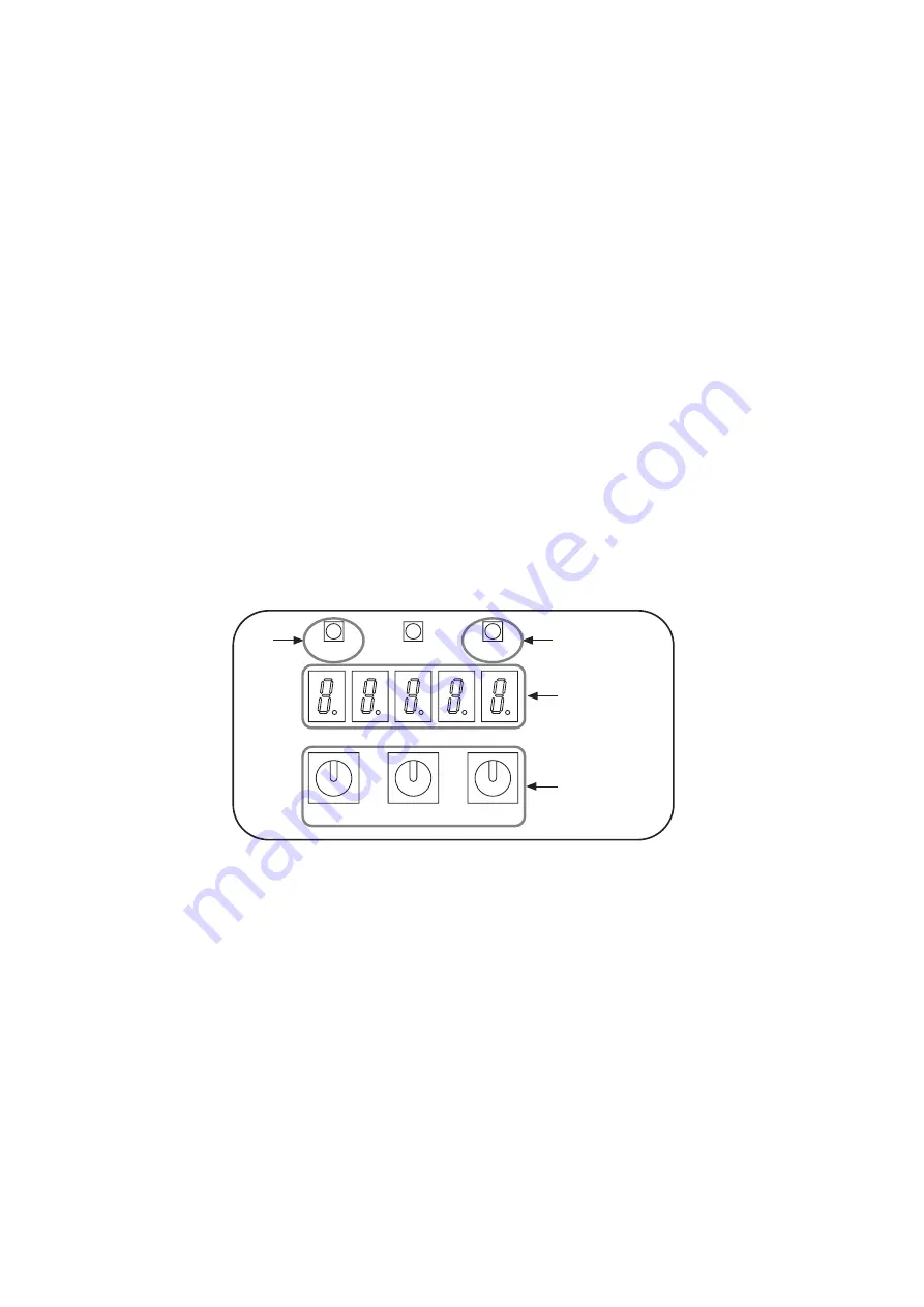
(2) Set the rotary switch of the interface P.C. board on the header outdoor unit to SW01=[2], SW02=[16] and
SW03=[2].
(3) The 7-segment display switches between “c.c. b p s” and “c.c. 0 “ at 1-second intervals.
(4) Push and hold SW04 for more than 5 seconds.
(5) The 7-segment display flashes “c.c.i n”.
(6) The 7-segment display switches between “c.c. i n” and “c.c. *** “ at 1-second intervals.
Check the number of connected indoor units [***].
(When the number of the connected indoor units differs from the number of indoor units displayed on the
7-segment display, clear the communication type setting to eliminate the cause.
To clear the communication type setting, push and hold the SW05 for 5 seconds or more.
The 7-segment display flashes “c.c.r S t”.
After a while, the 7-segment display switches between “c.c. b p s “ and “c.c. 0 “.
Set the rotary switch back to SW01 to [1], SW02 to [1], SW03 to [1].)
(7) Push and hold SW06 for more than 5 seconds.
(8) The 7-segment display flashes “c.c.b p s”.
After that, the setting is complete when the 7-segment display changes to “c.c F i n”.
(If the 7-segment display changes to “c.c. E r r “, try again.)
(9) After a while, the 7-segment display switches between “c.c. b p s “ and “c.c. 1 “ (or “ c.c. o “) at 1-second
intervals.
(10) Set the rotary switch on the interface P.C. board of the header outdoor unit back to SW01=[1], SW02=[1],
SW03=[1].
SW04
SW01
2, 10
SW02
SW03
SW05
Interface P.C. board on the header outdoor unit
SW06
3, 5, 6
8, 9
4
7
- 134 -
Summary of Contents for MMY-MUP0801HT7JP
Page 309: ......


