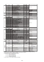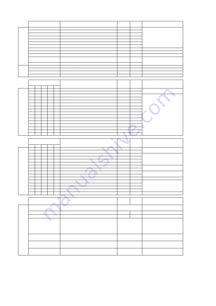
Display
format
Unit
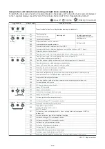
00
Room temperature (Use to control)
X1
°C
01
C
°
1
X
)
r
e
ll
o
r
t
n
o
c
e
t
o
m
e
R
(
e
r
u
t
a
r
e
p
m
e
t
m
o
o
R
02
C
°
4
2
=
]
4
2
0
0
[
C
°
1
X
)
A
T
(
e
r
u
t
a
r
e
p
m
e
t
r
i
a
n
o
i
t
c
u
s
r
o
o
d
n
I
03
C
°
1
X
)
J
C
T
(
e
r
u
t
a
r
e
p
m
e
t
li
o
c
r
o
o
d
n
I
04
C
°
1
X
)
2
C
T
(
e
r
u
t
a
r
e
p
m
e
t
li
o
c
r
o
o
d
n
I
05
C
°
1
X
)
1
C
T
(
e
r
u
t
a
r
e
p
m
e
t
li
o
c
r
o
o
d
n
I
06
Indoor discharge air temperature (TF) *1
X1
°C
07
Indoor fan motor number of revolutions
X10
rpm
[0100]=1000rpm
08
s
l
p
0
0
5
1
=
]
0
5
1
0
[
s
l
p
0
1
/
1
X
g
n
i
n
e
p
o
V
M
P
r
o
o
d
n
I
F3
h
0
0
5
2
=
]
0
0
5
2
[
h
1
X
e
m
i
t
n
g
i
s
r
e
t
li
F
F9
X1
°C
[0024]=24°C
FA
C
°
1
X
1
*
)
A
O
T
(
e
r
u
t
a
r
e
p
m
e
t
r
i
a
e
d
i
s
t
u
O
0A
No. of connected indoor units
X1
units
[0048]=48 units
0B
Total horsepower of connected indoor units
X10
HP
[0415]=41.5HP
0C
s
t
i
n
u
3
=
]
3
0
0
0
[
s
t
i
n
u
1
X
s
t
i
n
u
r
o
o
d
t
u
o
d
e
t
c
e
n
n
o
c
f
o
.
o
N
0D
X
s
t
i
n
u
r
o
o
d
t
u
o
f
o
r
e
w
o
p
e
s
r
o
h
l
a
t
o
T
䋱
0
HP
[0420]=42HP
Display
format
U1
U2
U3
U4
U5
10
20
30
40
50
High-pressure sensor detection pressure(Pd)
X100
Mpa
11
21
31
41
51
Low-pressure sensor detection pressure (Ps)
X100
Mpa
12
22
32
42
52
Compressor 1 discharge temperature (TD1)
X1
°C
13
23
33
43
53
Compressor 2 discharge temperature (TD2)
X1
°C
14
24
34
44
54
C
°
1
X
)
1
S
T
(
e
r
u
t
a
r
e
p
m
e
t
n
o
i
t
c
u
S
15
25
35
45
55
C
°
1
X
)
3
S
T
(
e
r
u
t
a
r
e
p
m
e
t
n
o
i
t
c
u
S
16
26
36
46
56
Outdoor heat exchanger temperature (TE1)
X1
°C
17
27
37
47
57
Outdoor sub-heat exchanger temperature (TE2)
X1
°C
18
28
38
48
58
Outdoor sub-heat exchanger temperature (TE3)
X1
°C
[0024]=24°C
19
29
39
49
59
C
°
1
X
)
O
T
(
e
r
u
t
a
r
e
p
m
e
t
t
n
e
i
b
m
a
e
d
i
s
t
u
O
1A
2A
3A
4A
5A
C
°
1
X
)
1
L
T
(
e
d
i
s
d
i
u
q
il
t
a
e
r
u
t
a
r
e
p
m
e
T
1B
2B
3B
4B
5B
C
°
1
X
)
2
S
T
(
e
r
u
t
a
r
e
p
m
e
t
n
o
i
t
c
u
S
1C
2C
3C
4C
5C
C
°
1
X
)
3
S
T
(
e
r
u
t
a
r
e
p
m
e
t
n
o
i
t
c
u
S
1D
2D
3D
4D
5D
C
°
1
X
)
1
G
T
(
e
r
u
t
a
r
e
p
m
e
t
li
o
c
r
o
o
d
t
u
O
1E
2E
3E
4E
5E
C
°
1
X
)
2
G
T
(
e
r
u
t
a
r
e
p
m
e
t
li
o
c
r
o
o
d
t
u
O
1F
2F
3F
4F
5F
C
°
1
X
)
3
G
T
(
e
r
u
t
a
r
e
p
m
e
t
li
o
c
r
o
o
d
t
u
O
Display
format
U1
U2
U3
U4
U5
60
70
80
90
A0
Compressor oil temperature 1 (TK1)
X1
°C
[0024]=24°C
61
71
81
91
A1
C
°
1
X
)
2
K
T
(
2
e
r
u
t
a
r
e
p
m
e
t
li
o
r
o
s
s
e
r
p
m
o
C
62
72
82
92
A2
s
l
p
1
X
g
n
i
n
e
p
o
1
V
M
P
63
73
83
93
A3
s
l
p
0
0
5
=
]
0
0
5
0
[
s
l
p
1
X
g
n
i
n
e
p
o
2
V
M
P
64
74
84
94
A4
s
l
p
1
X
g
n
i
n
e
p
o
3
V
M
P
65
75
85
95
A5
s
l
p
1
X
g
n
i
n
e
p
o
4
V
M
P
66
76
86
96
A6
A
0
1
X
)
1
I
(
t
n
e
r
r
u
c
1
r
o
s
s
e
r
p
m
o
C
67
77
87
97
A7
A
0
1
X
)
2
I
(
t
n
e
r
r
u
c
2
r
o
s
s
e
r
p
m
o
C
68
78
88
98
A8
s
p
r
0
1
X
s
n
o
i
t
u
l
o
v
e
r
1
r
o
s
s
e
r
p
m
o
C
69
79
89
99
A9
s
p
r
0
1
X
s
n
o
i
t
u
l
o
v
e
r
2
r
o
s
s
e
r
p
m
o
C
6A
7A
8A
9A
AA
e
d
o
m
8
5
=
]
8
5
0
0
[
e
d
o
m
1
X
e
d
o
m
n
a
f
r
o
o
d
t
u
O
6B
7B
8B
9B
AB
Inverter of Compressor 1 heat sink temperature (TH1)
X1
°C
6C
7C
8C
9C
AC
Inverter of Compressor 2 heat sink temperature (TH2)
X1
°C
[0024]=24°C
6D
7D
8D
9D
AD
Inverter of outdoor fan 1 heat sink temperature (TH Fan1)
6E
7E
8E
9E
AE
Inverter of outdoor fan 2 heat sink temperature (TH Fan2)
X1
X1
°C
°C
6F
7F
8F
9F
AF
P
H
6
1
=
]
6
1
0
0
[
P
H
1
X
r
e
w
o
p
e
s
r
o
h
t
i
n
u
r
o
o
d
t
u
O
Display
format
Unit
[0010]=Heating recovery control
1 : Recovery controlled [0001]=Cooling recovery control
W
0
0
9
=
]
0
9
0
0
[
W
0
1
/
1
X
r
e
w
o
p
c
i
r
t
c
e
l
e
s
u
o
e
n
a
t
n
a
t
s
n
I
h
W
0
0
0
9
=
]
0
9
0
0
[
h
W
0
0
1
/
1
X
Integrated electric power consumption
9999
: No setting
[0048]=Termination resistance setting
Indoor unit address 48
[9999]=Case where no terminating
resistance is set to any of the
indoor units
1
䌾
: Setting address
0 : TCC-LINK
[0000]=TCC-LINK
1 : TU2C-LINK
[0001]=TU2C-LINK
0 : 9600 bps
[0000]=9600bps
1 : 19200 bps
[0001]=19200bps
0 : Normally
[0000]=Normally
1 : Demand control
[0001]=Demand control
*1 Only a part of indoor unit types is installed with the discharge air temperature sensor. This temperature is not displayed for other types.
*2 When the units are connected to a group, data of the header indoor unit only can be displayed.
*3 The first digit of code No. indicates the outdoor unit number.
*4 The upper digit of code No. -5 indicates the outdoor unit number.
1
䋪
, 6
䋪
... U1 outdoor unit (Header unit)
2
䋪
, 7
䋪
... U2 outdoor unit (Follower unit 1)
3
䋪
, 8
䋪
... U3 outdoor unit (Follower unit 2)
4
䋪
, 9
䋪
... U4 outdoor unit (Follower unit 3)
5
䋪
, A
䋪
... U5 outdoor unit (Follower unit 4)
*5 Only the Code No. "B
䋪
" of U1 outdoor unit (Header unit) is displayed.
Communications protocol
Uv line communication speed
Demand control
[0642]=64.2rps
[0135]=13.5A
0 : Normal
Termination resistance setting indoor unit address
display
Code No.
Code No.
B0
B5
B6
e
l
p
m
a
x
e
y
a
l
p
s
i
d
r
e
l
l
o
r
t
n
o
c
e
t
o
m
e
R
e
m
a
n
a
t
a
D
Heating/cooling recovery control
e
l
p
m
a
x
e
y
a
l
p
s
i
d
r
e
l
l
o
r
t
n
o
c
e
t
o
m
e
R
e
m
a
n
a
t
a
D
Suction exchanger (TSA) *1
temperature of air to air heat
e
l
p
m
a
x
e
y
a
l
p
s
i
d
r
e
l
l
o
r
t
n
o
c
e
t
o
m
e
R
e
m
a
n
a
t
a
D
Unit
[0123]=1.23MPa
e
l
p
m
a
x
e
y
a
l
p
s
i
d
r
e
l
l
o
r
t
n
o
c
e
t
o
m
e
R
t
i
n
U
e
m
a
n
a
t
a
D
BA
BB
In
d
o
o
r u
n
it
d
a
ta
*2
S
yst
em
d
a
ta
O
ut
door
uni
t i
ndi
vi
dual
dat
a 1 *3
O
ut
door
uni
t i
ndi
vi
dual
dat
a 2 *4
O
ut
door
uni
t
indi
vi
dual
dat
a 3 *5
Code No.
Code No.
B8
B9
- 166 -
Summary of Contents for MMY-MUP0801HT7JP
Page 309: ......

