No.
Part
Work procedure
Remarks
Compressor
(continued)
2. Attachment
1) Carry out installation by following reverse procedure in
the detachment 1) to 4).
2) Install the compressor and braze the pipes, and then
install each wire around the compressor.
(Comp.lead, Case heater, Temperature sensor (TD, TK))
Exchange a comp. leads together as replacing a
compressors.
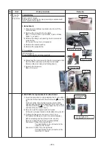
* The right fig. 1 shows caution when the comp. leads
are installed.
• Incorporate the terminal block into the compressor.
• Bend each terminal at 90°while holding the terminal
block so that it does not tilt.
• To prevent the screws from being slanted, place the
comp.leads in the specified position as shown in the
figure, and then tighten the screw according to the
following steps.
(1) Temporary tightening the screws by your hand.
(2) Tighten the screws securely with an electric
screwdriver.
(3) Tighten them with the specified torque using a
torque wrench driver. (2.5N•m)
* Do not screw the screws slantingly.
Otherwise, the comp.leads may burn.
• Insert the comp.leads into the sealing material, and
attach the terminal cover so that they do not pinch
with the terminal cover, and then draw out the
comp.leads straightly.
• Do not apply excessive stress to the comp.leads.
• Do not put the protective tubes in the terminal cover.
• Note that the leads do not touch the comp. shell.
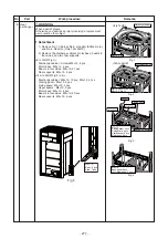
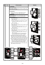
3) Wrap the soundproof material*1 around the
compressor and install the compressor cover *2.
(Fig. 17 to 19)
*1 Wrap the soundproof material around the compressor
so that its bottom is put on the legs of the compressor.
*2 Install the commpressor cover so that pipes or wires
around the comp. do not deform or are caught with the
cover.
6
Black
White
Red
Draw out the comp.
leads straight.
<8 to 14HP>
<
1
4A
to 20HP>
<22 to 24HP>
Fig. 17
Fig. 18
Fig. 19
(soundproof material)
Wrap it clockwise.
(soundproof material)
Wrap it counterclockwise
(soundproof material)
Wrap it clockwise
Three legs
Four legs
Three legs × 2 units
[When attaching two compressors
for 22, 24 HP]
Be sure to wire the comp. lead to the
specified compressors.
Compressor 1: Wire the longer lead to
the left compressor.
Compressor 2: Wire the shorter lead to
the right compressor.
- 281 -
Summary of Contents for MMY-MUP0801HT7JP
Page 309: ......


