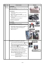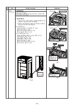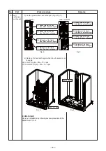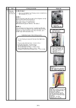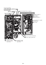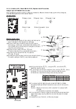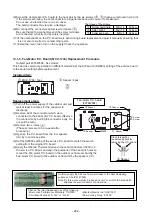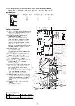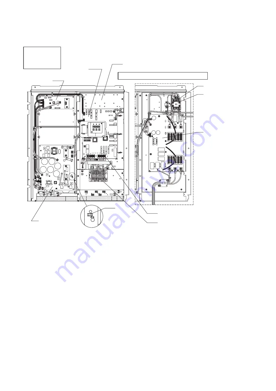
13-1-2. Configuration of inverter assembly
%0
6
.
⊕
㤥
⿒
%0
%0
%0
.
.
%0
%
%
&
%
%
&
⿒
%0
⊕
%0
㤥
%0
%0
%0
.
.
0
8
#
OO
,
:1
%3%
.
2
%0
+%
%0
%0
%0
%0
%0
+%
+%
%0
%0
%0
%0
%0
%0
+%
59
%0
%0
%0
%0
%0
%0
+%
%0
4'#%614
%0
6
%
&$
(
(
+%
%
,
,
,
%
%
&
%0
6
%0
%0
6
%0
%0
%0
%0
6
%0
%0
%0
%0
.
59
59
59
59
59
59
10
10
10
59
59
59
10
59
%0
%0
%0
(
.
㨏
㨁
㨔
㨁
㨢
㨁
61176&11470+6
5*+'.&
5*+'.&
61%'064#.%10641..'4
61+0&11470+6
'*
01219'4
81.6#)'
5722.;
59
MMY-MUP0801*
MMY-MUP1001*
MMY-MUP1201*
MMY-MUP1401*
Inverter P.C. board for fan
(MCC-1734)
Interface P.C. board
(MCC-1747)
The Interface P.C. board sub-assembly
Thermistor
Magnet Contactor
Noise Filter P.C. board(1)
(MCC-1748)
Communication terminal block
Power supply terminal block
Inverter P.C. board
for Compressor(1)
(MCC-1729)
50
Remove the Interface P.C. board sub-assembly
- 286 -
Summary of Contents for MMY-MUP0801HT7JP
Page 309: ......

