


October 2000 © TOSHIBA TEC
5 - 1
MR-2012 CIRCUIT DESCRIPTION
5. CIRCUIT DESCRIPTION
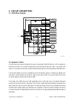
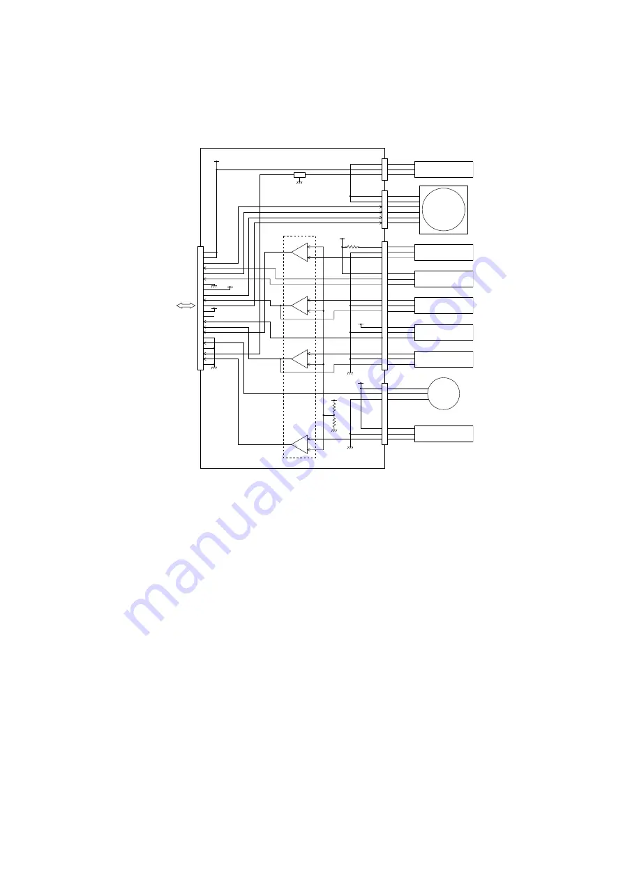
5.1 PWA Block Diagram
5.2 Detection Circuit
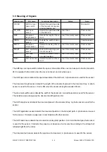
The ADF top cover open switch detects the open or close state of the ADF top cover. 24V is supplied to
the motor when the cover is closed, and switches to the transistor Q1 side when open. The output of Q1
turns to “Low” level when the cover is open and the detection signal is sent to the scanner PWA from CN1.
The document width sensor uses a variable resistor for its detection element. It divides the voltage of 5V
through the variable resistor and sends the output to the scanner PWA. The scanner PWA A-D converts
the input voltage to calculate the document width.
The outputs of the ADF exit sensor, ADF registration sensor, ADF open sensor, and document length
sensor each are input to the IC1 comparator. The reference voltage obtained by dividing 5V though R2 and
R4 is input to the other input of the comparator. The detection level of each sensor is stabilized according
to this reference voltage value and output from the comparator. Since the document empty sensor does
not require accuracy for detecting the presence of a document, its output signal simply passes through the
ADF PWA.
ADF PWA
21
22
1
2
3
4
5
6
7
8
9
10
11
12
13
14
15
16
17
18
19
20
HAISI
1
2
3
ADF
top cover open switch
ADF exit sensor
4
5
6
ADF read sensor
REG+5V
7
8
9
ADF registration sensor
10
11
12
Document empty sensor
OPN+5V
13
14
15
ADF open sensor
Document length sensor
+24V
SG
MOT+24V
COVER
1
2
3
1
2
3
4
5
SIZE
6
Document
width
sensor
ADF motor
CN1
Relay PWA
1
2
3
4
5
6
CN3
CN4
CN5
Q1
CN2
P+5V
NC
SIZE
HAISI
WIDTH
COVER
DF-OPN
EMPTY
/B
REGST
B
/A
D/A
POS
A
+5V
+5V
+5V
+5V
P+5V
+24V
PG
SG
SG
SG
SG
R4
R2
IC1
8
9
6
7
1
-
+
14
-
+
10
11
13
-
+
4
5
2
-
+
ADF 05-01-01


