


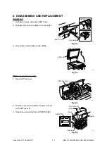


October 2000 © TOSHIBA TEC
5 - 3
MR-2012 CIRCUIT DESCRIPTION
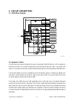
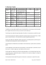
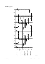
5.4 ADF Motor Drive Circuit
The ADF motor operates according to the driving signals from the scanner PWA. The signals only pass
through the ADF PWA. Therefore, this section describes the ADF motor drive circuit on the scanner PWA.
The ADF motor is driven by amplifying the pulse motor driving pattern signals output from the gate array
through the IC10 motor driver. These signals control the motor rotational direction and speed. The PWM
signal is input to APWM and converted to a certain voltage through the resistor and capacitor. The voltage
is input to IC10 (pins 3 and 14) to set the current value for the motor.
The current value for the motor can be set as desired by changing the duty of the PWM signal. AENB is a
signal to control the output of the motor driver. When the signal is at “High” level, the output of the driver
becomes effective.
IC1
Scanner MPU
IC4
Motor
control IC
IC10
Motor driver
+24V
ADF motor
A
/A
B
/B
CN6
CN1
CN2
CN3
APWM
R8
R7
R6
SG
PG
SG
SG
R5
C6
C7
CPU
A0~19
CPUD0~15
75
AENB
72
ADTB
78
ADTA
77
ASTB
74
ACKO
76
17
6
2,13
5,16
A
1
3
1,2
/A
8
4
B
11
5
/B
18
R3,R4
9
R1,R2
10
6
3
1,2
4
5
6
3
1,2
2
1
5
9
11
+5V
2
5
1
Q1
3
14
Scanner control PWA
ADF PWA
ADF top cover open switch
ADF 05-04-01


