4.3 Wiring
Unified Controller nv-pack series TC-net I/O Loop PCI Express Card JTLI41 Instruction Manual
23
4.3 Wiring
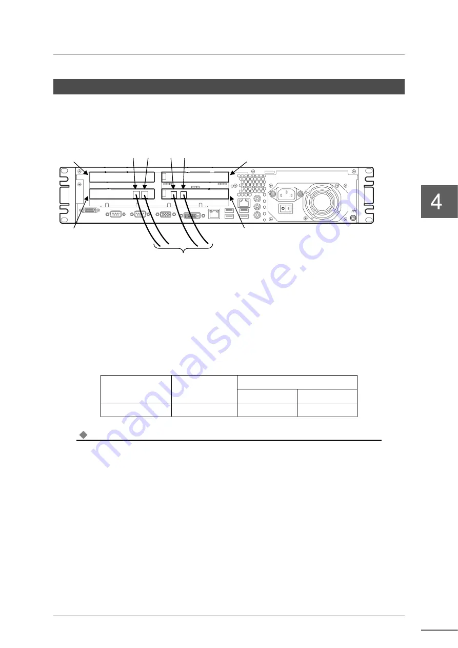
On the front panel of the card, there are TC-net I / O loop connectors (LP1 and LP2).
Wire the transmission cable to LP1 and LP2 as shown below.
Figure 4-9 Appearance and wiring during card mounting
Clamping cables
After connecting the cables, clamp them so that the weight and bending force of the cables will not
directly affect the connectors. Table 4-1 shows the allowable bending radius of the cables for
laying and fixation. Make sure that the cable bends are not smaller than these radii.
Table 4-1 Allowable Cable Bending Radius
Cable External
Diameter (mm)
Allowable Bending Radius
Clamped Connected
Optical fiber cable
5mm
50mm
50mm
Note
The allowable bending radius depends on the optical fiber cable product. Follow the bending radius
of the optical fiber cable specified by the manufacturer.
Optial fiber cable
LP1
LP2
LP2
LP1
Slot 51
Slot 50
Slot 52
Slot 53
Summary of Contents for nv-pack JTLI41
Page 14: ...6F8C1601 xii ...
Page 18: ...Chapter 1 Overview 6F8C1601 4 ...
Page 22: ...Chapter 2 Names and Functions of Parts 6F8C1601 8 ...
Page 30: ...Chapter 3 Settings 6F8C1601 16 ...
Page 44: ...Chapter 5 Maintenance and Inspection 6F8C1601 30 ...
Page 49: ...35 Appendix B Outside Dimensions B 1 JTLI41 36 ...
Page 51: ...37 Appendix C Related Products ...
Page 53: ...39 Appendix D Decimal Hex Conversion Table ...
Page 56: ...Appendix D Decimal Hex Conversion Table 6F8C1601 42 ...
Page 58: ...1601 1 1703 ...


