background image


Portégé 3500 

User's Manual 

Portégé 3500

 Version 

1

 Last Saved on 17.10.2002 16:26 


3500


Portable Personal Computer 
User’s Manual 
 

Summary of Contents for Portege 3500

Page 1: ...Portégé 3500 User s Manual i 3500 Portable Personal Computer User s Manual ...

Page 2: ...ect to change without notice TOSHIBA assumes no liability for damages incurred directly or indirectly from errors omissions or discrepancies between the computer and the manual 8VEHIQEVOW Intel and Pentium are registered trademarks and SpeedStep is a trademark of Intel Corporation Windows and Microsoft are registered trademarks of Microsoft Corporation Photo CD is a trademark of Eastman Kodak Blue...

Page 3: ...the following networks It has been tested to and found to conform with the additional requirements conditional in EG 201 121 Germany ATAAB AN005 AN006 AN007 AN009 AN010 and DE03 04 05 08 09 12 14 17 Greece ATAAB AN005 AN006 and GR01 02 03 04 Portugal ATAAB AN001 005 006 007 011 and P03 04 08 10 Spain ATAAB AN005 007 012 and ES01 Switzerland ATAAB AN002 All other countries regions ATAAB AN003 004 S...

Page 4: ...e bottom side of the computer becomes hot when operated for a long time If you feel uncomfortable with the heat stop operating the computer and wait for cooling down If you maintain physical contact with the computer for a long time on your lap or in your forearm in tablet mode for example your skin might suffer low temperature injury If the computer has been used for a long time avoid direct cont...

Page 5: ...d standards To avoid in general EMC problems following advice should be observed Only CE marked options should be connected implemented Only best shielded cables should be connected SVOMRK IRZMVSRQIRX This product was designed to fulfil the EMC electromagnetic compatibility requirements to be observed for so called Residential commercial and light industry environments TOSHIBA do not approve the u...

Page 6: ...ission before use of this product Furthermore for general safety reasons the use of this product in environments with explosive atmospheres is not permitted 2IX SVO GSRRIGXMSR GPEWW EVRMRK If this product has networking capabilities and will be connected to a network Class A radiation limits will be observed in accordance with technical conventions This means that if the product will be used in a ...

Page 7: ...2 GEVHW The Wireless LAN Card supports the following wireless LAN features Automatic Transmit Rate Select mechanism in the transmit range of 11 5 5 2 and 1 Mbit s Frequent Channel Selection 2 4 GHz Roaming over multiple channels Card Power Management Wired Equivalent Privacy WEP data encryption based on the 128 bit RC4 encryption algorithm as defined in the IEEE 802 11 standard on wireless LANs MV...

Page 8: ... uncertain of the policy that applies on the use of wireless devices in a specific organisation or environment e g airports you are encouraged to ask for authorisation to use the Wireless LAN device prior to turning on the equipment 7EJIX RWXVYGXMSR JSV MVIPIWW 4VSHYGXW If your computer has wireless function all safety instructions must be read carefully and must be fully understood before attempt...

Page 9: ...owded commuter train Keep this product away from a cardiac pacemaker at least 22cm Radio waves can potentially affect cardiac pacemaker operation thereby causing respiratory troubles Turn OFF the Wireless Communication switch inside a medical facility or near medical electric equipment Do not bring medical electric equipment close to the product Radio waves can potentially affect medical electric ...

Page 10: ...nstructions as described in the user documentation that comes with the product This device complies with the following radio frequency and safety standards EREHE r RHYWXV EREHE This device complies with RSS 210 of Industry Canada Operation is subject to the following two conditions 1 this device may not cause interference and 2 this device must accept any interference including interference that m...

Page 11: ...7 MHz en 11 2462 MHz Voor privé gebruik buiten gebouw over publieke groud over afstand kleiner dan 300m geen registratie bij BIPT IBPT nodig voor gebruik over afstand groter dan 300m is wel registratie bij BIPT IBPT nodig Voor publiek gebruik buiten gebouwen is licentie van BIPT IBPT verplicht Voor registratie of licentie kunt u contact opnemen met BIPT L utilisation en extérieur est autorisé sur ...

Page 12: ...ura da seguire L uso per installazione in esterni non e permessa Nederland License required for outdoor installations Check with reseller for procedure to follow Licentie verplicht voor gebruik met buitenantennes Neem contact op met verkoper voor juiste procedure 97 IHIVEP SQQYRMGEXMSRW SQQMWWMSR This device complies with Part 15 of FCC Rules Operation of the devices in a Wireless LAN System is su...

Page 13: ... the FCC exposure requirements Spacific Absorbtion Rate Refer to the Regulatory Statements as identified in the documentation that comes with those products for additional information 8EM ER Article 14 Unless approved for any model accredited low power radio frequency electric machinery any company trader or user shall not change the frequency increase the power or change the features and function...

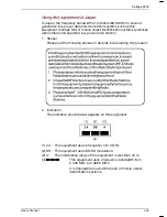
Page 14: ...pecified low power radio station 1 Sticker Please put the following sticker on devices incorporating this product 2 Indication The indication shown below appears on this equipment 1 2 4 This equipment uses a frequency of 2 4 GHz 2 DS This equipment uses DS SS modulation 3 4 The interference range of this equipment is less than 40 m 4 This equipment uses a frequency bandwidth from 2 400 MHz to 2 48...

Page 15: ... data communication system radio station stipulated in the Radio Law and the Telecommunications Business Law of Japan The Name of the radio equipment MPCI3A 20 R JAPAN APPROVALS INSTITUTE FOR TELECOMMUNICATIONS EQUIPMENT Approval Number D01 1128JP TELECOM ENGINEERING CENTER Approval Number 01NY A1088 The following restrictions apply Do not disassemble or modify the device Do not install the embedd...

Page 16: ...ont with the display closed 2 1 Left side 2 3 Right side 2 5 Back side 2 5 Underside 2 7 Front with the display open 2 8 Indicators 2 11 AC adaptor 2 13 Chapter 3 Getting Started 3 1 Setting up your work space 3 2 Opening the display 3 6 Connecting the AC adaptor 3 7 Opening the display 3 8 Turning on the power 3 9 Starting up for the first time 3 10 Turning off the power 3 10 Restarting the compu...

Page 17: ... 26 Chapter 5 The Keyboard 5 1 Typewriter keys 5 1 F1 F12 function keys 5 2 Soft keys Fn key combinations 5 2 Windows special keys 5 6 Keypad overlay 5 6 Generating ASCII characters 5 8 Chapter 6 Power and Power Up Modes 6 1 Power conditions 6 1 Power indicators 6 2 Battery types 6 4 Care and use of the Battery Pack 6 6 Safety precautions 6 7 Replacing the Battery Pack 6 14 Starting the computer b...

Page 18: ...rity lock 8 18 Chapter 9 Troubleshooting 9 1 Problem solving process 9 1 Hardware and system checklist 9 3 Appendix A Specifications Appendix B AC Power Cord and Connectors Appendix C The TOSHIBA International Warranty Appendix D Keyboard Layouts Appendix E Display Controller and Modes Appendix F If your computer is stolen Appendix G ASCII Character Codes Appendix H AT Commands Appendix I S regist...

Page 19: ...ntroduction and The Grand Tour chapters to familiarize yourself with the computer s features components and accessory devices Then read Getting Started for step by step instructions on setting up your computer If you are an experienced computer user please continue reading the preface to learn how this manual is organized then become acquainted with this manual by browsing through its pages Be sur...

Page 20: ...n features LAN and internal modem Chapter 5 The Keyboard describes special keyboard functions including the keypad overlay and hotkeys Chapter 6 Power and Power Up Modes gives details on the computer s power resources and battery save modes Chapter 7 HW Setup and Passwords explains how to configure the computer using the HW Setup program It also tells how to set a password Chapter 8 Optional Devic...

Page 21: ...ing their definition For example Read Only Memory ROM Acronyms are also defined in the Glossary GSRW Icons identify ports dials and other parts of your computer The indicator panel also uses icons to identify the components it is providing information on I W The keyboard keys are used in the text to describe many computer operations A distinctive typeface identifies the key top symbols as they app...

Page 22: ...the same time press C If three keys are used hold down the first two and at the same time press the third ABC When procedures require an action such as clicking an icon or entering text the icon s name or the text you are to type in is represented in the type face you see to the left MWTPE ABC Names of windows or icons or text generated by the computer that appears on its display screen is present...

Page 23: ... to your attention Each type of message is identified as shown below Pay attention A caution informs you that improper use of equipment or failure to follow instructions may cause data loss or damage your equipment Please read A note is a hint or advice that helps you make best use of your equipment ...

Page 24: ...einstalled by TOSHIBA UYMTQIRX GLIGOPMWX Carefully unpack your computer Save the box and packing materials for future use Check to make sure you have all the following items PORTÉGÉ 3500 Portable Personal Computer Universal AC Adaptor and power cord TOSHIBA tablet pen hereafter the tablet pen The tablet pen is included in the carton of pen set with the product when purchased Spare pen tip and draw...

Page 25: ...less LAN Driver Software Modem Driver SD card Driver Utilities Hotkey Utility for Display Devices Power Saver Common Modules Console Network Device Switch Skins for Windows Media Player Online manual Sensiva Symbol CommanderTM Documentation PORTÉGÉ 3500 Portable Personal Computer User s Manual PORTÉGÉ 3500 Quickstart Safety Instruction Manual Warranty Information Product Recovery Disk Tools Utilit...

Page 26: ...ssors may be introduced in the future 1IQSV Built in SDR memory modules are available in 128 or 256 or 512 MB Memory modules can be installed in the two memory slots for a maximum of 1 GB system memory Expansion slot The computer has two slots for Random Access Memory RAM cards System memory up to 1 GB can be installed Level 2 cache A 512 KB level 2 cache is provided to maximize performance Video ...

Page 27: ...ric overlay dedicated cursor control and keys 8SYGL TEH Built in A touch pad and control buttons in the palm rest enable control of the on screen pointer and scrolling of windows 837 XEFPIX TIR Supplied A pen enables data entry directly through the display screen 4S IV Battery Pack The computer is powered by one rechargeable lithium ion polymer Battery Pack RTC battery The internal RTC battery bac...

Page 28: ... enables data transfer speeds 40 times faster than USB 1 1 standard The ports also support USB 1 1 7PSXW PC card The PC card slot accommodates one 5 mm Type II card SD card This slot lets you easily transfer data from devices such as digital cameras and Personal Digital Assistants that use SD card flash memory You can use memory module in this slot Compact Flash module This slot accommodates Compa...

Page 29: ...s 100BASE Tx Wireless LAN In some markets the computer is equipped with a Wireless LAN mini PCI card that is compatible with other LAN systems based on Direct Sequence Spread Spectrum radio technology that complies with the IEEE 802 11 Standard Revision B It supports data transfer up to 11 Mbit s It has Frequency Channel Selection 2 4 GHz and allows roaming over multiple channels This description ...

Page 30: ...er TOSHIBA Utilities A number of utilities and drivers are preinstalled to make your computer more convenient to use Refer to the Utilities section in this chapter Plug and Play When you connect an external device to the computer or when you install a component Plug and Play capability enables the system to recognize the connection and make the necessary configurations automatically ...

Page 31: ...automatic power off This feature automatically cuts off power to the hard disk drive when it is not accessed for a time specified Power is restored when the hard disk is accessed You can specify the time in the Turn off hard disks item of the Power Save Mode window in Power Saver System automatic power off This feature automatically turns off power to the system when there is no input for a time s...

Page 32: ... s main memory When you turn on the power again you can continue working right where you left off Hibernation This feature lets you turn off the power without exiting from your software The contents of main memory is saved to the hard disk when you turn on the power again you can continue working right where you left off Heat dispersal To protect from overheating the CPU has an internal temperatur...

Page 33: ...ay on the internal LCD and on an external computer monitor To enable this function use the Display Properties dialog box Symbol Commander This software enables the user to run an application or to show home page by drawing a simple mark on the display with the TOSHIBA tablet pen You can customize the action to boot the computer and to run the application Sound driver A broad range of audio control...

Page 34: ... easy access to help and services It is the default function launched by the TOSHIBA Console button Bluetooth TOSHIBA stack This software enables communication between remote Bluetooth devices Refer to the Quick Start Guide Bluetooth cannot be used in models that do not have a Bluetooth module installed ...

Page 35: ...odates 1 44 megabyte or 720 kilobyte diskettes It connects to a USB port You cannot format 720 kilobyte diskettes on Windows XP but you can use previously formatted disks Battery Charger The Battery Charger lets you charge extra batteries outside the computer Security lock A slot is available to attach a security cable to the computer to deter theft Wireless LAN Kit This option enables wireless LA...

Page 36: ...operate the computer VSRX MXL XLI HMWTPE GPSWIH The figure below shows the computer s front with its display panel in the closed position Front of the computer with display closed 4SVXÃKÃ 9WIVkW 1ERYEP BATTERY MICROPHONE JACK HEAD PHONE JACK VOLUME CONTROL BATTERY LOCK INDICATOR DISPLAY LATCH BUTTON BATTERY RELEASE LEVER INFRARED PORT POWER SOURCE SYSTEM INDICATORS ...

Page 37: ...f the Battery lock by color The indicator shows red when the Battery lock is released Display latch button The latch mechanism secures the LCD panel in its closed position Push the Display latch button to release the latch to open the display Power source system indicators LEDs let you monitor the status of various computer functions Details are given in the Indicators section Infrared port This i...

Page 38: ...nual 2 3 0IJX WMHI The figure below shows the computer s left side The left side of the computer COMPACT FLASH MODULE SLOT PC CARD SLOT SD CARD SLOT WIRELESS COMMUNICATION SWITCH MODEM JACK WITH COVER OPENED SD CARD INDICATOR ...

Page 39: ...e a modular cable to connect the modem directly to a telephone line The modem is not supported in some marketing regions Do not connect the modem to a digital telephone line A digital line will damage the modem In case of a lightning storm unplug the modem cable from the telephone jack Do not connect the modem to a digital telephone line A digital line will damage the modem Wireless communication ...

Page 40: ...s attached to this slot The optional security cable anchors your computer to a desk or other large object to deter theft EGO WMHI The figure below shows the computer s back side The computer s back side SECURITY LOCK SLOT LAN JACK WITH COVER OPEN FAN VENT DC IN 15V EXTERNAL MONITOR PORT WITH COVER OPEN USB PORTS LAN ACTIVE INDICATOR ORANGE LINK INDICATOR GREEN ...

Page 41: ... Bus ports are on the back side The ports comply with the USB 2 0 standard which enables data transfer speeds 40 times faster than the USB 1 1 standard The ports also support USB 1 1 Keep foreign objects out of the USB connectors A pin or similar object can damage the computer s circuitry LAN jack This jack lets you connect to a LAN The adaptor has built in support for Ethernet LAN 10 megabits per...

Page 42: ...mory module to increase your computer s memory by 256 MB Refer to the Memory expansion section in Chapter 8 Optional Devices Battery Pack The Battery Pack powers the computer when the AC adaptor is not connected The Batteries section in Chapter 6 Power and Power Up Modes describes how to access the Battery Pack Battery Packs can be purchased from your TOSHIBA dealer to extend the computer s batter...

Page 43: ...with the display open POWER BUTTON MICROPHONE SENSOR SWITCH TOUCH PAD TOUCH PAD CONTROL BUTTONS SPEAKER WINDOWS SECURITY TABLET BUTTON ARROW BUTTON 1 ENTER MENU BUTTON 2 FROM LEFT TO RIGHT DISPLAY SCREEN DISPLAY LATCH DISPLAY HINGE POWER BUTTON LOCK TOSHIBA TABLET PEN ...

Page 44: ...used to record monaural sounds into your application Power button A Touch pad located in the centre of the palm rest is used to control the on screen pointer Refer to the Using the Touch pad section in Chapter 4 Operating Basics Power button lock Set this lock to the locked position to prevent inadvertent power on or off Sensor switch This switch shuts down the computer when you close the cover in...

Page 45: ...than a second Arrow button 2 This button functions as the same to key Speaker The speaker emits sound generated by your software as well as audio alarms such as low battery condition generated by the system Display latch The Display latch secures the Display screen in its closed position The latch can be rotated to lock the Display screen in the tablet mode ...

Page 46: ...ange Power The Power indicator glows green when the computer is on If you turn off the computer in Resume mode this indicator blinks orange one second on two seconds off while the computer shuts down Battery The Battery indicator shows the condition of the charge Green means fully charged and orange means being charged Refer to Chapter 6 Power and Power Up Modes Disk The Disk indicator glows in gr...

Page 47: ...Lock indicator When the F10 key indicator glows the keypad overlay lets you control the cursor When the F11 key indicator glows the keypad overlay lets you enter numbers Keypad overlay indicators When the CapsLock indicator glows the keyboard is in all caps mode Caps Lock indicator ARROW MODE NUMERIC MODE CAPS LOCK ...

Page 48: ...ypad overlay section in Chapter 5 The Keyboard EHETXSV The AC adaptor converts AC power to DC power and reduces the voltage supplied to the computer It can automatically adjust to any voltage from 100 to 240 volts and to a frequency of either 50 or 60 hertz enabling you to use the computer in almost any region To recharge the battery simply connect the AC adaptor to a power source and the computer...

Page 49: ...lso to read the Safety Instruction Manual This guide which is included with the computer explains product liability Opening the computer in tablet mode Connecting the AC adaptor Opening the display Turning on the power Starting up for the first time Turning off the power Restarting the computer Restoring the preinstalled software All users should be sure to carefully read the sections Turning on t...

Page 50: ...r stressful work habits can result in discomfort or serious injury from repetitive strain to your hands wrists or other joints Proper ambient conditions should also be maintained for the computer s operation This section discusses the following topics General conditions Placement of the computer and peripheral devices Seating and posture Lighting Work habits ...

Page 51: ...y from heat sources such as electric heaters Do not use the computer near liquids or corrosive chemicals Do not place the computer near objects that create strong magnetic fields e g stereo speakers Do not operate the computer in close proximity to a mobile phone 4PEGIQIRX SJ GSQTYXIV Position the computer and peripheral devices to provide comfort and safety Set the computer on a flat surface at a...

Page 52: ... Adjust the back of your chair so it supports the lower curve of your spine Sit straight so that your knees hips and elbows form approximately 90 degree angles when you work Do not slump forward or lean back too far 0MKLXMRK Proper lighting can improve legibility of the display and reduce eye strain Position the computer so that sunlight or bright indoor lighting does not reflect off the screen Us...

Page 53: ...rcise and stretch your wrists and hands a number of times during the day Frequently look away from the computer and focus your eyes on a distant object for several seconds for example 30 seconds every 15 minutes Take frequent short breaks instead of one or two long breaks for example two or three minutes every half hour Have your eyes examined regularly and visit a doctor promptly if you suspect y...

Page 54: ...the computer when using the computer in tablet mode held in your forearm Do not use the computer while walking or driving a car Change to laptop mode and turn off the computer before carrying Do not carry the computer with power on or in stand by state Do not carry the computer while DISK LED is glowing Do not expose the computer with rapid temperature change such as the case to bring the PC from ...

Page 55: ... way to get started because the Battery Pack will need to be charged before you can operate from battery power The AC adaptor can be connected to any power source supplying from 100 to 240 volts and 50 or 60 hertz For details on using the AC adaptor to charge the Battery Pack refer to Chapter 6 Power and Power Up Modes Use only the AC adaptor that came with the computer or an equivalent optional a...

Page 56: ...he front of the computer should glow 3TIRMRK XLI HMWTPE The display panel can be rotated in a wide range of angles for optimal viewing 1 Push down the display latch on the front of the computer to unlatch the display panel 2 Lift the panel up and adjust it to the best viewing angle for you User reasonable care when opening and closing the display panel Opening it vigorously or slamming it shut cou...

Page 57: ... system Refer to the section Starting up for the first time in this chapter 1 If the external diskette drive is connected make sure it is empty If a diskette is in the drive press the eject button and remove the diskette 2 Open the display panel 3 Slide the power button lock toward the right of the computer to unlock the button then press and hold the button for two or three seconds Turning on the...

Page 58: ...urned off in one of the following modes Shut down Boot Hibernation or Standby mode 7LYX S R QSHI SSX QSHI When you turn off the power in Shut Down mode no data is saved and the computer will boot to the operating system s main screen 1 If you have entered data save it to the hard disk or to a diskette 2 Make sure all disk activity has stopped then remove any CDs or diskette Make sure the Disk is o...

Page 59: ...le while the computer is in hibernation mode Data will be lost IRIJMXW SJ LMFIVREXMSR The hibernation feature provides the following benefits Saves data to the hard disk when the computer automatically shuts down because of a low battery For the computer to shut down in hibernation mode the hibernation feature must be enabled in two places in TOSHIBA Power Saver the Hibernate window and the Batter...

Page 60: ...nter Hibernate mode automatically when you Press the power button Close the lid the Display First however make the appropriate settings according to the steps below 1 Open the Windows Control Panel 2 Open Performance and Maintenance 3 Open TOSHIBA Power Saver 4 Select the Hibernate window select the Enable Hibernate support check box and click the Apply button 5 Select the Power Save Modes window ...

Page 61: ... all other devices are in sleep mode If the computer is not used or accessed in any way including receipt of e mail for 30 minutes when the AC adaptor is connected the computer will automatically enter Standby mode TOSHIBA Power Saver default To restore operation press the power button or press any key The latter action works only if Wake up on Keyboard is enabled in HW Setup If a network applicat...

Page 62: ...can use the panel power off feature IGYXMRK WXERHF You can also enable Standby by pressing Fn F3 See Chapter 5 The Keyboard for details You can enter standby mode in one of three ways 1 Click Start click Turn Off Computer and click Stand by 2 Close the display panel This feature must be enabled To enable it select the TOSHIBA Power Saver icon in the Control Panel and open the System Power Mode ite...

Page 63: ...ser s Manual 3 15 7XERHF PMQMXEXMSRW Standby will not function under the following conditions Power is turned back on immediately after shutting down Memory circuits are exposed to static electricity or electrical noise ...

Page 64: ...n Off Computer window in the start menu 3 Press the power button and hold it down for five seconds Wait 10 to 15 seconds then turn the power on again by pressing the power button 6IWXSVMRK XLI TVIMRWXEPPIH WSJX EVI If preinstalled files are damaged use the Product Recovery disk or TOSHIBA Tools Utilities CD ROM to restore them To restore the operating system and all preinstalled software follow th...

Page 65: ...er s power 2 Hold down the F12 key and turn on the power When In Touch with Tomorrow TOSHIBA appears release the F12 key 3 Use the left or right cursor key to select the CD ROM icon in the display menu For details refer to the Boot priority section in Chapter 7 HW Setup 4 Follow the on screen instructions 6IWXSVMRK 837 YXMPMXMIW ERH HVMZIVW If Windows is working properly individual drivers or appl...

Page 66: ...inger tip across it in the direction you want the on screen pointer to go Touch pad and Touch pad control buttons Two Touch pad control buttons are used like the buttons on a mouse pointer Press the left button to select a menu item or to manipulate text or graphics designated by the pointer Press the right button to display a menu or other function depending on the software you are using Do not p...

Page 67: ...Touch pad twice Drag and drop 1 Select the material you want to move 2 Leave your finger on the Touch pad after selecting the material and move it 3 Lift your finger to drop the item at a place where you want it Scroll Vertical Move your finger up or down the right edge of the Touch pad Horizontal Move your finger left or right along the bottom edge of the Touch pad ...

Page 68: ...on the screen lightly Before you begin using the Portégé 3500 for the first time you will need to calibrate the tablet pen Refer to the Pointing device section in Chapter 9 Troubleshooting for details Observe the following precautions on the handling of the tablet pen 1 Do not tap or press the tablet pen forcefully against the Display screen It could damage the tablet pen and Display screen 2 Avoi...

Page 69: ... 7 Do not stain the tablet pen with cosmetics or chemicals It causes deterioration of appearance Use a glass wiping cloth or dry cloth to clean the tablet pen when cleaning Do not use volatile liquid such as alcohol thinner or petroleum benzine 8 Do not apply excessive force to the tablet pen point Crooked or deformed pen point due to excessive force causes malfunction 9 Keep the small parts of th...

Page 70: ...t pen The tablet pen is included in the product when purchased Take out the tablet pen from the carton and install it to the computer as the following 1 Insert the head of the tablet pen into the groove first 2 Press the tablet pen at the tail The tablet pen is seated in the groove ...

Page 71: ...he head 2 Tail of the tablet pen rises up Drawing out the tablet pen 4IR EGXMSRW You can use the tablet pen to enter data start programs move objects and execute other actions 7MRKPI XET Lightly tap the tip of the tablet pen on an object and lift it immediately to execute an action A single tap is similar to clicking the left Touch pad control button ...

Page 72: ...the display screen and hold it there to display a pop up menu or other action Press and hold is similar to clicking the right Touch pad control button VEK Touch the tablet pen to the screen Without lifting the tablet pen drag it across the screen to select text or objects VEK ERH HVST Touch the tablet pen to the screen to select an object Without lifting the tablet pen drag it across the screen Li...

Page 73: ... is difficult to pull out Replace the pen point with refill before it becomes too short TOSHIBA recommends the customer to keep another pen set as a spare You can buy the pen set from TOSHIBA dealer Do not use the broken pen tip When it breaks replace it with a refill delivered with the tablet pen Use of the broken pen tip causes to make scratches on the display panel When the reserve refills have...

Page 74: ...ay panel is designed not to rotate more than 180 degrees Rotating the display panel more than 180 degrees with an excessive force causes to damage the panel The rotating direction to change the mode is the following From laptop mode to Tablet mode clockwise 180 degrees Tablet PC mode icon Turn the display panel to the direction indicated by the Tablet mode icon From Tablet mode to laptop mode coun...

Page 75: ...ight position Changing to the Tablet mode 2 2 Rotate the display panel clockwise slowly Do not apply excessive rotating force to the display panel It causes damage of the display panel 3 Turn the Display latch in 180 degrees to the down side Changing to the Tablet mode 3 ...

Page 76: ...e outside Changing to the Tablet mode 4 5 Turn the Display latch downward 6 Insert the Display latch in the slit 7 Press the display panel downward softly You can set the orientation of the desktop screen just after rotating the display from Start All Programs TOSHIBA Rotation Utility ...

Page 77: ...port The 3 USB FDD Kit Eject button When a diskette is fully seated in the drive the eject button pops out To remove a diskette push in the eject button and the diskette pops out partially for easy removal Diskette slot Insert diskettes in this slot Disk In Use Indicator This indicator lights when the diskette is being accessed Check the Disk In Use indicator when you use the diskette drive Do not...

Page 78: ...fer to the USB section in Chapter 7 SRRIGXMRK HMWOIXXI HVMZI To connect the drive plug the diskette drive connector into a USB port Refer to the following illustration Make sure the connector is right side up and properly aligned with the socket Do not try to force the connection doing so can damage the connecting pins Connecting the diskette drive to the computer If you connect the diskette drive...

Page 79: ...tore on them 1 Store your diskettes in the container they came in to protect them and keep them clean If a diskette is dirty do not use cleaning fluid Clean it with a soft damp cloth 2 Do not slide back the diskette s protective metal covering or touch the diskette s magnetic surface Fingerprints may prevent the diskette drive from reading data from the diskette 3 Data may be lost if the diskette ...

Page 80: ...ireless communication becomes lower in the operation mode described below Laptop mode with LCD panel open Laptop mode with LCD panel closed Tablet mode MVIPIWW 0 2 The wireless LAN is compatible with other LAN systems based on Direct Sequence Spread Spectrum radio technology that complies with IEEE 802 11 wireless LAN standard Revision B It supports the following features Automatic Transmit Rate S...

Page 81: ... PMROW You can easily establish links between two or more devices The link is maintained even if the devices are not within line of sight 7IGYVMX Two advanced security mechanisms ensure a high level of security Authentication prevents access to critical data and makes it impossible to falsify the origin of a message Encryption prevents eavesdropping and maintains link privacy MVIPIWW GSQQYRMGEXMSR...

Page 82: ...N is turned on by an application If you used the Task Bar to disable W LAN restart the computer or follow the procedures below to enable the system to recognize W LAN Open or click the following start Control Panel System Hardware Device Manager Network adapters TOSHIBA Wireless LAN Mini PCI Card and Enable Indication of Wireless Communication Standards Wireless LAN and Bluetooth The indication of...

Page 83: ...on in LAN operation Check with your LAN administrator regarding set up procedures If you are using Fast Ethernet LAN 100 megabits per second 100BASE TX be sure to connect with a CAT5 cable You cannot use a CAT3 cable If you are using Ethernet LAN 10 megabits per second 10BASE T you can connect with either a CAT5 or a CAT3 SRRIGXMRK 0 2 GEFPI To connect the LAN cable follow the steps below Connect ...

Page 84: ...he computer is connected to a LAN hub but is not exchanging data the Link indicator glows in green MWGSRRIGXMRK 0 2 GEFPI To disconnect the LAN cable follow the steps below Make sure the LAN Active indicator yellow LED is out before you disconnect the computer from the LAN 1 Pinch the lever on the connector in the computer and pull out the connector 2 Disconnect the cable from the LAN hub in the s...

Page 85: ... which amplifies it again to the microphone This howling occurs repeatedly and causes a very loud high pitched noise It is a common phenomenon that occurs in any sound system when the microphone input is output to the speaker throughput and the speaker volume is too loud or too close to the microphone You can control throughput by adjusting the volume of your speaker or through the Mute function T...

Page 86: ...the Country Region Select function in the Modem setup utility in the Control Panel if the function is available If you change the Country Region in the Control Panel the change may not take effect 2 The Region Selection icon will appear in the Windows Task Bar The Region Selection icon Windows XP Tablet PC Edition 3 Click the icon with the primary mouse button to display a list of regions that the...

Page 87: ...HMEPSK FS EJXIV WIPIGXMRK VIKMSR The dialing properties dialog box will be displayed automatically after you select the region 0SGEXMSR PMWX JSV VIKMSR WIPIGXMSR A submenu appears displaying location information for telephony 3TIR HMEPSK FS MJ XLI QSHIQ ERH 8IPITLSR YVVIRX 0SGEXMSR VIKMSR GSHI HS RSX QEXGL A warning dialog box is displayed if current settings for region code and telephony location...

Page 88: ... this item to display the dialing properties If you are using the computer in Japan technical regulations described in the Telecommunications Business Law require that you select Japan region mode It is illegal to use the modem in Japan with any other selection ...

Page 89: ...move the computer while the cable is connected If you use a storage device such as a CD ROM drive or HDD connected to a 16 bit PC card you might experience the following modem problems 1 Modem speed is slow or communication is interrupted 2 Skip may occur in sound MWGSRRIGXMRK To disconnect the internal modem cable follow the steps below 1 Pinch the lever on the connector in the telephone jack and...

Page 90: ...YXIV The computer is designed for rugged durability However a few simple precautions taken when moving the computer will help insure trouble free operation Turn off the computer Do not carry the computer with power on or in stand by state Do not carry the computer while DISK LED is glowing Do not expose the computer with rapid temperature change such as the case to bring the PC from cold outside i...

Page 91: ...g on the fan Use the Cooling Method item of the Power Save Mode window in TOSHIBA Power Saver Maximum performance Turn on the fan first then if necessary lower the CPU processing speed Performance Use a combination of the fan and lowering the CPU processing speed Battery optimized Lower the CPU processing speed first then if necessary turn on the fan When the CPU temperature falls to a normal rang...

Page 92: ...ion marks and special symbols that appear on the screen There are some differences however between using a typewriter and using a computer keyboard Letters and numbers produced in computer text vary in width Spaces which are created by a space character may also vary depending on line justification and other factors The lowercase l el and the number 1 one are not interchangeable on computers as th...

Page 93: ...s to form soft keys Soft keys are key combinations that enable disable or configure specific features Some software may disable or interfere with soft key operations Soft key settings are not restored by the Resume feature QYPEXMRK OI W SR IRLERGIH OI FSEVH A 101 key enhanced keyboard layout The keyboard is designed to provide all the features of the 101 key enhanced keyboard shown in 0 The 101 10...

Page 94: ...he enhanced keyboard s numeric keypad Press Fn Ctrl to simulate the enhanced keyboard s right Ctrl key SXOI W Hotkeys Fn another key let you enable or disable certain features of the computers Sound mute Pressing Fn Esc in a Windows environment turns sound on or off When you press these hotkeys the current setting will be displayed as an icon Instant security Press Fn F1 to lock the keyboard and b...

Page 95: ...wever if you check the checkbox in the dialog box it will not appear from the next time Display selection Press Fn F5 to change the active display device When you press these hot keys a dialog box appears Only selectable devices will be displayed Hold down Fn and press F5 again to change the device When you release Fn and F5 the selected device will change If you hold down the keys for three secon...

Page 96: ...communication you want to use When you press these hotkeys a dialog box will appear Continue holding down Fn and press F8 to change the setting If wireless communication is turned off Disabled Wireless Communication Switch will be displayed If no wireless communication device is installed no dialog box will appear Touch Pad Pressing Fn F9 enables or disables the Touch Pad function When you press t...

Page 97: ...dent numeric keypad but its numeric keypad overlay functions like one The keys in the center of the keyboard with white letters make up the numeric keypad overlay The overlay provides the same functions as the numeric keypad on the 101 102 key enhanced keyboard shown below 8YVRMRK SR XLI SZIVPE W The numeric keypad overlay can be used for numeric data input or cursor and page control VVS QSHI To t...

Page 98: ... to turn off the overlay The numeric keypad overlay 8IQTSVEVMP YWMRK RSVQEP OI FSEVH SZIVPE SR While using the overlay you can temporarily access the normal keyboard without turning off the overlay 1 Hold Fn and press any other key All keys will operate as if the overlay were off 2 Type uppercase characters by holding Fn Shift and pressing a character key 3 Release Fn to continue using the overlay...

Page 99: ...on 8IQTSVEVMP GLERKMRK QSHIW If the computer is in Numeric mode you can switch temporarily to Arrow mode by pressing a shift key If the computer is in Arrow mode you can switch temporarily to Numeric mode by pressing a shift key IRIVEXMRK 7 GLEVEGXIVW Not all ASCII characters can be generated using normal keyboard operation But you can generate these characters using their ASCII codes With the ove...

Page 100: ...harge status are affected by the power conditions whether an AC adaptor is connected whether a battery is installed and what the charge level is for the battery Table Power conditions Power on Power off no operation AC adaptor connected Battery fully charged Operates LED Battery green DC IN green LED Battery green DC IN green Battery partially charged or no charge Operates Quick charge LED Battery...

Page 101: ...erating capability and battery charge status EXXIV MRHMGEXSVW Check the Battery indicator to determine the status of the battery The following indicator lights indicate the battery status Flashing in orange The battery charge is low The AC adaptor must be connected to recharge the battery Orange Indicates the AC adaptor is connected and charging the battery Green Indicates the AC adaptor is connec...

Page 102: ...es not operate properly contact TOSHIBA dealer Refer to Chapter 9 Trouble shooting TOSHIBA support No light Under any other conditions the indicator does not light 4S IV MRHMGEXSV Check the Power indicator to determine the power status Green Indicates power is being supplied to the computer and the computer is turned on Blinking in orange Indicates the power was turned off while the computer was i...

Page 103: ...mputer is in Standby mode Data is stored in RAMs so if the computer loses power it will be lost When the computer is powered off in Standby mode and the AC adaptor is not connected the battery pack supplies power to maintain data and program in memory If the battery pack is completely discharged Standby mode does not function and the computer loses all data in memory To ensure that the Battery Pac...

Page 104: ...computer is on If the RTC battery becomes completely discharged the system loses this data and the real time clock and calendar stop working The following message appears when you turn on the power Bad RTC battery Check system Then press F1 key The computer s RTC battery is a lithium ion battery and should be replaced only by your dealer or by a TOSHIBA service representative The battery can explo...

Page 105: ...ttery Pack is a vital component of portable computing Taking proper care of it will help ensure longer operating time on battery power as well as a longer life for your Battery Pack Follow the instructions in this section carefully to ensure safe operation and maximum performance ...

Page 106: ...ous injury 3 Never short circuit the battery pack by contacting the terminals with a metal object A short circuit can cause fire or otherwise damage the battery pack and possibly cause injury To avoid accidental short circuit always wrap the battery pack in plastic and cover the terminals with electrical tape when storing or disposing of the battery pack 4 Never puncture the battery pack with a na...

Page 107: ... checked by a TOSHIBA service provider It might generate smoke or fire or the battery pack might rupture 3 Make sure the battery is securely installed in the computer before attempting to charge the battery pack Improper installation could generate smoke or fire or cause the battery pack to rupture 4 Keep the battery pack out or reach of infants and children It can cause injury EYXMSR 1 Never cont...

Page 108: ...N function is enabled Data will be lost Before you remove a battery pack disable the Wake up on LAN function 2 To ensure the battery pack maintains maximum capacity operate the computer on battery power once a week until the battery pack is fully discharged Refer to the section Extending battery life in this chapter for procedures If the computer is continuously operated on AC power for an extende...

Page 109: ...et The Battery indicator glows in orange when the battery is being charged Use only the computer connected to an AC power source or the optional TOSHIBA Battery charger to charge the Battery Pack Do not attempt to charge the Battery Pack with any other charger 8MQI The following table shows the approximate time required to fully charge a discharged battery Charging time hours Battery type Power on...

Page 110: ...he Battery indicator glows green Repeat the steps two or three times until the battery recovers normal capacity Leaving the AC adaptor connected will shorten battery life At least once a month run the computer on battery power until the battery is fully discharged then recharge the battery 1SRMXSVMRK FEXXIV GETEGMX Remaining battery power can be monitored in the Power Save Modes window in Power Sa...

Page 111: ...ery contained to begin with How you use optional devices such as a PC card to which the battery supplies power Enabling Resume mode conserves battery power if you are frequently turning the computer off and on Where you store your programs and data Closing the display when you are not using the keyboard saves power Operating time decreases at low temperatures The condition of the battery terminals...

Page 112: ...o indicate a low battery go to step 4 4 Connect the AC adaptor to the computer and the power cord to a power outlet The DC IN indicator should glow in green and the Battery should glow in orange to indicate that the Battery Pack is being charged If the DC IN indicator does not glow power is not being supplied Check the connections for the AC adaptor and power cord 5 Charge the Battery Pack until t...

Page 113: ...hen handling battery packs be careful not to short circuit the terminals Also do not drop hit or otherwise apply impact do not scratch or break the casing and do not twist or bend the battery pack Do not remove the battery pack while the computer is in Standby mode Data is stored in RAM so if the computer loses power it will be lost In Hibernation mode data will be lost if you remove the battery o...

Page 114: ... 4S IV ERH 4S IV 9T 1SHIW User s Manual 6 15 Removing the Battery Pack 1 Removing the Battery Pack 2 BATTERY LOCK BATTERY LOCK INDICATOR BATTERY RELEASE LEVER ...

Page 115: ...ced used handled or disposed of Dispose of the battery as required by local ordinances or regulations Use only batteries recommended by TOSHIBA as replacements 1 Be sure the computer s power is off and all cables are disconnected 2 Insert the Battery Pack 3 Secure the battery lock Confirm the battery lock indicator is not red Then turn the computer Red unlocked No color locked Installing the Batte...

Page 116: ... on the power as described in Chapter 3 Getting Started 2 Enter the password 3 Press Enter If you enter the password incorrectly three times in a row the computer shuts off In this case you must turn the computer back on to retry password entry 8EFPIX QSHI Enter your password by tapping the on screen keyboard using the tablet pen On screen keyboard The beep sounds when tapping the on screen keyboa...

Page 117: ...ithout saving data Always save your work before you turn the computer off in boot mode Hibernation Data in memory is saved to the hard disk Standby Data is maintained in the computer s main memory Refer also to the sections Turning on the power and Turning off the power in Chapter 3 Getting Started MRHS W YXMPMXMIW You can specify the setting in TOSHIBA Power Saver SXOI W You can use hotkeys Fn F3...

Page 118: ...blet mode it does not shut down even if the display panel is closed If the panel power off function is enabled and you use Shut down Windows do not close the display until the shut down function is completed 7 WXIQ YXS 3JJ This feature turns the system off automatically if the computer is not used for a set duration The system shuts down in Standby mode or Hibernation mode in Windows However when ...

Page 119: ...tup lets you configure settings for display CPU boot priority USB LAN general password and device config If the supervisor password is set access to the TOSHIBA HW Setup program can be prevented when the user password is used to log on to the computer GGIWWMRK 7IXYT To run HW Setup click start click Control Panel click Printers and Other Hardware and select TOSHIBA HW Setup 4SVXÃKÃ 9WIVkW 1ERYEP ...

Page 120: ...ge or remove the password Default Registered Set the password A dialog box will appear to let you set the password To enter a user password 1 Select Registered to display the following prompt Enter Password 2 Enter a password of up to 10 characters The character string you enter is displayed as a string of asterisks For example if you enter a password consisting of four characters the display is s...

Page 121: ...registered password the password option is reset and the display changes to Not registered If they do not match the following message appears You must repeat step 1 Incorrect Password If you enter the password incorrectly three times the screen will display Sorry access denied Powering off your machine then powering it back on again are required to regain access You will not be able to access the ...

Page 122: ...ted Otherwise it selects the internal LCD Default Simultaneous Selects both the internal LCD and external monitor for simultaneous display 49 REQMG 49 VIUYIRG 1SHI This option lets you choose from the following settings Dynamically Switchable CPU power consumption and clock speed automatic switching function is enabled When the computer is in use CPU operation is automatically switched when necess...

Page 123: ... CD ROM LAN and HDD CD ROM LAN HDD FDD The computer looks for bootable files in the following order CD ROM LAN HDD diskette drive CD ROM LAN FDD HDD The computer looks for bootable files in the following order CD ROM LAN diskette drive and HDD The CD ROM is available only with the optional optical disk drive You can override the settings and manually select a boot device in one of the following tw...

Page 124: ...u press a key other than one of those above or if the selected device is not installed the system will boot according to the current setting in HW Setup 2IX SVO SSX 4VSXSGSP This feature sets the protocol to remotely boot from the network PXE Sets PXE as the protocol Default RPL Sets RPL as the protocol PC card HDD boot is supported only by the PC card slot on the computer Support is guaranteed on...

Page 125: ...eyboard Default 97 97 1SYWI 0IKEG QYPEXMSR Use this option to enable or disable USB KB Mouse Legacy Emulation If your operating system does not support USB you can still use a USB mouse and keyboard by setting the USB KB Mouse Legacy Emulation item to Enabled Enabled Enables the USB KB Mouse Legacy Emulation Default Disabled Disables the USB KB Mouse Legacy Emulation 97 0IKEG QYPEXMSR Use this opt...

Page 126: ...ake up on LAN is enabled Wake up on LAN does not work without the AC adaptor Leave it connected if you are using this feature YMPX MR 0 2 Enabled Enables built in LAN functions Default Disabled Disables built in LAN functions 7YTIVZMWSV TEWW SVH Refer to the readme file of the Supervisor Password Utility for instructions on setting the Supervisor Password The path to the readme file is C Program F...

Page 127: ...its versatility The following optional devices are available from your TOSHIBA dealer EVHW QIQSV PC cards SD cards Compact Flash Memory module 4S IV HIZMGIW Battery Pack Universal AC Adaptor Battery Charger 4IVMTLIVEP HIZMGIW USB FDD Kit External monitor 3XLIV Security lock TOSHIBA tablet pen set 4SVXÃKÃ 9WIVkW 1ERYEP ...

Page 128: ...onnector is located on the left side of the computer Windows not installed feature lets you install PC cards while the computer s power is on Do not install a PC card while the computer is in standby or hibernation mode Some cards might not work properly An HDD or CD ROM connected to a 16 bit PC card might affect the performance of the computer s sound system and data transmission including slower...

Page 129: ... memory The cards have a high level of security and copy protection features You can use an SD card of memory module or I O module The slot cannot accommodate MultiMedia cards Keep foreign objects out of the SD card slot A pin or similar object can damage the computer s circuitry Do not format an SD memory card in Windows My Computer screen It might cause that the SD memory card cannot be used by ...

Page 130: ...an SD card Make sure the SD card is oriented properly before you insert it 6IQSZMRK ER 7 GEVH To remove an SD card follow the steps below 1 Click the Safety Remove Hardware icon on the Task Bar 2 Point to SD card and click 3 Push in the card and release it to pop the card out slightly 4 Pinch the SD card and draw it out Removing an SD card SD CARD SD CARD SD CARD INDICATOR ...

Page 131: ...ttery power is low Low power could affect writing accuracy 2 Do not remove an AD card while read write is in progress 3 The SD card is designed so that it can be installed only one way Do not try to force the card into the slot 4 Do not leave an SD card partially inserted in the slot Press the SD card until you hear it click into place 5 Do not twist or bend SD cards 6 Do not expose SD cards to li...

Page 132: ...ecifications You can also use Compact Flash I O module other than memory module RWXEPPMRK E SQTEGX PEWL QSHYPI To install a Compact Flash module follow the steps below 1 Remove the dummy card from the slot 2 Insert the Compact flash into the slot 3 Press gently to ensure a firm connection Removing the dummy card Inserting a Compact Flash module DUMMY CARD COMPACT FLASH CARD ...

Page 133: ...s the extended eject button to pop the compact Flash out slightly 4 Pinch and pull out the Compact Flash 5 Insert a dummy card into the slot Make sure the Compact Flash indicator is out before you remove the Compact Flash or turn off the computer s power If you remove the Compact Flash or turn off the power while the computer is accessing the Compact Flash you may lose data or damage the Compact F...

Page 134: ...lot A and Slot B are occupied However replacing of memory module in Slot B is recommended because it is easier to replace the memory module in Slot B than A It is strongly recommended to leave the replacing of memory module preinstalled in Slot A to TOSHIBA dealer because the installing or replacing of memory module in Slot A needs skill Place a mat beneath the computer to prevent making a scratch...

Page 135: ...t when Slot A is vacant Use a 1 bit Phillips screwdriver to remove and fasten screws Use of an incorrect screwdriver can damage the screw heads 6IQSZMRK ERH MRWXEPPMRK QIQSV QSHYPI MR 7PSX Follow the steps below to remove and install a memory module in Slot A 1 Turn the computer s power off Make sure the Power indicator is off 2 Remove AC adaptor and all cables connected to the computer 3 Turn the...

Page 136: ...oth right and left end of the keyboard fixing the keyboard Removing the keyboard 1 Be careful not to drop the screw inside the computer when removing 7 Press the keyboard to the other side Turn the keyboard upside down when a flat cable appears Removing the keyboard 2 FLAT CABLE ...

Page 137: ...Optional Devices User s Manual 8 11 Removing the keyboard 3 8 Raise the insulation sheet covering the memory module to appear the module Raising the insulation sheet INSULATION SHEET ...

Page 138: ...y module 10 Pinch the module by the sides and pull it out Do not touch the connectors on the memory module or on the computer Debris on the connectors may cause memory access problems 11 Insert a new module to the socket and push it downward to lie flat Latches on either side will click into place to secure the module Installing memory module in Slot A 1 ...

Page 139: ...ery pack as described in Chapter 6 Power and Power up Modes 16 Turn the power on and make sure the added memory is recognized When you view the memory display the total amount will be reduced by 16 MB which is used for VRAM RWXEPPMRK QIQSV QSHYPI MR 7PSX Follow the steps below to install a memory module 1 Set the computer to boot mode and turn off the power 2 Remove all cables connected to the com...

Page 140: ...e module s connectors into the computer s connectors at about a 45 degree angle Press the module carefully to ensure a firm connection Do not touch the connectors on the memory module or on the computer Debris on the connectors may cause memory access problems 7 Push the module down so it lies flat Latches on either side will click into place to secure the module Inserting a module 1 ...

Page 141: ...at the cover and secure it with one screw 9 Replace the battery pack as described in Chapter 6 Power and Power Up Modes 10 Turn the power on and make sure the added memory is recognized When you view the memory display the total amount will be reduced by 16 MB which is used for VRAM ...

Page 142: ...ft it off 4 Lift one side of the insulator and push the latches to the outside to release the module A spring will force one end of the module up 5 Pinch the module by the sides and pull it out If you use the computer for a long time the memory modules will become hot In this case let the memory modules cool to room temperature before you replace them Do not touch the connectors on the memory modu...

Page 143: ...thium ion battery packs 97 MX The 3 1 2 external diskette drive module can be connected to the USB port For details on connecting the 3 1 2 external diskette drive module refer to Chapter 4 Operating Basics XIVREP QSRMXSV An external analog monitor can be connected to the external monitor port on the computer The computer supports VGA and Super VGA video modes To connect a monitor follow the steps...

Page 144: ...nables you to anchor your computer to a desk or other heavy object to help prevent unauthorized removal of the computer Attach one end of a cable to the desk and the other end to the security lock slot on the left side of the computer Security lock SECURITY LOCK KEY ...

Page 145: ... Further action may result in data loss or damage You may destroy valuable problem related information that can help solve the problem Observe what is happening Write down what the system is doing and what actions you performed immediately before the problem occurred If you have a printer attached print a copy of the screen using PrtSc The questions and procedures offered in this chapter are meant...

Page 146: ... to your dealer If a problem recurs the log will help you identify the problem faster REP WMRK XLI TVSFPIQ Sometimes the system gives clues that can help you identify why it is malfunctioning Keep the following questions in mind Which part of the system is not operating properly keyboard diskette drives hard disk drive printer display Each device produces different symptoms Is the operating system...

Page 147: ...heck your hardware First run through the items in the preliminary checklist above If you still cannot correct the problem try to identify the source The next section provides checklists for individual components and peripherals EVH EVI ERH W WXIQ GLIGOPMWX This section discusses problems caused by your computer s hardware or attached peripherals Basic problems may occur in the following areas Syst...

Page 148: ...sages A beep sounds and after a few seconds no new messages appear Random characters appear on the screen and the system does not function normally The screen displays an error message Turn off the computer and check all cable connections If the test fails again contact your dealer 4S IV When the computer is not plugged into an AC adaptor the Battery Pack is the primary power source However your c...

Page 149: ...the DC IN indicator stops blinking Computer shuts down and its DC IN indicator is flashing green Indicates a problem with the heat dispersal system Please contact your dealer TS IV If you have trouble turning on the computer with the AC adaptor connected check the DC IN indicator Refer to Chapter 6 Power and Power Up Modes for more information Problem Procedure AC adaptor doesn t power the compute...

Page 150: ...t reach room temperature Unplug the AC adaptor and remove the battery to make sure the terminals are clean If necessary wipe them with a soft dry cloth dipped in alcohol Connect the AC adaptor and replace the battery Make sure it is securely seated Check the Battery indicator If it does not glow let the computer charge the battery for at least 20 minutes If the Battery indicator glows after 20 min...

Page 151: ...sing is not remapping the keyboard Remapping involves reassigning the meaning of each key See your software s documentation If you are still unable to use the keyboard consult your dealer 0 TERIP Apparent LCD problems may be related to the computer s setup Refer to Chapter 7 HW Setup and Passwords for more information Problem Procedure No display Press hotkeys Fn F5 to change the display priority ...

Page 152: ...a last resort reformat the hard disk Then reload the operating system and other files If problems persist contact your dealer MWOIXXI HVMZI For more information refer to Chapter 8 Optional Devices Problem Procedure Drive does not operate There may be a faulty cable connection Check the connection to the computer and to the drive Some programs run correctly but others do not The software or hardwar...

Page 153: ... section in this chapter and to your mouse documentation 837 XEFPIX TIR Problem Procedure On screen pointer does not respond to tablet pen operation The system might be busy If the pointer is shaped as an hourglass wait for it to resume its normal shape and try again to move it The tablet pen might be set unable to use Press Fn F9 keys to change Pen setting to enabled Tablet pen and on screen poin...

Page 154: ...o shaped as an hourglass wait for it to resume its normal shape and try again to move it Double tapping does not work Try changing the double click speed setting in the mouse control utility 1 Open the Control Panel select the Mouse icon and press Enter 2 Click the Buttons tab 3 Set the double click speed as instructed and click OK The mouse pointer moves too fast or too slow Try changing the spee...

Page 155: ...click speed as instructed and click OK The mouse pointer moves too fast or too slow Try changing the speed setting in the mouse control utility 1 Open the Control Panel select the Mouse icon and press Enter 2 Click the Pointer Options tab 3 Set the speed as instructed and click OK The mouse pointer moves erroneously The mouse might be dirty Refer to your mouse documentation for instructions on cle...

Page 156: ...t write protected You cannot read a file Make sure the target file is on the SD Card inserted in the slot If problems persist contact your dealer SQTEGX PEWL Refer also to Chapter 8 Optional Devices Problem Procedure Compact Flash error occurs Reseat the Compact Flash to make sure it is firmly connected Check the card s documentation You cannot read a file Make sure the target file is on the SD Ca...

Page 157: ...d brightness controls on the external monitor Press hotkeys Fn F5 to change the display priority and make sure it is not set for the internal display Display error occurs Check that the cable connecting the external monitor to the computer is attached firmly If problems persist contact your dealer 7SYRH W WXIQ Refer also to documentation for your audio devices Problem Procedure No sound is heard A...

Page 158: ...WMSR Refer also to Chapter 8 Optional Devices for information on installing memory modules Problem Procedure Beep sounds If memory is in slot A a long beep 1 second followed by two short beeps 0 5 second each If in slot B a long beep followed by four short beeps If both in slot A and slot B a long beep followed by two short beeps and after a pause 1 second a long beep followed by four short beeps ...

Page 159: ...ctly You can also use the ATD command Refer to the online help files for Appendix C AT Commands Communication is cut off unexpectedly The computer will automatically cut off communication when connection with the carrier is not successful for a set time interval Try lengthening this time interval A CONNECT display is quickly replaced by NO CARRIER Check the error control setting in your communicat...

Page 160: ...mmunication refer to Chapter 4 Operating Basics Problem Procedure Cannot access Wireless LAN Make sure the computer s wireless communication switch is set to on If problems persist consult your LAN administrator PYIXSSXL For more information on wireless communication refer to Chapter 4 Operating Basics Problem Procedure Cannot access Bluetooth device Make sure the computer s wireless communication...

Page 161: ...ottom of the computer Weight Hard disk Memory Display Kilograms 40 GB 256 MB 12 XGA TFT 1 9 kg RZMVSRQIRXEP 6IUYMVIQIRXW Conditions Ambient temperature Relative humidity Operating 5 C 41 F to 35 C 95 F 20 to 80 Non operating 20 C 4 F to 65 C 149 F 10 to 90 Thermal Gradient 20 C per hour maximum Wet bulb temperature 26 C maximum Conditions Altitude from sea level Operating 60 to 3 000 metres Non op...

Page 162: ...olts AC 50 or 60 hertz cycles per second Computer 15 VDC 3 0 amperes YMPX MR 1SHIQ Network control unit NCU Type of NCU AA Type of line Telephone line analogue only Type of dialling Pulse Tone Control command AT commands EIA 578 commands Monitor function Computer s speaker ...

Page 163: ... V 27ter V 21 ch2 Communication speed Data transmission and reception 300 1200 2400 4800 7200 9600 12000 14400 16800 19200 21600 24000 26400 28800 31200 33600 bps Data reception only with V 90 28000 29333 30666 32000 33333 34666 36000 37333 38666 40000 41333 42666 44000 45333 46666 48000 49333 50666 52000 53333 54666 56000 bps Fax 2400 4800 7200 9600 12000 14400 bps Error correcting MNP class 4 an...

Page 164: ... it is used All cords must meet the following specifications Length Minimum 2 metres Wire size Minimum 0 75 mm Current rating Minimum 2 5 Amperes Voltage rating 125 or 250 VAC depending on country s power standards IVXMJMGEXMSR EKIRGMIW U S and Canada UL listed and CSA certified No 18 AWG Type SVT or SPT 2 two conductor Australia AS YVSTI Austria OVE Belgium CEBEC Denmark DEMKO Finland SETI France...

Page 165: ...Switzerland SEV United Kingdom BSI Japan DENANHO In Europe power cords must be VDE type H05VVH2 F and two conductor For the United States and Canada plug configuration must be a 2 15P 250 V or 1 15P 125 V as designated in the U S National Electrical code handbook and the Canadian Electrical Code Part II ...

Page 166: ...al B 3 The following illustrations show the plug shapes for the U S A and Canada the United Kingdom Australia and Europe USA and Canada United Kingdom UL approved CSA approved BS Australia Europe AS approved Approved by the appropriate agency ...

Page 167: ... the AC adaptor Batteries modems memory expansion kits and other TOSHIBA branded options as well as third party expansion boards are NOT covered by this warranty For information concerning warranties for these products please consult your dealer If you would like to use the international warranty please register with TOSHIBA In case no registration card for the international warranty was bundled w...

Page 168: ...zech Republic CHG Service s r o Vídeòská 102 619 00 Brno Tel 420 5 4742 6581 Fax 420 5 4742 6590 http www chgservice cz or www toshiba pc cz Denmark Scribona TOSHIBA Digital Media Naverland 27 DK 2600 Glostrup Tel 45 3823 7600 Fax 45 3823 7601 http www toshiba dk Egypt El Araby Co 10 Mohamed Sabry Aboaalm Street Off Beirut St Ko P O Box 1224 Cairo 11511 Tel 202 291 6989 Fax 202 291 6454 http www e...

Page 169: ...nce Dept Al Rai area Head of P O Box 29961 13160 Safat Tel 965 242 9154 Fax 965 241 4399 Latvia ServiceNet LV Kalnciema 12a LV1048 Riga Tel 371 27 60 20 52 Fax 371 7 61 38 87 http www gnt lv Lebanon PC dealnet Diab Bldg Mkalles Rd P O Box 11 316 Beirut Tel 961 1 682 956 Fax 961 1 682 965 Lithuania ServiceNet LT Palemono 7A 3023 Kaunas Tel 370 37 4000 88 Fax 370 37 31 08 05 http www gnt lt Luxembur...

Page 170: ...477 7803 Slovakia HTC a s Dobrovicova 8 81109 Bratislava Tel 421 2 59334 550 Fax 421 2 59334 555 http www htc sk Slovenia Inea d o o Stegne 11 1000 Ljubljana Tel 386 1 513 81 00 Fax 386 1 513 81 60 http www inea si South Africa CS IT Solutions Unit 6A Mifa Industrial Park 399 George Street 1685 Midrand Tel 27 11 314 1023 Fax 27 11 314 2424 http www cs co za it htm Spain TOSHIBA Information Systems...

Page 171: ...L Tel 44 1932 828828 Fax 44 1932 822958 http www toshiba co uk United States TOSHIBA America Information Systems Inc 9740 Irvine Blvd Irvine CA 92713 9724 Tel 1 949 583 3000 Fax 1 949 583 3345 http www toshiba com Yugoslavia CT Computers Vladimira Popovica 6 main office Savski nas 11070 Beograd Tel 381 11 311 20 60 Fax 381 11 311 20 60 http www comtrade co yu 837 EHHVIWWIW JSV XLI RXIVRIX SVPH MHI...

Page 172: ...Keyboard Layouts User s Manual D 1 TTIRHM I FSEVH 0E SYXW Belgian 4SVXÃKÃ 9WIVkW 1ERYEP ...

Page 173: ...Keyboard Layouts D 2 Portégé 3500 Danish French ...

Page 174: ...Keyboard Layouts User s Manual D 3 German Italian ...

Page 175: ...Keyboard Layouts D 4 Portégé 3500 Norwegian Spanish ...

Page 176: ...Keyboard Layouts User s Manual D 5 Swedish Swiss German ...

Page 177: ...Keyboard Layouts D 6 Portégé 3500 UK English US English ...

Page 178: ...r also supports simultaneous display on the internal LCD and on an external monitor A high resolution external monitor connected to the computer can display up to 1600 horizontal and 1200 vertical pixels and up to 64K colors The display controller also controls the video mode which uses industry standard rules to govern the screen resolution and the maximum number of colors that can be displayed o...

Page 179: ...ased on mode type resolution character matrix number of colors and refresh rates Also consider the following points If your software supports both graphics and text modes the screen display may appear to operate faster using a text mode The LCD s highest graphics resolution is 1024 horizontal x 768 vertical lines If a resolution greater than the display s physical capacity is selected the display ...

Page 180: ...0Hz 2 3 VGA Text 80 x 25 Characters 8 9 x 16 16 of 256k 16 of 256k 70Hz 4 5 VGA Grph 320 x 200 Pels 8 x 8 4 of 256k 4 of 256k 70Hz 6 VGA Grph 640 x 200 Pels 8 x 8 2 of 256k 2 of 256k 70Hz 7 VGA Text 80 x 25 Characters 8 9 x 14 Mono Mono 70Hz 7 VGA Text 80 x 25 Characters 8 9 x 16 Mono Mono 70Hz D VGA Grph 320 x 200 Pels 8 x 8 16 of 256k 16 of 256k 70Hz E VGA Grph 640 x 200 Pels 8 x 8 16 of 256k 16...

Page 181: ... of 64k 60 75 85Hz SVGA Grph 1024 x 768 Pels 64k of 64k 64k of 64k 60 75 85Hz SVGA Grph 1280 x 1024 Pels 64k of 64k 64k of 64k 60 75 85Hz SVGA Grph 1600 x 1200 Pels 64k of 64k 64k of 64k 60Hz SVGA Grph 640 x 480 Pels 16M of 16M 16M of 16M 60 75 85Hz SVGA Grph 800 x 600 Pels 16M of 16M 16M of 16M 60 75 85Hz SVGA Grph 1024 x 768 Pels 16M of 16M 16M of 16M 60 75 Hz D VGA Grph 200 x 320 Pels 8 x 8 16 ...

Page 182: ...z SVGA Grph 1024x1280 Pels 256of256K 256of256K 60 75 85Hz SVGA Grph 1200x1600 Pels 256of256K 256of256K 60 85Hz SVGA Grph 480 x 640 Pels 64K of 64K 64K of 64K 60 75Hz SVGA Grph 600x800 Pels 64K of 64K 64K of 64K 60 75 85Hz SVGA Grph 768x1024 Pels 64K of 64K 64K of 64K 60 75 85Hz SVGA Grph 1024x1280 Pels 64K of 64K 64K of 64K 60 75 85Hz SVGA Grph 1200x1600 Pels 64Kof64K 64Kof64K 60Hz SVGA Grph 480x6...

Page 183: ...ur computer be stolen however we ll help you try to find it Before contacting TOSHIBA please prepare the following information which is necessary to uniquely identify your computer In which country was your computer stolen What type of machine do you have What was the model number PA number What was the serial number 8 digits When was it stolen i e date What was the warranty seal number if availab...

Page 184: ... Service and Support Leibnizstr 2 93055 Regensburg Germany Fax number 49 0 941 7807 925 Country stolen Machine type e g Portégé 3500 Model number e g PXXXXX YXT Serial number e g 70123456E Date stolen Warranty seal e g 9813 123456 049 Owner s details Name Company Street Postal Code City Country Phone Fax ...

Page 185: ...following pages The characters in the IBM char column appear on your display when you type the corresponding ASCII code as described in Chapter 5 The Keyboard The characters that are printed however depend on the software you are using For most software the printed output for decimal codes 32 to 128 will match your screen display 4SVXÃKÃ 9WIVkW 1ERYEP ...

Page 186: ...ASCII Character Codes G 2 Portégé 3500 ...

Page 187: ...ASCII Character Codes User s Manual G 3 ...

Page 188: ...ASCII Character Codes G 4 Portégé 3500 ...

Page 189: ...ASCII Character Codes User s Manual G 5 ...

Page 190: ...ASCII Character Codes G 6 Portégé 3500 ...

Page 191: ...meric values known as result codes All commands and command values accepted by the modem are described in this section any entry other than those listed results in an error WGETI WIUYIRGI The escape sequence allows the modem to exit data mode and enter on line command mode While in on line command mode you can communicate directly to your modem using AT commands Once you finish you can return to d...

Page 192: ...sing Enter R SQQYRMGEXMSR WXERHEVH WIXXMRK This command determines the communication standard CCITT or Bell B0 Selects CCITT V 22 mode when the modem is at 1200 bps B1 Selects Bell 212A when the modem is at 1200 bps default B15 Selects V 21 when the modem is at 300 bps B16 Selects Bell 103J when the modem is at 300 bps default Result Codes OK N 0 1 15 16 ERROR Otherwise ...

Page 193: ... Pause during dialing Pause for time specified in Register S8 before processing the next character in the dial string W Wait for dial tone Modem waits for a second dial tone before processing the dial string Wait for quiet answer Wait for five seconds of silence after dialing the number If silence is not detected the modem sends a NO ANSWER result code back to the caller Hook flash Causes the mode...

Page 194: ...choed while the modem is in command mode E0 Disables echo to the computer E1 Enables echo to the computer default Result Codes OK n 0 1 ERROR Otherwise R SSO GSRXVSP This command instructs the modem to go on hook to disconnect a call or off hook to make the phone line busy H0 Modem goes on hook default H1 Modem goes off hook Result Codes OK n 0 1 ERROR Otherwise ...

Page 195: ...identity string and driver version number I3 Same as I0 I9 Returns region ID in English Result Codes OK n 0 3 9 ERROR Otherwise 0R 1SRMXSV WTIEOIV ZSPYQI This command sets speaker volume to low medium or high L0 Low volume L1 Low volume Same as L0 L2 Medium volume default L3 High volume Result Codes OK n 0 1 2 3 ERROR Otherwise ...

Page 196: ...YPEXMSR LERHWLEOI This command controls whether or not the local modem performs a negotiated handshake at connection time with the remote modem when the communication speed of the two modems is different N0 When originating or answering this is for handshake only at the communication standard specified by S37 and the ATB command N1 When originating or answering begin the handshake at the communica...

Page 197: ...nd issues a retrain before returning to on line data mode O3 This command issues a rate renegotiation before returning to on line data mode Result Codes OK n 0 1 3 ERROR Otherwise 4 7IPIGX TYPWI HMEPMRK This command configures the modem for pulse non touch tone dialing Dialed digits are pulsed until a T command or dial modifier is received Tone dial is the default setting ...

Page 198: ...sending result codes to the computer Result Codes OK n 0 1 ERROR Otherwise 8 7IPIGX XSRI HMEPMRK This command instructs the modem to send DTMF tones while dialing Dialed digits are tone dialed until a P command or dial modifier is received This is the default setting R VIWTSRWI JSVQEX This command controls whether result codes including call progress and negotiation progress messages are displayed...

Page 199: ...TE X3 Disable Enable OK RING NO CARRIER ERROR BUSY CONNECT RATE BLACKLISTED X4 default Enable Enable OK RING NO CARRIER ERROR NODIALTONE BUSY CONNECT RATE DELAYED BLACKLISTED REORDER WARBLE CALL WAITING DETECTED X5 Enable Enable OK RING NO CARRIER ERROR NODIALTONE BUSY CONNECT RATE RRING NO BONGTONE DELAYED BLACKLISTED REORDER WARBLE CALL WAITING DETECTED MEP XSRI HIXIGX Disabled The modem dials a...

Page 200: ...assumed Either Z0 or Z1 restores the profile Result Codes OK n 0 1 ERROR Otherwise R EXE EVVMIV IXIGX GSRXVSP Data Carrier Detect is a signal from the modem to the computer indicating that a carrier signal is being received from a remote modem DCD normally turns off when the modem no longer detects the carrier signal C0 The state of the carrier from the remote modem is ignored DCD circuit is alway...

Page 201: ...ted while in on line data mode the modem enters command mode issues an OK result code and remains connected D2 If the DTR signal is not detected while in on line data mode the modem disconnects default D3 Reset on the on to off DTR transition Result Codes OK n 0 1 2 3 ERROR Otherwise 0SEH JEGXSV WIXXMRKW This command loads the configuration stored and programmed at the factory This operation repla...

Page 202: ... V 22 and V 22bis mode This option is not used in North America and is for international use only G0 Guard tone disabled default G1 Sets guard tone to 550 Hz G2 Sets guard tone to 1800 Hz Result Codes OK n 0 1 2 ERROR Otherwise R 0SGEP JPS GSRXVSP WIPIGXMSR K0 Disable flow control K1 Enable CTS RTS flow control default K2 Enable XON XOFF flow control Result Codes OK n 0 3 4 ERROR Otherwise ...

Page 203: ...ERROR Otherwise 8R 7IPJ XIWX GSQQERHW These tests can help to isolate problems if you experience periodic data loss or random errors T0 Abort Stops any test in progress T1 Local analog loop This test verifies modem operation as well as the connection between the modem and computer Any data entered at the local DTE is modulated then demodulated and returned to the local DTE To work properly the mod...

Page 204: ...trated in the V command These settings are restored to the active configuration upon receiving a Zn command or at power up Refer to the V command W Stores the current configuration R 7XSVI XIPITLSRI RYQFIV This command is used to store up to four dialing strings in the modem s nonvolatile memory for later dialing The format for the command is Zn stored number where n is the location 0 3 to which t...

Page 205: ...s This is also known as MNP reliable mode N3 V 42 MNP or buffered default The modem attempts to connect in V 42 error control mode If this fails it attempts to connect in MNP mode If this fails it connects in buffer mode and continues operation This is also known as V 42 MNP auto reliable mode same as Q5 N4 V 42 or disconnect The modem attempts to connect in V 42 error control mode If this fails t...

Page 206: ...SGSP VIWYPX GSHI V1 Disable protocol result code appended to DCE speed V2 Enable protocol result code appended to DCE speed default Result Codes OK n 0 1 ERROR Otherwise MI RYQFIVW MR FPEGOPMWX If blacklisting is in effect this command displays the numbers for which the last call attempted in the past two hours failed The ERROR result code appears in regions that do not require blacklisting ...

Page 207: ...ermines the operation of V 42bis and MNP class 5 data compression On line changes do not take effect until a disconnect occurs first C0 V 42bis MNP 5 disabled No data compression C3 V 42bis MNP 5 enabled Data compression enabled default Result Codes OK n 0 3 ERROR Otherwise ...

Page 208: ... your communication software If you choose however you can display and edit the contents of the registers manually when the modem is in command mode If the value is out of the acceptable range then an error is generated This chapter describes the settings for each S register 7 VIKMWXIV ZEPYIW The format for displaying the value of an S register is ATSn where n is the register number After you type...

Page 209: ...ond interval this register is cleared Range 0 255 Default 0 Units rings 7 8 IWGETI GLEVEGXIV YWIV HIJMRIH This register determines the ASCII values used for an escape sequence The default is the character The escape sequence allows the modem to exit data mode and enter command mode when on line Values greater than 127 disable the escape sequence Range 0 255 ASCII decimal Default 43 Units ASCII 7 S...

Page 210: ...local DTE the backspace character an ASCII space character and a second backspace character This means a total of three characters are transmitted each time the modem processes the backspace character Range 0 127 ASCII decimal Default 8 backspace Units ASCII 7 EMX FIJSVI HMEPMRK This register sets the length of time in seconds that the modem must wait pause after going off hook before dialing the ...

Page 211: ...S7 is not associated with the W dial modifier Range 1 255 Default 50 Units seconds 7 SQQE TEYWI XMQI This register sets the time in seconds that the modem must pause when it encounters a comma in the dial command string In some countries regions S8 will set both wait before dialing and comma pause time Range 0 255 Default 2 Units seconds 7 81 HMEPMRK WTIIH This register determines the dialing spee...

Page 212: ...ed S37 2 1200 75 bps S37 3 300 bps S37 4 reserved S37 5 1200 bps S37 6 2400 bps S37 7 4800 bps S37 8 7200 bps S37 9 9600 bps S37 10 12000 bps S37 11 14400 bps S37 12 16800 bps S37 13 19200 bps S37 14 21600 bps S37 15 24000 bps S37 16 26400 bps S37 17 28800 bps S37 18 31200 bps S37 19 33600 bps ...

Page 213: ...AL TONE 6 No dial tone detected BUSY 7 Busy signal detected NO ANSWER 8 No quiet answer CONNECT 2400 EC 1 10 Connection at 2400 bps CONNECT 4800 EC 1 11 Connection at 4800 bps CONNECT 9600 EC 1 12 Connection at 9600 bps CONNECT 14400 EC 1 13 Connection at 14400 bps CONNECT 19200 EC 1 14 Connection at 19200 bps CONNECT 7200 EC 1 24 Connection at 7200 bps CONNECT 12000 EC 1 25 Connection at 12000 bp...

Page 214: ...isted BLACKLIST FULL 2 90 Blacklist is full 1 EC only appears when the Extended Result Codes configuration option is enabled EC is replaced by one of the following symbols depending upon the error control method used V 42bis V 42 error control and V 42bis data compression V 42 V 42 error control only MNP 5 MNP class 4 error control and MNP class 5 data compression MNP 4 MNP class 4 error control o...

Page 215: ...R The Wireless LAN card Kit enables you to Connect your computer to a peer to peer workgroup of Wireless computing devices Connect your computer to a Local Area Network LAN Infrastructure that includes Wireless LAN Access Points or other IEEE802 11 compliant LAN systems Expand the capabilities of your Wireless LAN Access Points to support Wireless devices that have been equipped with Wireless LAN ...

Page 216: ...atures such as Files and Printer Sharing as supported by Microsoft Networking Peer to peer Wireless workgroup You can use this option to set up a temporary or ad hoc network in environment where no access points are available for example in Small Office Home Office SOHO environments As long as the stations are within range of one another this is the easiest and least expensive way to set up a Wire...

Page 217: ...eless LAN With the Wireless LAN Access Points you can connect to a corporate Local Area Network LAN infrastructure to have Wireless access to all network facilities LAN Infrastructures may either be Stand alone Wireless LANs as pictured in the figure below NETWORK NAME ...

Page 218: ...e freedom of Wireless connections Where an Ethernet card requires a cable connection to a hub and or patch panel the cable physically limits the location of the wired connection A Wireless LAN allows you connect your computer to a Local Area Network LAN from anywhere within the Wireless coverage area The Wireless LAN card is a radio product Refer to the flyer Information to the User for regulatory...

Page 219: ...t your Wireless hardware will communicate with other vendors IEEE 802 11 compliant Wireless LAN products The above indicated mark is a Certification Mark of the Wireless Ethernet Compatibility Alliance Inc Fully compatible with any other Wireless LAN system based on Direct Sequence Spread Spectrum DSSS radio technology that complies with the IEEE 802 11 standard on Wireless LANs Revision B MVIPIWW...

Page 220: ...o 55 C Maximum humidity 95 Transit 20 to 70 C 15 to 95 no condensation Storage 10 to 60 C 10 to 90 no condensation Although the card may still operate in the range of 20 to 70 C operation outside the range of 0 to 55 C may no longer be according to specifications Table Power Characteristic Doze Mode 45 mA Receive Mode 250 mA Transmit Mode 350 mA Power Supply 3 3 V ...

Page 221: ...Wireless Ethernet Compatibility Alliance WECA Network Operating System Microsoft Windows Networking Microsoft Windows XP Host Operating System NDIS5 1 Miniport Driver Media Access CSMA CA Collision Avoidance with Protocol Acknowledgment ACK Data Rate High 11 Mb s Medium 5 5 Mb s Standard 2 Mb s Low 1 Mb s The cards use an automatic Transmit Rate Select mechanism ...

Page 222: ...cation equipment Refer to the flyer Information to the User for regulatory information that may apply in your country region Table Radio characteristics R F Frequency Band 2 4 GHz 2400 2483 5 MHz Modulation Technique Direct Sequence Spread Spectrum CCK for High Medium Transmit Rate DQPSK for Standard Transmit Rate DBPSK for Low Transmit Rate Spreading 11 chip Barker Sequence Bit Error Rate BER Bet...

Page 223: ...e of your Wireless devices can be affected when the antennas are placed near metal surfaces and solid high density materials Range is also affected by obstacles in the signal path of the radio that may either absorb or reflect the radio signal Table Radio characteristics lists the typical ranges when used indoors in office environments such as the following In Open Office environments where antenn...

Page 224: ...t channels When installing Wireless LAN cards the channel configuration is managed as follows For Wireless clients that operate in a Wireless LAN Infrastructure the Wireless LAN card will automatically start operation at the channel identified by the Wireless LAN Access Point When roaming between different access points the station can dynamically switch to another channel if required For Wireless...

Page 225: ...stem CMOS complementary metal oxide semiconductor CPU central processing unit CRT cathode ray tube DAA Data Access Arrangement DC direct current DDC display data channel DMA direct memory access DOS disk operating system DVI Digital Visual Interface ECP extended capabilities port EGA enhanced graphics adaptor FDD floppy disk drive FIR fast infrared HDD hard disk drive IDE integrated drive electron...

Page 226: ...er recognition reader PCB printed circuit board PCI peripheral component interconnect RAM random access memory RGB red green and blue ROM read only memory RTC real time clock SCSI small computer system interface SIO serial input output SVGA super video graphics adaptor TFT thin film transistor UART universal asynchronous receiver transmitter USB Universal Serial Bus ...

Page 227: ...n processing requirements antistatic A material used to prevent the build up of static electricity application A group of programs that together are used for a specific task such as accounting financial planning spreadsheets word processing and games etc ASCII American Standard Code for Information Interchange ASCII code is a set of 256 binary codes that represent the most commonly used letters nu...

Page 228: ...ther bus An interface for transmission of signals data or electric power byte The representation of a single character A sequence of eight bits treated as a single unit also the smallest addressable unit within the system cache memory High speed memory which stores data that increases processor speed and data transfer rate When the CPU reads data from main memory it stores a copy of this data in c...

Page 229: ...ts or parts of a system which make up the whole system computer program A set of instructions written for a computer that enable it to achieve a desired result computer system A combination of hardware software firmware and peripheral components assembled to process data into useful information configuration The specific components in your system such as the terminal printer and disk drives and th...

Page 230: ...disk and copies it to the computer s memory It also writes data from memory to the disk To accomplish these tasks the unit physically rotates the disk at high speed past a read write head disk storage Storing data on magnetic disk Data is arranged on concentric tracks much like a phonograph record diskette A removable disk that stores magnetically encoded data used on a microcomputer Also called f...

Page 231: ...ollection of related information a file can contain data programs or both firmware A set of instructions built into the hardware which controls and directs a microprocessor s activities fixed disk See hard disk floppy disk drive FDD An electromechanical device that reads and writes to floppy disks See also diskette floppy disk See diskette folder An icon in Windows used to store documents or other...

Page 232: ...et system parameters such as speaker volume HW Setup A TOSHIBA utility that lets you set the parameters for various hardware components I O devices Equipment used to communicate with the computer and transfer data to and from it I O Input output Refers to acceptance and transfer of data to and from a computer icon A small graphic image displayed on the screen or in the indicator panel In Windows a...

Page 233: ... 1024 bytes See also byte and megabit 0 level 2 cache See cache Light Emitting Diode LED A semiconductor device that emits light when a current is applied Liquid Crystal Display LCD Liquid crystal sealed between two sheets of glass coated with transparent conducting material The viewing side coating is etched into character forming segments with leads that extend to the edge of the glass Applying ...

Page 234: ...s and then converts modulated data demodulates to digital format where received monitor A device that uses rows and columns of pixels to display alphanumeric characters or graphic images See CRT motherboard A name sometimes used to refer to the main printed circuit board in processing equipment It usually contains integrated circuits that perform the processor s basic functions and provides connec...

Page 235: ...magnetic media 4 parity 1 The symmetrical relationship between two parameter values integers both of which are either on or off odd or even 0 or 1 2 In serial communications an error detection bit that is added to a group of data bits making the sum of the bits even or odd Parity can be set to none odd or even password A unique string of characters used to identify a specific user The computer pro...

Page 236: ...ent for office use Class B provides a more stringent classification for home equipment use TOSHIBA portable computers comply with Class B computing device regulations RAMDRIVE Part of the computer s random access memory assigned to simulate a disk RAMDRIVE is a feature of MS DOS Random Access Memory RAM High speed memory within the computer circuitry that can be read or written to RCA jack A singl...

Page 237: ...em is contained in two hidden files and the COMMAND COM file You can boot a computer using a system disk Also called an operating system disk 8 terminal A typewriter like keyboard and CRT display screen connected to the computer for data input output TFT A colour LCD technology that applies individual transistors to each pixel enabling fine display control and excellent screen legibility TOSHIBA P...

Page 238: ... of the screen that can display its own application or document Often used to mean a Microsoft Windows window Wireless LAN A short range radio technology designed to simplify wireless communication with other LAN systems based on Direct Sequence Spread Spectrum radio technology that complies with the IEEE 802 11 Standard Revision B write protection A method for protecting a diskette floppy disk fr...

Page 239: ...16 replacing 6 14 Battery Pack 8 17 care and use 6 6 Battery types 6 4 Bluetooth 1 6 problems 9 16 Bluetooth Kit 1 12 Bluetooth TOSHIBA Console 1 11 Bluetooth wireless technology 4 16 Built in Modem A 2 Cache memory CPU cache 1 3 level 2 cache 1 3 Changing to the laptop mode 4 12 Changing to the Tablet mode 4 9 Charging the batteries 6 10 Cleaning the computer 4 25 Compact Flash 8 6 9 12 Compact F...

Page 240: ...ey utility 1 10 Hotkeys 5 3 6 18 HW Setup 1 10 7 1 boot priority 7 5 CPU 7 4 device config 7 4 display 7 4 LAN 7 8 USB 7 7 Icons xxiii Indicators 2 11 Infrared port 2 2 Installing a Compact Flash module 8 6 Installing memory module in Slot B 8 13 Installing the tablet pen 4 5 Instant security 1 8 Key operation xxiv Keyboard 1 4 5 1 problems 9 7 Keyboard layouts D 1 Keypad overlay 1 8 5 6 Keys xxii...

Page 241: ...1 10 Power up modes 6 18 Preface xxi Press and hold 4 7 Pressure or impact damage xiv Problems AC power 9 5 analysing symptoms 9 2 battery 9 6 Bluetooth 9 16 diskette drive 9 8 hard disk drive 9 8 hardware and system checklist 9 3 identifying cause 9 1 infrared port 9 9 initial precautions 9 1 keyboard 9 7 LAN 9 16 LCD panel 9 7 Memory expansion 9 14 modem 9 15 monitor 9 13 overheating power down ...

Page 242: ...ng modes 5 8 Temporarily using normal keyboard overlay off 5 8 Temporarily using normal keyboard overlay on 5 7 The Grand Tour 2 1 TOSHIBA F 2 TOSHIBA Console 1 11 TOSHIBA tablet pen 4 3 TOSHIBA Tablet pen 1 12 Toshiba Utilities 1 7 Touch pad 4 1 Troubleshooting 9 1 Turning on the overlays 5 6 Typewriter keys 5 1 9 Underside 2 7 Universal AC Adaptor 1 12 8 17 USB FDD Kit 1 12 8 17 Using the option...

Reviews: