background image

User’s Manual

9-12

Troubleshooting

USB mouse

USB

Refer also to your USB device’s documentation.

Problem

Procedure

On-screen pointer 
does not respond to 
mouse operation

The system might be busy. If the pointer is 
shaped as an hourglass, wait for it to resume its 
normal shape and try again to move it.

Make sure the mouse is properly connected to 
the USB port.

Double-clicking does 
not work

Try changing the double-click speed setting in 
the mouse control utility.

1. Open the 

Control Panel

, select the 

Mouse


icon and press 

Enter

.

2. Click the 

Buttons

 tab.

3. Set the double-click speed as instructed and 

click 

OK

.

The mouse pointer 
moves too fast or too 
slow

Try changing the speed setting in the mouse 
control utility.

1. Open the 

Control Panel

, select the 

Mouse


icon and press 

Enter

.

2. Click the 

Pointer Options

 tab.

3. Set the speed as instructed and click 

OK

.

The mouse pointer 
moves erratically

The mouse might be dirty. Refer to your mouse 
documentation for instructions on cleaning.

If problems persist, contact your dealer.

Problem

Procedure

USB device does not 
work

Check for a firm cable connection between the 
USB ports on the computer and the USB device.

Make sure the USB device drivers are properly 
installed. Refer to your Windows XP 
documentation for information on checking the 
drivers.

If you are using an operating system that does 
not support USB, you can still use a USB mouse 
and/or USB keyboard. If these devices do not 
work, make sure the USB KB/Mouse Legacy 
Emulation item in HW Setup is set to 

Enabled

.

If problems persist, contact your dealer.

Summary of Contents for Portege A200

Page 1: ...Portégé A200 Portégé A200 User s Manual 0 PORTÉGÉA200 PORTÉGÉA200 PORTÉGÉA200 A200 User s Manual Choose freedom Choose freedom computers toshiba europe com ...

Page 2: ...with copyright laws in making any reproduction from this manual Disclaimer This manual has been validated and reviewed for accuracy The instructions and descriptions it contains are accurate for the TOSHIBA PORTÉGÉ A200 Portable Personal Computer at the time of this manual s production However succeeding computers and manuals are subject to change without notice TOSHIBA assumes no liability for da...

Page 3: ...ironments This product is not certified as a medical product according to the Medical Product Directive 93 42 EEC Q Vehicle Environments Please read the operator s manual of the vehicle manufacturer for further restrictions of use Q Aircraft Environments Please follow the advices of the flight personnel regarding restrictions of use Any consequences resulting from the use of this product in workin...

Page 4: ...should be connected Modem warning notice Conformity Statement The equipment has been approved to Commission Decision CTR21 for pan European single terminal connection to the Public Switched Telephone Network PSTN However due to differences between the individual PSTNs provided in different countries regions the approval does not of itself give an unconditional assurance of successful operation on ...

Page 5: ...D RW DVD ROM Drive UJDA755 Be sure to check the international precautions at the end of this section Q The CD RW DVD ROM drive employs a laser system To ensure proper use of this product please read this instruction manual carefully and retain for future reference Should the unit ever require maintenance contact an authorized service location Q Use of controls adjustments or the performance of pro...

Page 6: ...bewahren diese bitte als Referenz auf Falls Probleme mit diesem Modell auftreten benachrichtigen Sie bitte die nächste autorisierte Service Vertretung Um einen direkten Kontakt mit dem Laserstrahl zu vermeiden darf das Gerät nicht geöffnet werden ADVERSEL USYNLIG LASERSTRÅLING VED ÅBNING NÅR SIKKERHEDSAF BRYDER ER UDE AF FUNKTION UNDGÅ UDSÆTTSLSE FOR STRÅLING ADVARSEL Denne mærking er anbragt udve...

Page 7: ...äkymätöntä silmilie vaarallista lasersäteilyä CAUTION USE OF CONTROLS OR ADJUSTMENTS OR PERFORMANCE OF PROCEDURES OTHER THAN THOSE SPECIFIED IN THE OWNER S MANUAL MAY RESULT IN HAZARDOUS RADIATION EXPOSURE VORSICHT DIE VERWENDUNG VON ANDEREN STEURUNGEN ODER EINSTELLUNGEN ODER DAS DURCHFÜHREN VON ANDEREN VORGÄNGEN ALS IN DER BEDIENUNGSANLEITUNG BESCHRIEBEN KÖNNEN GEFÄHRLICHE STRAHLENEXPOSITIONEN ZU...

Page 8: ...display closed 2 1 Left side 2 2 Right side 2 3 Backside 2 4 Underside 2 6 Front with the display open 2 7 Indicators 2 9 USB floppy disk drive Optional 2 12 Optical media drive 2 13 AC adaptor 2 14 Chapter 3 Getting Started Setting up your work space 3 1 Connecting the AC adaptor 3 5 Opening the display 3 6 Turning on the power 3 7 Starting up for the first time 3 7 Turning off the power 3 8 Rest...

Page 9: ...ction keys F1 F12 5 2 Soft keys Fn key combinations 5 2 Hot keys 5 3 Windows special keys 5 7 KGenerating ASCII characters 5 9 Chapter 6 Power Power conditions 6 1 Power indicators 6 2 Battery types 6 3 Care and use of the battery pack 6 5 Replacing the battery pack 6 11 Starting the computer by password 6 13 Power up modes 6 13 Panel power on off 6 14 System Auto Off 6 14 Chapter 7 HW Setup and P...

Page 10: ... 16 Chapter 9 Troubleshooting Problem solving process 9 1 Hardware and system checklist 9 3 TOSHIBA support 9 16 Appendix A Specifications Appendix B Display Controller and Video Modes Appendix C Wireless LAN Appendix D AC Power Cord and Connectors Appendix E If your computer is stolen Glossary Index ...

Page 11: ...o portable computing first read over the Introduction and The Grand Tour chapters to familiarize yourself with the computer s features components and accessory devices Then read Getting Started for step by step instructions on setting up your computer If you are an experienced computer user please continue reading the preface to learn how this manual is organized then become acquainted with this m...

Page 12: ...rovides tips on care of the computer floppy disks and CDs DVDs Chapter 5 The Keyboard describes special keyboard functions including the keypad overlay and hot keys Chapter 6 Power gives details on the computer s power resources and battery save modes Chapter 7 HW Setup and Passwords explains how to configure the computer using the HW Setup program It also tells how to set a password Chapter 8 Opt...

Page 13: ...rations A distinctive typeface identifies the key top symbols as they appear on the keyboard For example Enter identifies the Enter key Key operation Some operations require you to simultaneously use two or more keys We identify such operations by the key top symbols separated by a plus sign For example Ctrl C means you must hold down Ctrl and at the same time press C If three keys are used hold d...

Page 14: ... below Pay attention A caution informs you that improper use of equipment or failure to follow instructions may cause data loss or damage your equipment Please read A note is a hint or advice that helps you make best use of your equipment Indicates a potentially hazardous situation which could result in death or serious injury if you do not follow instructions ...

Page 15: ...omputer If the computer is used for long periods its surface can become very warm While the temperature will not feel hot to the touch if you maintain physical contact with the computer for a long time if you rest the computer on your lap or if you keep your hands on the palm rest for example your skin might suffer low heat injury Q If the computer has been used for a long time avoid direct contac...

Page 16: ...llowing conditions Q use of certain external peripheral products Q use of battery power instead of AC power Q use of certain multimedia games or videos with special effects Q use of standard telephone lines or low speed network connections Q use of complex modeling software such as high end computer aided design applications Q use of computer in area with low air pressure high altitude 1 000 meter...

Page 17: ...Carefully unpack your computer Save the box and packing materials for future use Hardware Check to make sure you have all the following items Q PORTÉGÉ A200 Portable Personal Computer Q AC adaptor and power cord Q Modular cable for modem optional Some of the features described in this manual may not function properly if you use an operating system that was not preinstalled by TOSHIBA ...

Page 18: ... PC Diagnostic Tool Q TOSHIBA Touch Pad On Off Utility Q TOSHIBA Zooming Utility Q TOSHIBA Hotkey Utility for Display Devices Q TOSHIBA SD Memory Card Format Q TOSHIBA Acoustic Silencer Q Online manual Q Product Recovery Media Q TOSHIBA Tools Utlities CD ROM Documentation Q PORTÉGÉ A200 Portable Personal Computer User s Manual Q PORTÉGÉ A200 Quickstart Q Safety Instruction Manual Q Warranty inform...

Page 19: ...ork Connection and Intel 855 Chipset Family Intel 855 Chipset Family is a model by whom Intel Pentium M processor is installed Slots 256 512 or 1 024 MB memory modules can be installed in the two memory slots for a maximum of 2 048 MB system memory Video RAM 64 MB MAX RAM is provided for video display Battery pack The computer is powered by one rechargeable lithium ion battery pack RTC battery The...

Page 20: ... module lets you run CDs DVDs without using an adaptor It reads DVD ROMs at maximum 8 speed and CD ROMs at maximum 24 speed It writes CD Rs at maximum 24 speed and CD RWs at maximum 16 speed Ultra Speed media The drive supports the following formats Q DVD ROM Q DVD Video Q CD DA Q CD Text Q Photo CD single multi session Q CD ROM Mode 1 Mode 2 Q CD ROM XA Mode 2 Form1 Form2 Q Enhanced CD CD EXTRA Q...

Page 21: ... enables data transfer speeds 40 times faster than the USB 1 1 standard The ports also support USB 1 1 i LINK IEEE1394 This port enables high speed data transfer directly from external devices such as digital video cameras PC card The PC card slot accommodates a 5 mm Type II card SD card This slot lets you easily transfer data from devices such as digital cameras and Personal Digital Assistants th...

Page 22: ...a modem jack for connecting to a telephone line Both of V 90 and V 92 are supported only in USA Canada United Kingdom France Germany and Australia Only V 90 is available in other regions LAN The computer has built in support for Ethernet LAN 10 megabits per second 10BASE T and Fast Ethernet LAN 100 megabits per second 100BASE TX Wireless LAN Some computers in this series are equipped with a Wirele...

Page 23: ...N standards The actual values may differ Wireless communication switch This switch turns the Wireless LAN functions on and off Security lock slot Connects an optional security lock to anchor the computer to a desk or other large object Operating System The Windows XP Professional operating system and TOSHIBA Utilities and drivers preinstalled on the hard disk Refer to the Software section at the f...

Page 24: ...IBA Power Saver HDD automatic power off This feature automatically cuts off power to the hard disk drive when it is not accessed for a time specified Power is restored when the hard disk is accessed You can specify the time in the HDD power off item of the Basic Setup tab in TOSHIBA Power Saver System automatic Standby Hibernation This feature automatically shuts down the system in standby mode or...

Page 25: ...u can specify the setting in the When I close the lid item of the Setup Action tab in TOSHIBA Power Saver Low battery automatic hibernation When battery power is exhausted to the point that computer operation cannot be continued the system automatically enters Hibernation and shuts down You can specify the setting in the Setup Action tab in TOSHIBA Power Saver Heat dispersal To protect from overhe...

Page 26: ... off TOSHIBA Power Saver To access this power savings management program click Start click Control Panel click Performance and Maintenance and select the TOSHIBA Power Saver icon HW Setup This program lets you customize your hardware settings according to the way you work with your computer and the peripherals you use To start the utility To access this utility click Start click Control Panel clic...

Page 27: ...oise Reduction and Audio Power Management Click Start click Control Panel and click SoundMAX icon to change the Mic Noise Reduction settings and the Power Management settings If you are viewing the Control Panel in Category View click on Switch to Classic View For other sound settings use the Windows Device Manager Multimedia Panel or Volume Dial TOSHIBA Accessibility This utility lets you make th...

Page 28: ...s Fn F5 to change the active display device Press Fn Space keys to change the display resolution TOSHIBA SD Memory Card Format This utility has the function which formats SD memory card by SD standard format TOSHIBA Acoustic Silencer This utility has the function to set up the speed read or write of CD DVD drive You can set up one of the modes Normal Mode can read data early and Quiet Mode can les...

Page 29: ...ve accommodates 1 44 megabyte or 720 kilobyte floppy disk It connects to a USB port You cannot format 720 kilobyte floppy disks on Windows XP but you can use previously formatted disks Battery charger The battery charger lets you charge extra batteries outside the computer ...

Page 30: ...nel in the closed position Front of the computer with LCD display panel closed Certain notebook chassis are designed to accommodate all possible configurations for an entire product series Your select model may not have all the features and specifications corresponding to all of the icons or switches shown on the notebook chassis unless you have selected all those features Indicators 1 Indicators ...

Page 31: ...era to this port for high speed data transfer PC card slot A PC card slot can accommodate a 5 mm Type II card The slot supports 16 bit PC cards and CardBus PC cards Keep foreign objects out of the PC card slot A pin or similar object can damage the computer s circuitry PC card eject button This is a button for taking out PC card from a PC card slot Wireless Communication switch Slide this switch t...

Page 32: ...l to adjust the volume of the stereo speakers or the stereo headphones Optical media drive USB port SD card slot Battery release latch Battery safety lock SD card indicator Battery safety lock Slide the battery safety lock towards the release position to make the battery release latch movable Battery release latch Slide and hold this latch to release the battery pack for removal For detailed infor...

Page 33: ... foreign objects out of the USB connectors A pin or similar object can damage the computer s circuitry Operation of all functions of all USB devices has not been confirmed Some functions might not execute properly USB ports External monitor port LAN jack S Video out port Modem jack DC IN 15V jack LAN active indicator orange Link indicator green Cooling vents DC IN 15V jack The AC adaptor connects ...

Page 34: ...AN 100 megabits per second 100BASE TX The LAN has two indicators Refer to Chapter 4 Operating Basics for details Q Do not connect any cable other than a LAN cable to the LAN jack It could cause damage or malfunction Q Do not connect the LAN cable to a power supply It could cause damage or malfunction Link indicator green This indicator glows green when the computer is connected to a LAN and the LA...

Page 35: ...the computer Make sure the LCD display panel is closed before turning over your computer The underside of the computer Battery pack Battery pack The battery pack powers the computer when the AC adaptor is not connected For detailed information on the battery pack refer to Chapter 6 Power ...

Page 36: ...ators Power button Mail button Microphone LCD Sensor switch Not shown Internet button Display hinge The display hinge holds the LCD display panel at easy to view angles LCD screen The LCD screen displays high contrast text and graphics The computer s XGA screen consists of 1024 768 pixels Refer to Appendix B Display Controller and Video Modes When the computer operates on the AC adaptor the LCD sc...

Page 37: ...nd activates the Panel Power Off On feature When you close the LCD display panel the computer enters Hibernation mode and shuts down When you open the computer s LCD display panel the computer starts in Hibernation mode Use the TOSHIBA Power Saver Utility to enable or disable this feature The default is enabled Refer to the TOSHIBA Power Saver Utility and Panel Power Off On items in Chapter 1 Intr...

Page 38: ...starts the computer and launches the associated program automatically The default is TOSHIBA Console HDD Battery DC IN Power CD ROM Wireless Communication Numeric mode Arrow mode DC IN The DC IN indicator glows green when DC power is supplied from the AC power adaptor If the adaptor s output voltage is abnormal or if the power supply malfunctions this indicator flashes orange Power The Power indic...

Page 39: ...ry charge Refer to Chapter 6 Power HDD The HDD indicator glows green when the computer is accessing the built in hard disk CD ROM The CD ROM indicator glows green when the computer is accessing a disk in the optical disk drive Wireless Communication The Wireless communication indicator glows when the Wireless LAN functions are turned on Arrow mode When the Arrow mode indicator lights green you can...

Page 40: ...lows white Glows white Mode 3 Changes in order of green orange and blue Glows yellow Glows orange Q When you remove both the AC adaptor and the battery pack Mode 1 default is automatically selected However the setting will return to the mode you has selected when you power your computer on Q Please refer to the Button Setting section in Chapter 7 HW Setup and Passwords for more information on the ...

Page 41: ...ed in the drive the eject button pops out To remove a floppy disk push in the eject button and the floppy disk pops out partially for removal Eject button Floppy disk slot Disk In Use Indicator USB connector Check the Disk In Use indicator when you use the floppy disk drive Do not press the eject button or turn off the computer while the light is glowing Doing so could destroy data and damage the ...

Page 42: ...herwise it will not play properly Writable discs This section describes the types of writable CD discs Check the specifications for your drive to for the type of discs it can write Use RecordNow to write compact discs Refer to Chapter 4 Operating Basics Q CD R discs can be written only once The recorded data cannot be erased or changed Q CD RW discs can be recorded more than once Use either 1 2 or...

Page 43: ...0 volts and to a frequency of either 50 or 60 hertz enabling you to use the computer in almost any country region To recharge the battery simply connect the AC adaptor to a power source and the computer Refer to Chapter 6 Power for details The AC adaptor Q DVD ROM Q CD DA Q Photo CDTM single multi session Q CD ROM XA Mode 2 Form1 Form2 Q DVD Video Q CD Text Q CD ROM Mode 1 Mode 2 Q Enhanced CD CD ...

Page 44: ...al adaptor Use of the wrong adaptor could damage your computer TOSHIBA assumes no liability for any damage in such case Use only the AC adaptor supplied as an accessory Other AC adaptors have different voltage and terminal polarities and use of them may produce heat and smoke or even result in fire or rupture ...

Page 45: ...tablishing a comfortable work site is important for you and your computer A poor work environment or stressful work habits can result in discomfort or serious injury from repetitive strain to your hands wrists or other joints Proper ambient conditions should also be maintained for the computer s operation This section discusses the following topics Q General conditions Q Placement of the computer ...

Page 46: ...ncluding data storage media can be damaged by magnets Do not place the computer near magnetic objects or bring magnetic objects close to the computer Be careful of objects such as stereo speakers that produce strong magnetic fields during operation Also be careful with metal objects such as bracelets which can be inadvertently magnetized Q Do not operate the computer in close proximity to a mobile...

Page 47: ...ck of your chair so it supports the lower curve of your spine Q Sit straight so that your knees hips and elbows form approximately 90 degree angles when you work Do not slump forward or lean back too far Lighting Proper lighting can improve legibility of the LCD screen and reduce eyestrain Q Position the computer so that sunlight or bright indoor lighting does not reflect off the LCD screen Use ti...

Page 48: ...tive stress syndrome For more information on these topics or for pointers on exercises for such stress points as hands and wrists please check with your library or book vendor Also refer to the computer s Safety Instruction Manual Connecting the AC adaptor Attach the AC adaptor when you need to charge the battery or you want to operate from AC power It is also the fastest way to get started becaus...

Page 49: ...wer cord to the AC adaptor 2 Connect the AC adaptor s DC output plug to the DC IN 15V jack on the backside of the computer Connecting the adaptor to the computer 3 Plug the power cord into a live wall outlet The Battery and DC IN indicators on the front of the computer should glow DC IN 15V jack ...

Page 50: ...icates the status Refer to the Power indicators section in Chapter 6 Power 1 Open the computer s LCD display panel 2 Press and hold the computer s power button for two or three seconds Use reasonable care when opening and closing the LCD display panel Opening it vigorously or slamming it shut could damage the computer Q After you turn on the power for the first time do not turn it off until you ha...

Page 51: ...t down Boot Hibernation or Standby mode Shut Down mode Boot mode When you turn off the power in Shut Down mode no data is saved and the computer will boot to the operating system s main screen 1 If you have entered data save it to the hard disk or to a floppy disk 2 Make sure all disk disc activity has stopped then remove the CD DVDs or floppy disk 3 Click start then click Turn Off Computer From t...

Page 52: ... Open the Turn Off Computer dialog box Hibernate is not displayed 4 Press the Shift key The Standby item will change to Hibernate 5 Select the Hibernate Do not turn the computer or devices back on immediately Wait a moment to let all capacitors fully discharge Q Save your data While entering hibernation mode the computer saves the contents of memory to the HDD However for safety sake it is best to...

Page 53: ...emory is saved to the hard disk turn off the power to any peripheral devices Standby mode If you have to interrupt your work you can turn off the power without exiting from your software Data is maintained in the computer s main memory When you turn on the power again you can continue working right where you left off Do not turn the computer or devices back on immediately Wait a moment to let all ...

Page 54: ...y described in the Control Panel Open Performance and Maintenance and open TOSHIBA Power Saver When you turn the power back on you can continue where you left when you shut down the computer Q Before entering Standby mode be sure to save your data Q Do not install or remove a memory module while the computer is in standby mode The computer or the module could be damaged Q Do not remove the battery...

Page 55: ... button Restoring the preinstalled software If preinstalled files are damaged use the Product Recovery Media or the TOSHIBA Tools Utlities CD ROM to restore them Restoring the complete system To restore the operating system and all preinstalled software follow the steps below 1 Load the Product Recovery Media in the optical media drive and turn off the computer s power 2 Hold down the F12 key and ...

Page 56: ...pplications can be separately restored The TOSHIBA Tools Utilities CD ROM contains drivers and applications which were included with your computer system If your system drivers or applications have become damaged in some way this CD allows you to reinstall most of the components which are not part of the Windows operating system ...

Page 57: ...DVDs Using the Touch Pad To use the Touch Pad simply touch and move your finger tip across it in the direction you want the on screen pointer to go Touch Pad and Touch Pad control buttons Two buttons below the keyboard are used like the buttons on a mouse pointer Press the left button to select a menu item or to manipulate text or graphics designated by the pointer Press the right button to displa...

Page 58: ...ck Tap once Double click Tap twice Drag and drop Tap to select the material you want to move Leave your finger on the Touch Pad after the second tap and move the material Scroll Vertical Move your finger up or down the right edge of the Touch Pad Horizontal Move your finger left or right along the bottom edge of the Touch Pad Make sure the connector is right side up and properly aligned with the s...

Page 59: ...ou can run either 12 cm 4 72 or 8 cm 3 15 CD DVDs without an adaptor An ATAPI interface controller is used for CD DVD ROM operation When the computer is accessing a CD DVD ROM an indicator on the drive glows Refer also to the Writing CDs on the CD RW DVD ROM drive section for precautions on writing to CDs Loading discs To load CD DVDs follow the steps below and refer to the following figures 1 Whe...

Page 60: ...nd slightly over the CD DVD tray Therefore you will need to turn the CD DVD at an angle when you place it in the tray After seating the CD DVD however make sure it lies flat as shown in the above figure Q Do not touch the laser lens Doing so could cause misalignment Q Prevent foreign objects from entering the drive Check the surface of the disc tray especially the area behind the front edge of the...

Page 61: ...tton Gently pull the disc tray out until it is fully opened If the CD DVD is not seated properly when the disc tray is closed the CD DVD might be damaged Also the disc tray might not open fully when you press the eject button Do not press the eject button while the computer is accessing the media drive Wait for the Optical media drive indicator to go out before you open the disc tray Also if the C...

Page 62: ...ray will not open 1 Pressing the eject button will not open the disc tray when the computer drive s power is off If the power is off you can open the disc tray by inserting a slender object about 15 mm such as a straightened paper clip into the eject hole just to the right of the eject button Manual release with the eject hole Eject hole Turn off the power before you use the eject hole If the CD D...

Page 63: ...AX control panel The SoundMAX control panel lets you control additional functions for the Microphone Enhancement and Audio Power Management To launch the SoundMAX Control Panel follow the steps below 1 Click Start and click Control Panel 2 If you are viewing the Control Panel in Category View click on Switch to Classic View 3 Double click the SoundMAX icon The Microphone Setup allows you to optimi...

Page 64: ...owing manufacturers of CD R and CD RW media Media quality can affect write or rewrite success rates CD R TAIYO YUDEN CO LTD MITSUBISHI CHEMICAL CORPORATION RICOH Co Ltd Hitachi Maxell Ltd CD RW Multi Speed and High Speed MITSUBISHI CHEMICAL CORPORATION RICOH Co Ltd CD RW Ultra Speed MITSUBISHI CHEMICAL CORPORATION TOSHIBA has confirmed the operation of CD R and CD RW media of the manufacturers abo...

Page 65: ...ot be guaranteed When writing or rewriting Note the following when you write or rewrite a CD R or CD RW Q Always copy data from the HDD to the CD Do not use cut and paste The original data will be lost if there is a write error Q Do not perform any of the following actions Q Change users in the Windows XP operating system Q Operate the computer for any other function including use of a mouse or To...

Page 66: ... the center out do not wipe in a circular direction around the CD DVD If necessary use a cloth dampened in water or a neutral cleaner Do not use benzine thinner or similar cleaner Floppy disks 1 Store your floppy disks in the container they came in to protect them and keep them clean If a floppy disk is dirty do not use cleaning fluid Clean it with a soft damp cloth 2 Do not slide back the floppy ...

Page 67: ...cted region and telephony location 4 Select a region from the region menu or a telephony location from the sub menu Q When you click a region it becomes the modem s region selection and the New Location for telephony will be set automatically Q When you select a telephony location the corresponding region is automatically selected and it becomes the modem s current region setting Properties menu C...

Page 68: ...er cannot recognize the internal modem a dialog box is displayed Select the COM port for your modem to use Dialing Properties Select this item to display the dialing properties Connecting To connect the modular cable optional follow the steps below 1 Open the cover 2 Plug one end of the modular cable optional into the computer s modem jack If you are using the computer in Japan the Telecommunicati...

Page 69: ...ith IEEE802 11 Wireless LAN standard Revision B or G Q Theoretical maximum speed 54Mbps IEEE802 11g 11b g combo model Q Theoretical maximum speed 11Mbps IEEE802 11b Q Frequency Channel Selection Revision B G 2 4GHz Q Roaming over multiple channels Q Card Power Management Q Atheros Super GTM technology Atheros module type Q Wired Equivalent Privacy WEP data encryption based on the 152 bit encryptio...

Page 70: ...n it off and to the left to turn it on Q The numerical values for display are the theoretical maximums for Wireless LAN standards The actual values may differ Q The transmission speed over the wireless LAN and the distance over which wireless LAN can reach may vary depending on surrounding electromagnetic environment obstacles access point design and configuration and client design and software ha...

Page 71: ...N cable types If you are using Fast Ethernet LAN 100 megabits per second 100BASE TX be sure to connect with a CAT5 cable You cannot use a CAT3 cable If you are using Ethernet LAN 10 megabits per second 10BASE T you can connect with either a CAT5 or a CAT3 Indicator status Indication Indicator off Wireless communication switch is set to off Automatic power down because of overheating Power malfunct...

Page 72: ... LAN hub in the same manner Check with your LAN administrator before disconnecting from the hub Q Connect the AC adaptor before connecting the LAN cable The AC adaptor must remain connected during LAN use If you disconnect the AC Adaptor while the computer is accessing a LAN the system may hang up Q Do not connect any other cable to the LAN jack except the LAN cable Otherwise malfunctions or damag...

Page 73: ...ions taken when moving the computer will help ensure trouble free operation Q Make sure all disk activity has ended before moving the computer Check the HDD CD ROM indicator on the computer Q If a CD DVD is in the drives remove it Also make sure the disc tray is securely closed Q Turn off the power to the computer Q Disconnect the AC adaptor and all peripherals before moving the computer Q Close t...

Page 74: ...ing on the fan Use the Cooling Method item of the Basic Setup tab in TOSHIBA Power Saver When the CPU temperature falls to a normal range the fan is turned off and the CPU operation returns to standard speed Maximum Performance Turns on the fan first then if necessary lowers the CPU processing speed Performance Uses a combination of the fan and lowering the CPU processing speed Battery optimized L...

Page 75: ...bers punctuation marks and special symbols that appear on the screen There are some differences however between using a typewriter and using a computer keyboard Q Letters and numbers produced in computer text vary in width Spaces which are created by a space character may also vary depending on line justification and other factors Q The lowercase l el and the number 1 one are not interchangeable o...

Page 76: ... keys Soft keys are key combinations that enable disable or configure specific features Emulating keys on enhanced keyboard A 101 key enhanced keyboard layout The keyboard is designed to provide all the features of the 101 key enhanced keyboard shown in figure 5 1 The 101 102 key enhanced keyboard has a numeric keypad and scroll lock key It also has additional Enter and Ctrl keys to the right of t...

Page 77: ... default for both settings is off Press Fn F12 ScrLock to lock the cursor on a specific line The power on default is off Press Fn Enter to simulate Enter on the enhanced keyboard s numeric keypad Press Fn Ctrl to simulate the enhanced keyboard s right Ctrl key Hot keys Hot keys Fn a function or Esc key let you enable or disable certain features of the computers Sound mute Pressing Fn Esc in a Wind...

Page 78: ...ower Save Mode similar to the one below is displayed Continue holding down Fn and release and press F2 again to toggle between the settings Release both Fn and F2 to put the new setting into effect You can also change this setting through the Profile options in TOSHIBA Power Saver Standby When you press Fn F3 the computer enters the Standby mode Before entering Standby a dialog box appears asking ...

Page 79: ...CD screen Brightness Pressing Fn F7 increases the LCD screen brightness in increments When you press these hot keys the current setting will be displayed for two seconds by a pop up icon You can also change this setting through the Screen brightness item of the Basic Setup tab in TOSHIBA Power Saver Wireless setting If your computer has Wireless LAN functions you can press Fn F8 to turn wireless c...

Page 80: ...els TOSHIBA Zooming Utility reduce To reduce the icon size on the desktop or the application window press the 1 key while holding down the Fn key TOSHIBA Zooming Utility enlarge To enlarge the icon size on the desktop or the application window press the 2 key while holding down the Fn key Fn Sticky key You can use the TOSHIBA Accessibility Utility to make the Fn key sticky that is you can press it...

Page 81: ...t have an independent numeric keypad but its numeric keypad overlay functions like one The keys in the center of the keyboard with gray letters make up the numeric keypad overlay The overlay provides the same functions as the numeric keypad on the 101 102 key enhanced keyboard in figure 5 2 Turning on the overlays The numeric keypad overlay can be used for numeric data input or cursor and page con...

Page 82: ...y All keys will operate as if the overlay were off 2 Type upper case characters by holding Fn Shift and pressing a character key 3 Release Fn to continue using the overlay Temporarily using overlay overlay off While using the normal keyboard you can temporarily use the keypad overlay without turning it on 1 Press and hold down Fn 2 Check the keyboard indicators Pressing Fn turns on the most recent...

Page 83: ...rating ASCII characters Not all ASCII characters can be generated using normal keyboard operation But you can generate these characters using their ASCII codes With the overlay on 1 Hold down Alt 2 Using the overlay keys type the ASCII code 3 Release Alt and the ASCII character appears on the display screen With the overlay off 1 Hold down Alt Fn 2 Using the overlay keys type the ASCII code 3 Rele...

Page 84: ...rge status are affected by the power conditions whether an AC adaptor is connected whether a battery pack is installed and what the charge level is for the battery Table 6 1 Power conditions Power on Power off no operation AC adaptor connected Battery fully charged Operates LED Battery green DC IN green LED Battery green DC IN green Battery partially charged or no charge Operates Quick Charge LED ...

Page 85: ...point Operates LED Battery flashes orange DC IN off Battery charge is exhausted Computer goes into resume mode shuts down No battery installed Cannot operate LED Battery off DC IN off Flashing orange The battery charge is low The AC adaptor must be connected to recharge the battery Orange Indicates the AC adaptor is connected and charging the battery Green Indicates the AC adaptor is connected and...

Page 86: ...e battery pack set the computer to Hibernation mode or save your data and shut down the computer Do not change the battery pack while the AC adaptor is connected Green Indicates the AC adaptor is connected and supplying proper power to the computer Blinking orange Indicates a problem with the power supply Plug the AC adaptor into another power outlet If it still does not operate properly contact y...

Page 87: ... is low or CMOS checksum is inconsistent Press F1 key to set Date Time You can change the setting of RTC by pressing F1 key Refer to Chapter 9 Troubleshooting for the detail Q The battery pack is a lithium ion battery which can explode if not properly replaced used handled or disposed of Dispose of the battery as required by local ordinances or regulations Use only batteries recommended by TOSHIBA...

Page 88: ... overheat and ignite Leakage of caustic alkaline solution or other electrolytic substances will cause fire or injury possibly resulting in death or serious injury 3 Never short circuit the battery pack by contacting the terminals with a metal object A short circuit can cause fire or otherwise damage the battery pack and possibly cause injury To avoid accidental short circuit always wrap the batter...

Page 89: ...y a TOSHIBA service provider It might generate smoke or fire or the battery pack might rupture 3 Make sure the battery is securely installed in the computer before attempting to charge the battery pack Improper installation could generate smoke or fire or cause the battery pack to rupture 4 Keep the battery pack out of reach of infants and children It can cause injury Caution 1 Never continue to u...

Page 90: ...t not indicate a low battery condition 2 After the battery pack is charged avoid leaving the AC adaptor connected and the computer turned off for more than a few hours at a time Continuing to charge a fully charged battery pack can damage the battery Charging the batteries When the power in the battery pack becomes low the Battery indicator flashes orange indicating that only a few minutes of batt...

Page 91: ...time Q A cool battery is installed in a warm computer In such case follow the steps below 1 Fully discharge the battery by leaving it in the computer with the power on until the power automatically shuts off 2 Connect the AC adaptor to the DC IN 15V jack of the computer and the AC adaptor into power outlet 3 Charge the battery until the Battery indicator glows green Repeat these steps two or three...

Page 92: ... a PC card to which the battery supplies power Q Enabling Standby mode conserves battery power if you are frequently turning the computer off and on Q Where you store your programs and data Q Closing the LCD display panel when you are not using the keyboard saves power Q Wait at least 16 seconds after turning on the computer before trying to monitor the remaining operating time The computer needs ...

Page 93: ... life Q If you are not going to use the computer for more than eight hours disconnect the AC adaptor Q Store spare battery packs in a cool dry place out of direct sunlight Battery type State and Retention Time Battery pack 4400mAh about 6 days Standby mode about 25 days Boot mode RTC battery 30 days 1 Turn off the computer s power 2 Disconnect the AC adaptor and turn on the computer s power If it ...

Page 94: ... the computer upside down 5 Slide the battery safety lock towards the release position to make the battery release latch movable 1 6 Slide the battery release latch 2 to free the battery pack for removal then slide out the battery pack 3 Releasing the battery pack Q When handling battery packs do not short circuit the terminals Also do not drop hit or otherwise apply impact do not scratch or break...

Page 95: ...ental reasons do not throw away a spent battery pack Please return spent battery packs to your TOSHIBA dealer Q The battery pack is a lithium ion battery which can explode if not properly replaced used handled or disposed of Dispose of the battery as required by local ordinances or regulations Use only batteries recommended by TOSHIBA as replacements Q Do not touch the battery release latch while ...

Page 96: ...n Data in memory is saved to the hard disk Q Standby Data is maintained in the computer s memory Windows utilities You can specify the setting in TOSHIBA Power Saver Hot keys You can use hot keys Fn F3 to enter Standby mode and Fn F4 to enter Hibernation Refer to Chapter 5 The Keyboard for details At this point the hotkeys Fn F1 to F9 do not work They will function after you enter the password If ...

Page 97: ...anel power turns on in Standby or Hibernation mode but not in boot mode System Auto Off This feature turns the system off automatically if it is not used for a set duration The system shuts down in Standby mode or Hibernation mode in Windows If the panel power off function is enabled and you use Shut down Windows do not close the computer s LCD display panel until the shut down function is complet...

Page 98: ...d Other Hardware and select TOSHIBA HW Setup HW Setup window The HW Setup window contains the following tabs General Password Display Boot Priority Keyboard CPU LAN Device Config USB and Button Setting There are also three buttons OK Cancel and Apply General This window displays the BIOS version and contains two buttons Default and About OK Accepts your changes and closes the HW Setup window Cance...

Page 99: ...button The following message appears allowing you to verify the password S Verify Password 4 If character strings match the password is registered and the display changes to S The password was registered If they do not match the following message appears You must repeat from step 1 S Entry Error To delete a user password 1 Select Not Registered to display the following prompt S Enter Password 2 En...

Page 100: ...he OK button before entering the password Registered will appear on the display If you enter the password incorrectly three times the LCD screen will display Sorry access denied Powering off your machine then powering it back on again are required to regain access You will not be able to access the password option in the HW Setup In this case you must turn the power off and back on to retry the pr...

Page 101: ...ROM LAN The computer looks for bootable files in the following order floppy disk drive HDD CD ROM and LAN HDD CD ROM LAN FDD The computer looks for bootable files in the following order HDD CD ROM LAN and floppy disk drive FDD CD ROM LAN HDD The computer looks for bootable files in the following order floppy disk drive CD ROM LAN and HDD CD ROM LAN HDD FDD The computer looks for bootable files in ...

Page 102: ...Q The menu above does not appear when you use the user password start the computer unable to run HW Set up Q If the supervisor and user password are set it is the following Q The menu above appear when you use the supervisor and user password to start the computer able to run HW Set up Q The menu above does not appear when you use the user password to start the computer unable to run HW Set up Q T...

Page 103: ...uter is in Standby mode you can turn on the computer by pressing any key It is effective only for the internal keyboard and only when the computer is in standby mode Built in HDD PC Card Default HDDs are searched for a boot command in the following order the built in HDD and the PC card Default PC Card Built in HDD HDDs are searched for a boot command in the following order the built in HDD and th...

Page 104: ...nd clock speed automatic switching function is enabled When the computer is in use CPU operation is automatically switched when necessary Default Always High CPU power consumption and clock speed automatic switching function is disabled The CPU always runs at its fastest speed Always Low CPU power consumption and clock speed automatic switching function is disabled The CPU always runs at low power...

Page 105: ...bled Enables the USB KB Mouse Legacy Emulation Default Disabled Disables the USB KB Mouse Legacy Emulation Enabled Enables the USB FDD Legacy Emulation Default Disabled Disables the USB FDD Legacy Emulation off Always off Mode 1 Sets Mode1 Glows blue Power on Glows yellow Standby Glows orange Power off Hibernation Default Mode 2 Sets Mode2 Glows orange Power on Glows white Standby Glows white Powe...

Page 106: ...assword The path to the readme file is C Program Files TOSHIBA Windows Utilities SVPWTool In the SVPWTool directory open the readme htm file To set a supervisor password follow the steps below 1 Click Start 2 Click Run 3 Enter the following C Program Files Toshiba Windows Utilities SVPWTool SVPW32 EXE Enabled Enables sound to sound Default Disabled Disables sound to sound Animation The Logo appear...

Page 107: ...his chapter describes connection or installation of the following devices which are available from your TOSHIBA dealer Cards memory Q PC card Q SD card Q Memory expansion Power devices Q Battery pack Q AC adaptor Q Battery charger Peripheral devices Q USB Floppy disk drive Q External monitor Q TV Q i LINK IEEE1394 Other Q Security lock ...

Page 108: ...ft side of the computer Windows hot install feature lets you insert PC cards while the computer s power is on To insert a PC card follow the steps below 1 Insert a PC card in the PC card slot 2 Press gently to ensure a firm connection Inserting the PC card 3 After inserting the PC card refer to the PC card s documentation and check the configuration in Windows to make sure it is appropriate for yo...

Page 109: ...ital Assistants that use SD card flash memory The cards have a high level of security and copy protection features The slot cannot accommodate Multi Media cards If the PC card is not inserted all the way the eject button may not pop out Be sure to push the PC card firmly and press the eject button again PC card eject button PC card Keep foreign objects out of the SD card slot A pin or similar obje...

Page 110: ...at does not format the protected area of SD memory card When you format all area of the SD memory card including the protected area use the application that responds to the copy protection system Inserting an SD card To insert an SD card follow the steps below 1 Insert the SD card in the SD card slot 2 Press gently to ensure a firm connection Inserting an SD card Removing an SD card To remove an S...

Page 111: ...6 Do not expose SD cards to liquids or store in humid areas or lay media close to containers of liquid 7 After using an SD card return it to its case 8 Do not touch the metal part or expose it to liquids or let it get dirty SD card SD card indicator Q Make sure the SD card indicator is out before you remove the SD card or turn off the computer s power If you remove the SD card or turn off the powe...

Page 112: ...ot mode then 1 Set the computer to boot mode and turn the computer s power off Make sure the Power indicator is off Refer to the Turning off the power section in Chapter 3 2 Remove AC adaptor and all cables connected to the computer 3 Turn the computer upside down and remove the battery pack refer to Chapter 6 Power 4 Open the LCD display panel Place a mat beneath the computer to prevent making a ...

Page 113: ...ack of the keyboard rotate it toward you and lay in face down on the palm rest Keyboard brace Use a point size 0 Phillips screwdriver Screws Q When you move the keyboard forward do not touch the keys Doing so could cause misalignment Hold the keyboard by the sides and lay it gently on the palm rest Q The keyboard is connected to the computer by a ribbon cable Be careful not to apply tension to thi...

Page 114: ... of the memory slot and gently insert the module into the slot Seating the memory module 10 Seat the insulation sheet to cover the module 11 Rotate the keyboard into place Fasten the three screws you removed in Step 6 Insulation sheet Do not touch the connectors on the memory module or on the computer Debris on the connectors may cause memory access problems The slot A is reserved for main memory ...

Page 115: ...m the computer 2 Turn the computer upside down and remove the battery pack refer to Chapter 6 Power 3 Follow the instructions 4 through 8 in Installing memory module to appear memory module 4 Push the latches to the outside to release the memory module A spring will force one end of the module up 5 Grasp the sides of the memory module and pull it out then replace the insulator Q If you use the com...

Page 116: ...attery pack If you re away from an AC power source you can replace a low battery with a fully charged one Refer to Chapter 6 Power AC adaptor If you frequently transport the computer between different sites such as your home and office purchasing an AC adaptor for each location will reduce the weight and bulk of your carrying load Battery charger The battery charger provides a convenient way to ch...

Page 117: ...video modes To connect a monitor follow the steps below 1 Turn the computer s power off 2 Connect the monitor cable to the external monitor port Connecting the monitor cable to the external monitor port 3 Turn the monitor s power on 4 Turn the computer s power on To change the display settings press Fn F5 If you disconnect the external monitor before you turn the computer s power off be sure to pr...

Page 118: ... Chapter 5 The Keyboard S Video out port TV adaptor cable If a television is connected to the computer set the TV type in Display Properties Follow the steps below a Click Start and click Control Panel b Double click the Display icon to open the Display Properties window c Click the Settings tab and click the Advanced button d Click Intel Extreme Graphics tab click Graphics Properties button and c...

Page 119: ... you want to change the resolution into 640 480 because it is difficulty to read character on TV follow the steps below 1 Open Display properties and select the Settings tab 2 Select Advanced Display properties 3 Select the Adapter tab then select List all modes The Adapter window ...

Page 120: ... be destroyed Q If you are transferring data through an IEEE1394 hub do not connect or disconnect other devices from the hub during data transfer There is a likelihood that data will be damaged Connect all devices to the hub before you turn on the computer s power Q You may not use any copyrighted video or music data copied from a video camera except for your personal enjoyment Q If you connect di...

Page 121: ...ty with all i LINK devices cannot be guaranteed Q Use S100 S200 or S400 cables no longer than three meters Q Some devices might not support standby or automatic off functions Q Do not connect or disconnect an i LINK device while it is using an application or when the computer is automatically shutting it down to save power Data might be destroyed Disconnecting 1 Open the Safety Remove Hardware ico...

Page 122: ... enables you to anchor your computer to a desk or other heavy object to help prevent unauthorized removal of the computer Attach one end of a cable to a desk and the other end to the security lock slot on the left side of the computer Security lock Security lock slot ...

Page 123: ...blem exists Further action may result in data loss or damage You may destroy valuable problem related information that can help solve the problem Q Observe what is happening Write down what the system is doing and what actions you performed immediately before the problem occurred If you have a printer attached print a copy of the screen using PrtSc The questions and procedures offered in this chap...

Page 124: ...your dealer If a problem recurs the log will help you identify the problem faster Analyzing the problem Sometimes the system gives clues that can help you identify why it is malfunctioning Keep the following questions in mind Q Which part of the system is not operating properly keyboard floppy disk drives hard disk drive optical media drive display Each device produces different symptoms Q Is the ...

Page 125: ...oftware package check the software documentation These documents usually include a problem solving section or a summary of error messages Next check any error messages in the OS documentation Hardware If you cannot find a software problem check your hardware First run through the items in the preliminary checklist above If you still cannot correct the problem try to identify the source The next se...

Page 126: ... the battery pack is the primary power source However your computer has a number of other power resources including intelligent power supply Real Time Clock battery These resources are interrelated and any one could affect apparent power problems This section provides checklists for AC power and the battery If you cannot resolve a problem after following them the cause could lie with another power...

Page 127: ...ter and a power outlet Check the condition of the cord and terminals If the cord is frayed or damaged replace it If the terminals are soiled wipe them with cotton or a clean cloth If the AC adaptor still does not power the computer contact your dealer Problem Procedure Battery doesn t power the computer The battery may be discharged Connect the AC adaptor to charge the battery Battery doesn t char...

Page 128: ... is at the end of its operating life see your dealer Battery doesn t power the computer as long as expected If you frequently recharge a partially charged battery the battery might not charge to its full potential Fully discharge the battery then try to charge it again Check the power consumption settings in TOSHIBA Power Saver utility Consider using a power saving mode Problem Procedure The follo...

Page 129: ...play Press hotkeys Fn F5 to change the display priority to make sure it is not set for an external monitor Markings appear on the LCD screen They might have come from contact with the keyboard or Touch Pad Try wiping the LCD screen gently with a clean dry cloth If markings remain use LCD screen cleaner Be sure to let the LCD screen dry before closing it Problems above remain unresolved or other pr...

Page 130: ...he CD DVD is properly seated It should lie flat with the label facing up A foreign object in the disc tray could block laser light from reading the CD DVD Make sure there is no obstruction Remove any foreign object Check whether the CD DVD is dirty If it is wipe it with a clean cloth dipped in water or a neutral cleaner Refer to the Media care section in Chapter 4 for details on cleaning Some CD D...

Page 131: ...n or start other software during writing Q Do not jar the computer during writing Q Do not connect disconnect external devices or install remove internal cards during writing If problems persist contact your dealer Problem Procedure Problem Procedure Drive does not operate There may be a faulty cable connection Check the connection to the computer and to the drive Some programs run correctly but o...

Page 132: ...ernal device and the card is firm Check the PC card s documentation If problems persist contact your dealer Problem Procedure On screen pointer does not respond to Pad operation The system might be busy If the pointer is shaped as an hourglass wait for it to standby its normal shape and try again to move it Double tapping does not work Try changing the double click speed setting in the mouse contr...

Page 133: ...r blunt Adjust the touch Sensitivity 1 Open the Control Panel 2 Click the Printers and Other Hardware icon 3 Click the Mouse icon 4 Click the Device Setting tab 5 Click the Setting button 6 The Properties for Synaptics Touch pad on PS 2 port screen appears Double click Sensitivity in the Select an item section on the left side of the screen 7 PalmCheck and Touch Sensitivity are displayed Click Tou...

Page 134: ... setting in the mouse control utility 1 Open the Control Panel select the Mouse icon and press Enter 2 Click the Pointer Options tab 3 Set the speed as instructed and click OK The mouse pointer moves erratically The mouse might be dirty Refer to your mouse documentation for instructions on cleaning If problems persist contact your dealer Problem Procedure USB device does not work Check for a firm ...

Page 135: ... power 2 Disconnect the AC adaptor and all peripheral devices 3 Remove the battery pack 4 Remove the memory module 5 Install the battery pack and or connect the AC adaptor 6 Turn on the power If problems persist contact your dealer Problem Procedure No sound is heard Adjust the volume control dial Check the software volume settings Make sure the headphone connection is secure Check Windows Device ...

Page 136: ...uter s internal modem settings are correct Refer to Phone and Modem Properties in the Control Panel You can hear a dial tone but can t make a call If the call is going through a PBX machine make sure the communication application s tone dial detection feature is disabled You can also use the ATX command You place a call but a connection can t be made Make sure the settings are correct in your comm...

Page 137: ...all Check the rings before auto answer setting in your communications application You can also use the ATS0 command If problems persist contact your dealer Problem Procedure Problem Procedure Cannot access Wireless LAN Make sure the computer s wireless communication switch is set to on If problems persist contact your LAN administrator Problem Procedure i LINK device does not function Make sure th...

Page 138: ...ult the software documentation for troubleshooting suggestions Call the software company s technical support for assistance Q Consult the dealer you purchased your computer and or software from They are your best sources for current information and support Where to write If you are still unable to solve the problem and suspect that it is hardware related write to TOSHIBA at the location listed in ...

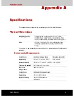
Page 139: ...with 12 1 XGA 256MB RAM 60GB HDD CD RW DVD ROM drive modem LAN Wireless LAN battery pack Size 279 w 238 d 34 8 h millimeters not including parts that extend beyond the main body Conditions Ambient temperature Relative humidity Operating 5 C 41 F to 35 C 95 F 20 to 80 Non operating 20 C 4 F to 65 C 149 F 10 to 95 Thermal Gradient 20 C per hour maximum Wet bulb temperature 26 C maximum Conditions Al...

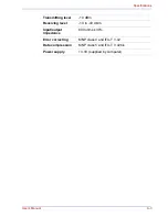
Page 140: ...ions Communication system Data Full duplex Fax Half duplex Communication protocol Data ITU T Rec Former CCITT Bell Fax ITU T Rec Former CCITT V 21 V 22 V 22bis V 32 V 32bis V 34 V 90 103 212A V 17 V 29 V 27ter V 21 ch2 Communication speed Data transmission and reception 300 1200 2400 4800 7200 9600 12000 14400 16800 19200 21600 24000 26400 28800 31200 33600 bps Data reception only with V 90 28000 ...

Page 141: ...cations Transmitting level 10 dBm Receiving level 10 to 40 dBm Input output impedance 600 ohms 30 Error correcting MNP class 4 and ITU T V 42 Data compression MNP class 5 and ITU T V 42bis Power supply 3 3V supplied by computer ...

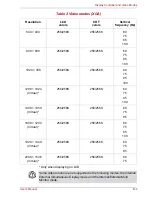
Page 142: ...ideo mode which uses industry standard rules to govern the screen resolution and the maximum number of colors that can be displayed on screen Software written for a given video mode will run on any computer that supports the mode The computer s display controller supports all VGA and Super VGA modes the most widely used industry standards Video modes The computer supports video modes defined in th...

Page 143: ...s 8 8 16 of 256K 16 of 256K 70 0 1 VGA Text 40 25 Characters 8 14 16 of 256K 16 of 256K 70 2 3 VGA Text 80 25 Characters 8 14 16 of 256K 16 of 256K 70 0 1 VGA Text 40 25 Characters 9 16 16 of 256K 16 of 256K 70 2 3 VGA Text 80 25 Characters 9 16 16 of 256K 16 of 256K 70 4 5 VGA Grph 320 200 Pels 8 8 4 of 256K 4 of 256K 70 6 VGA Grph 640 200 Pels 8 8 2 of 256K 2 of 256K 70 7 VGA Text 80 25 Characte...

Page 144: ...Vertical Hz D VGA Grph 320 200 Pels 8 8 16 of 256K 16 of 256K 70 E VGA Grph 640 200 Pels 8 8 16 of 256K 16 of 256K 70 F VGA Grph 640 350 Pels 8 14 Mono Mono 70 10 VGA Grph 640 350 Pels 8 14 16 of 256K 16 of 256K 70 11 VGA Grph 640 480 Pels 8 16 2 of 256K 2 of 256K 60 12 VGA Grph 640 480 Pels 8 16 16 of 256K 16 of 256K 60 13 VGA Grph 320 200 Pels 8 8 256 of 256K 256 of 256K 70 ...

Page 145: ...75 85 100 1024 768 256 256K 256 256K 60 75 85 100 1280 1024 Virtual 256 256K 256 256K 60 75 85 100 1400 1050 Virtual 256 256K 256 256K 60 75 85 1600 1200 Virtual 256 256K 256 256K 60 75 85 100 1920 1440 Virtual 256 256K 256 256K 60 75 85 2048 1536 Virtual 256 256K 256 256K 60 75 Some video modes are not supported in the following modes the Internal External Simultaneous Display mode and the Intern...

Page 146: ...K 64K 60 75 85 100 1024 768 64K 64K 64K 64K 60 75 85 100 1280 1024 Virtual 64K 64K 64K 64K 60 75 85 100 1400 1050 Virtual 64K 64K 64K 64K 60 75 85 1600 1200 Virtual 64K 64K 64K 64K 60 75 85 100 1920 1440 Virtual 64K 64K 64K 64K 60 75 85 2048 1536 Virtual 64K 64K 64K 64K 60 75 Some video modes are not supported in the following modes the Internal External Simultaneous Display mode and the Internal ...

Page 147: ...6M 16M 60 75 85 100 1024 768 16M 16M 16M 16M 60 75 85 100 1280 1024 Virtual 16M 16M 16M 16M 60 75 85 100 1400 1050 Virtual 16M 16M 16M 16M 60 75 85 1600 1200 Virtual 16M 16M 16M 16M 60 75 85 100 1920 1440 Virtual 16M 16M 16M 16M 60 75 2048 1536 Virtual 16M 16M 16M 16M 60 75 Some video modes are not supported in the following modes the Internal External Simultaneous Display mode and the Internal Ex...

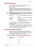
Page 148: ...ed by the Wi Fi Alliance The Wi Fi CERTIFIED logo is a certification mark of the Wi Fi Alliance Network Operating System Q Microsoft Windows Networking Media Access Protocol Q CSMA CA Collision Avoidance with Acknowledgment ACK Data Rate Q Theoretical maximum speed 54Mbps IEEE802 11g Q Theoretical maximum speed 11Mbps IEEE802 11b The Transmit Rate xx Mbit s is the theoretical maximum speed under t...

Page 149: ...antennas are placed near metal surfaces and solid high density materials Q Range is also impacted due to obstacles in the signal path of the radio that may either absorb or reflect the radio signal Supported Frequency Sub bands Subject to the radio regulations that apply in the countries regions your Wireless LAN card may support a different set of 2 4 GHz channels Consult your Authorized Wireless...

Page 150: ...y the Wireless LAN Access Point When roaming between different access points the station can dynamically switch to another channel if required Q For Wireless LAN cards installed in wireless clients that operating in a peer to peer mode the card will use the default channel 10 Q In a Wireless LAN Access Point the Wireless LAN card will use the factory set default channel printed in bold unless the ...

Page 151: ...rds must meet the following specifications Certification agencies Length Minimum 2 meters Wire size Minimum 0 75 mm2 Current rating Minimum 2 5 amperes Voltage rating 125 or 250 VAC depending on country region s power standards U S and Canada UL listed and CSA certified No 18 AWG Type SVT or SPT 2 two conductor Australia AS Japan DENANHO Europe Austria OVE Italy IMQ Belgium CEBEC The Netherlands K...

Page 152: ...V as designated in the U S National Electrical code handbook and the Canadian Electrical Code Part II The following illustrations show the plug shapes for the U S A and Canada the United Kingdom Australia and Europe France UTE Switzerland SEV Germany VDE United Kingdom BSI USA and Canada Australia Europe United Kingdom AS approved Approved by the BS approved UL approved CSA approved appropriate ag...

Page 153: ...on form to the address below To register the theft online please follow these procedures Q Visit www toshiba europe com on the Internet In the product area choose Computer Systems Q In the Computer Systems page open the Support Downloads menu and choose the Stolen Units Database option Your entries are used to track your computer at our service points Always take care of your computer and try to p...

Page 154: ...ical Service and Support Leibnizstr 2 93055 Regensburg Germany Fax number 49 0 941 7807 921 Owner s details Country stolen Machine type e g Satellite A50 Model number e g PSA50 YXT Serial number e g 12345678G Date stolen Last name first name Company Street Postal Code City Country Phone Fax Year Month Day ...

Page 155: ... BIOS basic input output system CD ROM Compact Disc Read Only Memory CD RW Compact Disc ReWritable CMOS complementary metal oxide semiconductor CPU central processing unit CRT cathode ray tube DC direct current DDC display data channel DMA direct memory access DOS disk operating system DVD digital versatile disc DVD R Digital Versatile Disc Recordable DVD RAM Digital Versatile Disc Random Access M...

Page 156: ...l asynchronous receiver transmitter USB Universal Serial Bus VESA Video Electronic Standards Association VGA video graphics array VRT voltage reduction technology WXGA wide extended graphics array XGA extended graphics array A adaptor A device that provides an interface between two dissimilar electronic devices For example the AC adaptor modifies the power from a wall outlet for use by the compute...

Page 157: ...backup A duplicate copy of files kept as a spare in case the original is destroyed batch file A file that can be executed from the system prompt containing a sequence of operating system commands or executable files binary The base two number system composed of zeros and ones off or on used by most digital computers The right most digit of a binary number has a value of 1 the next a value of 2 the...

Page 158: ...emory is a high capacity disc that can be read from but not written to The CD ROM drive uses a laser rather than magnetic heads to read data from the disc CD R A Compact Disc Recordable disc can be written once and read many times See also CD ROM CD RW A Compact Disc ReWritable disc can be rewritten many times See also CD ROM character Any letter number punctuation mark or symbol used by the compu...

Page 159: ...s the functions of a specific internal or peripheral device e g keyboard controller co processor A circuit built into the processor that is dedicated to intensive math calculations CPS Characters Per Second Typically used to indicate the transmission speed of a printer CPU Central Processing Unit The portion of the computer that interprets and executes instructions CRT Cathode Ray Tube A vacuum tu...

Page 160: ...mputer system or application Computer system documentation typically includes procedural and tutorial information as well as system functions DOS Disk Operating System See operating system driver A software program generally part of the operating system that controls a specific piece of hardware frequently a peripheral device such as a printer or mouse DVB T Digital Video Broadcasting Terrestrial ...

Page 161: ...reverse data transmission and run length encoding RLE support F fast infrared An industry standard that enables cableless infrared serial data transfer at speeds of up to 4 Mbps file A collection of related information a file can contain data programs or both firmware A set of instructions built into the hardware which controls and directs a microprocessor s activities floppy disk A removable disk...

Page 162: ... for various hardware components I icon A small graphic image displayed on the screen or in the indicator panel In Windows an icon represents an object that the user can manipulate i LINK IEEE1394 This port enables high speed data transfer directly from external devices such as digital video cameras input The data or instructions you provide to a computer communication device or other peripheral d...

Page 163: ...l to 1024 bytes See also byte and megabyte L level 2 cache See cache Light Emitting Diode LED A semiconductor device that emits light when a current is applied Liquid Crystal Display LCD Liquid crystal sealed between two sheets of glass coated with transparent conducting material The viewing side coating is etched into character forming segments with leads that extend to the edge of the glass Appl...

Page 164: ...oppy disk you can use to store programs and data but you cannot use to start the computer See system disk nonvolatile memory Memory usually read only ROM that is capable of permanently storing information Turning the computer s power off does not alter data stored in nonvolatile memory numeric keypad overlay A feature that allows you to use certain keys on the keyboard to perform numeric entry or ...

Page 165: ...uter sends and receives data to and from devices or other computers Power Saver Utility A TOSHIBA utility that lets you set the parameters for various power saving functions printed circuit board PCB A hardware component of a processor to which integrated circuits and other components are attached The board itself is typically flat and rectangular and constructed of fiberglass to form the attachme...

Page 166: ...The electronic methodology used in serial data transmission soft key Key combinations that emulate keys on the IBM keyboard change some configuration options stop program execution and access the numeric keypad overlay software The set of programs procedures and related documentation associated with a computer system Specifically refers to computer programs that direct and control the computer sys...

Page 167: ...ate with several devices connected in a chain to a single port on the computer V VGA Video Graphics Array is an industry standard video adaptor that lets you run any popular software volatile memory Random access memory RAM that stores information as long as power is supplied to the computer W warm start Restarting or resetting a computer without turning it off window A portion of the screen that ...

Page 168: ...0 replacing 6 11 C Cache memory 1 3 Cleaning the computer 4 17 Cooling vents 2 5 D DC IN indicator 2 9 6 3 Display 1 4 2 7 automatic power off 1 8 brightness decreases 5 5 controller 1 4 B 1 hinge 2 7 opening 3 6 DLA for TOSHIBA 1 11 Documentation list 1 2 DVD Multi drive location 2 3 using 4 3 DVD ROM CD R RW drive 1 4 location 2 3 using 4 3 writing 4 8 E Environment 3 1 Equipment checklist 1 1 E...

Page 169: ...window 7 1 I i LINK 1 5 2 2 8 14 connecting 8 15 disconnecting 8 15 precautions 8 14 K Keyboard 1 5 5 1 emulating keys on enhanced 5 2 Function keys F1 F12 5 2 hot keys 5 3 typewriter keys 5 1 Windows special keys 5 7 Keypad overlay 1 8 5 7 arrow mode 5 7 numeric mode 5 8 temporarily using normal keyboard overlay on 5 8 temporarily using overlay overlay off 5 8 turning on the overlays 5 7 L LAN 1 ...

Page 170: ...ernal LCD display panel 9 7 Keyboard 9 7 Memory expansion 9 13 Modem 9 14 Overheating power down 9 4 PC card 9 10 Pointing device 9 10 Power 9 4 Real Time Clock 9 6 Self test 9 4 Sound system 9 13 Standby Hibernation 9 16 Support from TOSHIBA 9 16 System start up 9 3 USB 9 12 USB floppy disk drive 9 9 Wireless LAN 9 15 Processor 1 3 R RecordNow 1 11 Restarting the computer 3 11 S SD card 1 5 care ...

Page 171: ...SHIBA Theft Registration E 2 TOSHIBA Utilities 1 7 TOSHIBA Zooming Utility 1 11 Touch Pad 1 5 location 2 7 problems 9 10 using 4 1 TV 8 12 U USB 1 5 location 2 3 2 4 USB floppy disk 1 4 additional 8 11 using 4 2 Video modes B 1 Video RAM 1 3 W Wireless communication switch 1 7 4 14 indicator 4 15 Wireless LAN 1 6 ...

Reviews: