background image

60

Q9 ASD Quick Start Guide

Short Circuit Protection Recommendations

Table 9. 230/240 and 400/480-Volt ASD Recommended Circuit Breaker Selection.

Model Number 

VT130Q9U

HP

Continuous Output Current

(Amps)

Circuit Breaker Part Number

2010

0.75

3.7

Contact Toshiba Customer Service

2015

1.0

4.8

Contact Toshiba Customer Service

2025

2.0

7.8

Contact Toshiba Customer Service

2035

3.0

11.0

HLL36025

2055

5.0

17.5

HLL36025

2080

7.5

25.3

HLL36040

2110

10

32.2

HLL36050

2160

15

48.3

HLL36070

2220

20

62.1

HLL36090

2270

25

78.2

HLL36100

2330

30

92.0

HLL36100

2400

40

120

HLL36125

2500

50

150

HLL36150

2600

60

177

JLL36200

4015

1.0

2.1

Contact Toshiba Customer Service

4025

2.0

3.4

Contact Toshiba Customer Service

4035

3.0

4.8

Contact Toshiba Customer Service

4055

5.0

7.6

HLL36025

4080

7.5

11

HLL36040

4110

10

14

HLL36050

4160

15

21

HLL36070

4220

20

27

HLL36090

4270

25

34

HLL36100

4330

30

40

HLL36100

4400

40

52

HLL36125

4500

50

65

HLL36150

4600

60

77

JLL36200

4750

75

96

JLL36225

410K

100

124

JLL36250

412K

125

156

LIL36300

415K

150

180

LIL36300

420K

200

240

LIL36400

425K

250

302

LIL36400

430K

300

361

Contact Toshiba Customer Service

435K

350

414

Contact Toshiba Customer Service

440K

400

477

Contact Toshiba Customer Service

Phone: 800.894.0412 - Fax: 888.723.4773 - Web: www.clrwtr.com - Email: info@clrwtr.com

Summary of Contents for Q9 True Torque Control2 Adjustable Speed Drive

Page 1: ...Document Number 59490 003 Date April 2010 Q9 ASD Quick Start Guide Phone 800 894 0412 Fax 888 723 4773 Web www clrwtr com Email info clrwtr com ...

Page 2: ...Phone 800 894 0412 Fax 888 723 4773 Web www clrwtr com Email info clrwtr com ...

Page 3: ...Q9 ASD Quick Start Guide Document Number 59490 003 Date April 2010 Phone 800 894 0412 Fax 888 723 4773 Web www clrwtr com Email info clrwtr com ...

Page 4: ...Phone 800 894 0412 Fax 888 723 4773 Web www clrwtr com Email info clrwtr com ...

Page 5: ...e For a more in depth description of the many features of the Q9 ASD see the Q9 ASD Installation and Operation Manual The Q9 ASD Installation and Operation Manual may be downloaded from Toshiba website or a printed copy may be acquired from your Toshiba Sales Representative Important Notice The instructions contained in this guide are not intended to cover all details or variations in equipment ty...

Page 6: ...the guide completely before installing operating performing maintenance or disposing of this equipment This guide and the accompanying drawings should be considered a permanent part of the equipment and should be readily available for reference and review Dimensions shown in the guide are in metric and or the English equivalent Because of our commitment to continuous improvement Toshiba Internatio...

Page 7: ...ATIONAL CORPORATION Q9 Adjustable Speed Drive Please complete the Warranty Card supplied with the ASD and return it to Toshiba by prepaid mail This will activate the 12 month warranty from the date of installation but shall not exceed 18 months from the shipping date Complete the following information and retain for your records Model Number ________________________________________________________...

Page 8: ...Phone 800 894 0412 Fax 888 723 4773 Web www clrwtr com Email info clrwtr com ...

Page 9: ...tup Requirements 8 Operational and Maintenance Precautions 9 Installation and Connections 10 Installation Notes 10 Mounting the ASD 11 Connecting the ASD 12 Lead Length Specifications 16 I O and Control 17 Electronic Operator Interface 24 EOI Operation 24 EOI Remote Mounting 24 EOI Features 25 System Configuration and Menu Options 27 Root Menu Items 27 System Operation 47 Operation Local 47 Defaul...

Page 10: ...ii Q9 ASD Quick Start Guide Phone 800 894 0412 Fax 888 723 4773 Web www clrwtr com Email info clrwtr com ...

Page 11: ...ety information that must be carefully followed The word DANGER preceded by the safety alert symbol indicates that an imminently hazardous situation exists that if not avoided will result in serious injury to personnel or loss of life The word WARNING preceded by the safety alert symbol indicates that a potentially hazardous situation exists that if not avoided could result in serious injury to pe...

Page 12: ...or to indicate an imminently hazardous situation that may result in serious injury severe property and equipment damage or loss of life if safe procedures or methods are not followed as outlined in this guide Qualified Personnel Installation operation and maintenance shall be performed by Qualified Personnel Only A Qualified Person is one that has the skills and knowledge relating to the construct...

Page 13: ...may be required after moving equipment Contact your Toshiba Sales Representative to report discrepancies or for assistance if required Handling and Storage Use proper lifting techniques when moving the ASD including properly sizing up the load getting assistance and using a forklift if required Store in a well ventilated location and preferably in the original carton if the equipment will not be u...

Page 14: ...bers metal particles explosive corrosive mists or gases or sources of electrical noise are present The installation location shall not be exposed to direct sunlight DO NOT obstruct the ventilation openings Allow proper clearance spaces for installation Refer to the section titled Mounting the ASD on pg 11 for further information on ventilation requirements The ambient operating temperature range o...

Page 15: ...Grounding Capacitor Switch The ASD is equipped with leak reduction capacitors which are used to reduce the EMI leakage via the 3 phase power input circuit and for compliance with the Electromagnetic Compatibility Directive EMC The effective value of the capacitor may be increased reduced or removed entirely via the Selector Switch Switching Bar or the Switching Screw the type used is typeform spec...

Page 16: ... to personnel DO NOT connect resistors across terminals PA PC or PO PC This may cause a fire Ensure the correct phase sequence and the desired direction of motor rotation in the Bypass mode if applicable Turn the power on only after attaching and or securing the front cover Protection Ensure that primary protection exists for the input wiring to the equipment This protection must be able to interr...

Page 17: ...tion specific system integration information if required Personnel Protection Installation operation and maintenance shall be performed by Qualified Personnel Only A thorough understanding of the ASD will be required before the installation operation or maintenance of the ASD Rotating machinery and live conductors can be hazardous and shall not come into contact with personnel Personnel should be ...

Page 18: ...rotective features is highly recommended i e E Off Overload Protection etc The operating controls and system status indicators should be clearly readable and positioned where the operator can see them without obstruction Additional warnings and notifications shall be posted at the equipment installation location as deemed required by Qualified Personnel Follow all warnings and precautions and do n...

Page 19: ...efore opening the door of the ASD once the ASD power has been turned off Turn the power on only after attaching or closing the front cover and DO NOT remove or open the front cover of the ASD when the power is on DO NOT attempt to disassemble modify or repair the ASD Call your Toshiba Sales Representative for repair information DO NOT place any objects inside of the ASD If the ASD should emit smok...

Page 20: ...output contactor is opened DO NOT open and then close a secondary magnetic contactor between the ASD and the motor unless the ASD is off and the motor is not rotating Note Re application of power via a secondary contact while the Q9 ASD is on or while the motor is still turning may cause ASD damage The Q9 ASD input voltage should remain within 10 of the specified input voltage range Input voltages...

Page 21: ...e ventilation DO NOT operate the ASD with the enclosure door open The ambient operating temperature rating of the Q9 ASD is 14 to 104 F 10 to 40 C When installing adjacent ASDs horizontally Toshiba recommends at least 5 cm of space between adjacent units However horizontally mounted ASDs may be installed side by side with no space in between the adjacent units side by side installations require th...

Page 22: ...ted across these terminals See Figure 20 on pg 22 PA and PB are used for the DBR connection The DBR function is not used on the Q9 ASD PC is the negative terminal of the DC bus R L1 S L2 and T L3 are the 3 phase input supply terminals for the ASD U T1 V T2 and W T3 are the output terminals of the ASD that connect to the motor The location of the Charge LED for the smaller typeform ASD is provided ...

Page 23: ...2008 NEC Article 310 adjustment factors Note National and local codes should be referenced when running more than three conductors in the same conduit Install a molded case circuit breaker MCCB or fuse between the 3 phase power source and the ASD in accordance with the fault current setting of the ASD and 2008 NEC Article 430 The ASD is designed and tested to comply with UL Standard 508C Modificat...

Page 24: ...ound Connect a surge suppressor to every electromagnetic contactor and every relay installed near the ASD Install noise filters as required Grounding Capacitor The Grounding Capacitor plays a role in minimizing the effects of leakage current through the ASD system and through ground paths to other systems Leakage current may cause the improper operation of earth leakage current breakers leakage cu...

Page 25: ...Large default setting or Small by pushing or pulling the switch actuator respectively Figure 6 The Grounding Capacitor Bar is used on typeforms 200 volt 75 HP and the 100 HP 460 volt 125 HP and the 150 HP The value may be set to Large or Small default setting by connecting or disconnecting the switching bar respectively Figure 7 The Grounding Capacitor Screw is used on typeforms 460 volt 175 HP an...

Page 26: ... Contact the Toshiba Customer Support Center for application assistance when using lead lengths in excess of those listed Exceeding the peak voltage rating or the allowable thermal rise time of the motor insulation will reduce the life expectancy of the motor When operating in the Vector Control mode the carrier frequency should be set to 2 2 kHz or above Table 1 Lead Length Recommendations Model ...

Page 27: ...ommand Multifunctional programmable discrete output Figure 16 on pg 21 O2A B OUT2 Reach Frequency Multifunctional programmable discrete output FLA Fault relay N O Figure 19 on pg 21 FLB Fault relay N C FLC Fault relay Common RR Analog Input Frequency Mode 1 Multifunction programmable analog input 0 0 to 10 volt input 0 Hz to Maximum Frequency Figure 11 on pg 21 RX Unassigned Multifunctional progra...

Page 28: ...l may be programmed to any of the functions listed in the Q9 ASD Installation and Operation Manual See F111 R The default setting for this terminal is Reverse run command The R terminal is activated by connecting CC to this terminal Sink mode This input terminal may be programmed to any of the functions listed in the Q9 ASD Installation and Operation Manual See F112 S1 The default setting for this...

Page 29: ...VDC at 200 mA power supply for customer use This terminal references CCA PP The function of output PP is to provide a 10 VDC 10 mADC output that may be divided using a potentiometer The tapped voltage is applied to the RR input to provide manual control of the RR programmed function This terminal references CCA O1A B OUT1A B The default function assigned to this terminal is Damper Command This out...

Page 30: ...inal Board Sink Source TB1 TB2 TB3 TB4 See the section titled Terminal Descriptions on pg 18 for terminal descriptions See the section titled Cable Terminal Specifications on pg 58 for information on the proper cable terminal sizes and torque specifications when making Terminal Board connections FLC LB FLA Note The relay is shown in the normal operating condition During a faulted condition the rel...

Page 31: ...gure 11 RR Input Figure 12 RX Input Figure 13 V I Input Figure 14 P24 Output Figure 15 PP Output Figure 16 OUT1 OUT2 Output Figure 17 FP Output Figure 18 AM FM Output Figure 19 Fault Relay shown not faulted Phone 800 894 0412 Fax 888 723 4773 Web www clrwtr com Email info clrwtr com ...

Page 32: ...als are referenced to CC The RR RX P24 and the PP analog terminals are referenced to CCA The isolated V I analog terminal references IICC Note When connecting multiple wires to any of ASD terminals do not connect a solid wire and a stranded wire to the same terminal Phone 800 894 0412 Fax 888 723 4773 Web www clrwtr com Email info clrwtr com ...

Page 33: ...e connected to the 3 phase input power U T1 V T2 and W T3 are connected to the motor The 3 phase input voltage is within the specified tolerance There are no shorts and all grounds are secure All personnel are at a safe distance away from the motor and or the motor driven equipment Phone 800 894 0412 Fax 888 723 4773 Web www clrwtr com Email info clrwtr com ...

Page 34: ...y bus voltage torque etc The software used with the Q9 ASD is menu driven thus making it a select and click environment The operating parameters of a motor may be selected and viewed or changed using the EOI or via communications EOI Remote Mounting The EOI may be mounted remotely using the optional ASD MTG KITQ9 The kit contains all of the hardware required to mount the EOI of the 9 Series ASD re...

Page 35: ...Menu until reaching the Frequency Command screen See Figure 22 on pg 27 Further ESC key entries are ignored Run Key Issues the Run command while in the Local mode The Run key LED Illuminates green while stopped Illuminates red while running or while exciting the motor Mode Key Provides a means to access the five root menus Pressing the Mode Key key repeatedly loops the system through the five root...

Page 36: ...ting Repeated ESC key entries at any time takes the menu back one level each time the ESC key is pressed until the Frequency Command screen is reached Further ESC key entire are ignored LCD Screen Installation Note When installing the LCD screen module of the EOI ensure that the left side of the display is inserted first with the top and bottom catches See Phillips screws at underside of screen se...

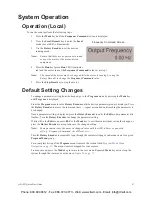
Page 37: ...ile operating in the Local mode Local LED is illuminated the running frequency of the motor may be set from the Frequency Command screen Using the Rotary Encoder enter the Frequency Command value connect ST to CC provide a Run command F and or R and then press the Run key The motor will run at the Frequency Command speed and may be changed while running See Operation Local on pg 47 for more inform...

Page 38: ...I V I Reference 2 VI II V I Frequency 2 PID Control Switching PID Feedback Selection PID Feedback Delay Filter PID Feedback Proportional P Gain PID Feedback Integral I Gain PID Deviation Upper Limit PID Deviation Lower Limit PID Feedback Differential D Gain Process Upper Limit Process Lower Limit PID Control Wait Time PID Output Upper Limit PID Output Lower Limit Process Increasing Rate Process De...

Page 39: ...ercentage of the rated capacity of the ASD Discrete Input Terminals Displays any activated discrete input terminals of the Terminal Board Discrete Output Terminals Displays any activated discrete output terminals of the Terminal Board Run Time Displays the Cumulative Run Time in hours Select Clear Run Timer at F007 to reset this reading Compensation Frequency Displays the Output Frequency after th...

Page 40: ...gnitude of the function assigned to this terminal relative to the full scale reading of the AM terminal This terminal may be configured at F670 for application specific suitability Fault Displays the active fault or No Error if there are no errors Past Trip 1 This function records and displays the last trip incurred Subsequent trips will replace Past Trip 1 As trip records are replaced they are sh...

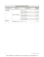
Page 41: ...am Mode Menu Navigation Primary Menu Sub Menu Parameter Name Parameter Number OUTPUT FREQUENCY N A SETUP Setup Acceleration Time 1 F009 Decel Time 1 F010 Upper Limit Frequency F012 Lower Limit Frequency F013 V I Reference 1 F201 V I Frequency 1 F202 V I Reference 2 F203 V I Frequency 2 F204 Type Reset F007 V f Pattern F015 Electronic Thermal Protection 1 F600 PID SETUP PID Setup Command Mode F003 ...

Page 42: ...Output Upper Limit F370 PID Output Lower Limit F371 Process Increasing Rate F372 Process Decreasing Rate F373 Upper Limit Frequency F012 Lower Limit Frequency F013 Low Output Disable Time F256 Acceleration Time 1 F009 Decel Time 1 F010 Frequency Command Panel N A PID Feedback PID Feedback Selection F360 PROGRAM Program Search Direct Access Fundamental 1 Maximum Output Frequency F011 Program Mode M...

Page 43: ...ntal 2 Base Frequency 2 F170 Base Voltage 2 F171 Torque Boost 2 F172 Electronic Thermal Protection 2 F173 Acceleration Time 2 F500 Deceleration Time 2 F501 Accel Decel Pattern 2 F503 Accel Decel Switching Frequency 1 F505 Panel Control Panel Direction F008 Panel Stopping Pattern F721 Panel Accel Decel Selection F504 Switch On The Fly F295 Lock CMOD FMOD F736 Program Mode Menu Navigation Primary Me...

Page 44: ...21 LI4 Terminal F122 LI5 Terminal F123 Input Terminals LI6 Terminal F124 LI7 Terminal F125 LI8 Terminal F126 On Terminal F110 Direction Priority F105 Input Priority F106 Output Terminals OUT1 Terminal F130 OUT2 Terminal F131 FL Terminal F132 OUT3 Terminal F133 OUT4 Terminal F134 Program Mode Menu Navigation Primary Menu Sub Menu Parameter Name Parameter Number Phone 800 894 0412 Fax 888 723 4773 W...

Page 45: ...243 Run Frequency F241 Run Frequency Hysteresis F242 Jump Frequency 1 F270 Jump Frequency 1 Bandwidth F271 Jump Frequency 2 F272 Jump Frequency 2 Bandwidth F273 Jump Frequency 3 F274 Jump 3 Frequency Bandwidth F275 PWM Carrier Frequency F300 LCD Contrast F790 V I Input Loss Response F644 V I Input Loss Detection Level F633 Preset Speed 14 F293 Program Mode Menu Navigation Primary Menu Sub Menu Par...

Page 46: ... Injection Braking Time F252 DC Injection On During Direction Change F253 Shaft Stationary F254 kWH Memory Selection F748 kWH Units Selection F749 Preset Speeds Preset Speed 1 F018 Preset Speed 2 F019 Preset Speed 3 F020 Preset Speed 4 F021 Preset Speed 5 F022 Preset Speed 6 F023 Preset Speed 7 F024 Preset Speed 8 F287 Preset Speed 9 F288 Preset Speed 10 F289 Program Mode Menu Navigation Primary M...

Page 47: ...Over Voltage Stall Level F626 Emergency Off Mode Selection F603 Emergency Off DC Injection Time F604 Number of Retries F303 Speed Search Selection F301 Ridethrough Mode F302 Ridethrough Time F310 Under Voltage Trip F627 Overload Reduction Starting Frequency F606 Soft Stall Selection F017 Trip Save F602 Cooling Fan Control F620 Run Time Alarm Setting F621 Output Phase Loss F605 Program Mode Menu Na...

Page 48: ...vel Negative Torque F617 Over Torque Detection Time F618 Over Torque Detection Hysteresis F619 Input Phase Loss F608 Adding Input Selection F660 Multiplying Input Selection F661 PM Current Level F640 PM Current Time F641 Feedback Settings PID Switching F359 Input Feedback Selection F360 Delay Filter F361 Proportional Gain F362 Integral Gain F363 Upper Deviation Limit F364 Program Mode Menu Navigat...

Page 49: ...ate F820 Parity RS485 2 and 4 Wire F801 Time Out Time RS485 2 and 4 Wire F803 Time Out Action RS485 2 and 4 Wire F804 Send Wait Time 2 Wire F805 Send Wait Time 4 Wire F825 ASD to ASD Comm RS485 2 Wire F806 ASD to ASD Comm RS485 4 Wire F826 Communication Reference Selection F810 Communication Reference 1 F811 Communication Frequency 1 F812 Communication Reference 2 F813 Communication Frequency 2 F8...

Page 50: ...cteristic F685 AM Bias Adjustment F686 Utility Group Type Reset F007 Command Mode F003 Frequency Mode 1 F004 PWM Carrier Frequency F300 Panel Frequency Lockout F730 CPU Version N A CPU Revision MC Version MC Revision Control EEPROM Version ASD Typeform Frequency Multiplier F702 User Unit Type F703 Units for Voltage Current F701 Program Mode Menu Navigation Primary Menu Sub Menu Parameter Name Para...

Page 51: ... Slip Gain F401 Autotuning Control 2 F402 Motor Rated Capacity F405 Motor Rated Current F406 Motor Rated RPM F407 Motor Constant 1 F410 Motor Constant 2 F411 Motor Constant 3 F412 Motor Constant 4 F413 Frequency Settings Reference Priority Selection F200 Frequency Mode 2 F207 Mode 1 Mode 2 Switching Frequency F208 V I Reference 1 F201 V I Frequency 1 F202 Program Mode Menu Navigation Primary Menu ...

Page 52: ...erence 2 F215 RX Reference 1 F216 RX Frequency 1 F217 RX Reference 2 F218 RX Frequency 2 F219 RX Torque Reference 1 F220 RX Torque Reference 2 F221 RX2 Reference 1 F222 RX2 Frequency 1 F223 RX2 Reference 2 F224 RX2 Frequency 2 F225 BIN Reference 1 F228 BIN Frequency 1 F229 BIN Reference 2 F230 BIN Frequency 2 F231 Program Mode Menu Navigation Primary Menu Sub Menu Parameter Name Parameter Number P...

Page 53: ...rget 3 F904 Output Function Assigned F905 My Function Unit 2 Input Function Target 1 F906 Input Function Command 1 F907 Input Function Target 2 F908 Input Function Command 2 F909 Input Function Target 3 F910 Output Function Assigned F911 My Function Unit 3 Input Function Target 1 F912 Input Function Command 1 F913 Input Function Target 2 F914 Input Function Command 2 F915 Input Function Target 3 F...

Page 54: ...tion Command 2 F944 Input Function Target 3 F945 Output Function Assigned F946 My Function Unit 6 Input Function Target 1 F947 Input Function Command 1 F948 Input Function Target 2 F949 Input Function Command 2 F950 Input Function Target 3 F951 Output Function Assigned F952 My Function Unit 7 Input Function Target 1 F953 Input Function Command 1 F954 Input Function Target 2 F955 Input Function Com...

Page 55: ... Data 4 F926 My Function Frequency Data 5 F927 My Function Time Data 1 F928 My Function Time Data 2 F929 My Function Time Data 3 F930 My Function Time Data 4 F931 My Function Time Data 5 F932 My Function Count Data 1 F933 My Function Count Data 2 F934 My Function Analog Input Target 11 F959 Assigned Object 11 F961 Input Target 21 F962 Assigned Object 21 F964 My Function Monitor Output Function 11 ...

Page 56: ...tput Function 31 F969 Output Command 31 F970 Output Function 41 F971 Output Command 41 F972 MONITOR Monitor Read Only See Monitor Mode on pg 29 N A Program Mode Menu Navigation Primary Menu Sub Menu Parameter Name Parameter Number Phone 800 894 0412 Fax 888 723 4773 Web www clrwtr com Email info clrwtr com ...

Page 57: ...roup is displayed Press the Rotary Encoder to access the sub menu items repeat as required until reaching the parameter to be changed Once a parameter setting is displayed press the Rotary Encoder to enter the Edit mode parameter title flashes Turn the Rotary Encoder to change the parameter setting While still in the Edit mode press ESC or the Mode key to exit the menu without saving the change or...

Page 58: ...ue scrolling either forward or reverse respectively With each Up or Down click from a stop the system scrolls and stops at the next parameter that has been changed Press the Rotary Encoder once while the system is halted at a changed parameter to enter the Edit mode parameter title flashes Turn the Rotary Encoder to change the setting While still in the Edit mode press the Mode key to exit the Sea...

Page 59: ...nd for placing orders Q9 Part Numbering Convention Note The Type 1 enclosed versions of these drives meet or exceed the specification UL 50 1995 the Standard for Heating and Cooling Equipment and complies with the applicable requirements for installation in a compartment handling conditioned air Note All Toshiba ASD enclosures carry an IP20 rating Phone 800 894 0412 Fax 888 723 4773 Web www clrwtr...

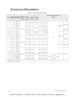
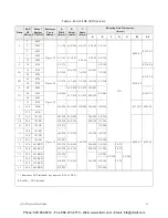
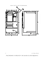
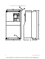
Page 60: ...3 210 7 6 194 7 5 190 0 118 3 0 0 276 7 0 5B 15 2160 9 1 230 16 7 425 7 5 191 15 2 386 8 3 210 20 2220 6 25 2270 Figure 24 9 4 240 16 5 420 8 3 212 15 9 403 8 1 206 0 295 7 5 30 2330 7B 40 2400 12 6 320 21 7 550 9 5 242 20 7 525 11 0 280 0 177 4 5 0 394 10 50 2500 60 2600 9 75 2750 Figure 26 12 2 310 26 7 680 14 6 370 25 6 650 9 8 250 0 224 5 7 0 472 12 100 210K 10 125 212K 13 8 350 30 8 782 29 8 ...

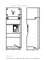
Page 61: ... 0 295 7 5 7A 50 4500 Figure 25 21 7 550 9 5 242 20 8 529 60 4600 8 75 4750 12 6 320 24 8 630 11 4 290 23 8 605 11 0 280 0 177 4 5 0 394 10 100 410K 125 412K 9 150 415K Figure 26 12 2 310 26 8 680 14 6 370 25 6 650 9 8 250 0 224 5 7 0 472 12 10 200 420K 13 0 350 30 8 782 29 8 758 11 7 298 11 250 425K 13 8 334 37 4 950 36 2 920 11 2 285 12 300 430K 16 9 430 13 8 350 350 435K 13 400 440K 23 0 585 21...

Page 62: ...52 Q9 ASD Quick Start Guide Figure 23 See Table 3 and 4 for Actual Dimensions Phone 800 894 0412 Fax 888 723 4773 Web www clrwtr com Email info clrwtr com ...

Page 63: ...Q9 ASD Quick Start Guide 53 Figure 24 See Table 3 and 4 for Actual Dimensions Phone 800 894 0412 Fax 888 723 4773 Web www clrwtr com Email info clrwtr com ...

Page 64: ...54 Q9 ASD Quick Start Guide Figure 25 See Table 4 for Actual Dimensions Phone 800 894 0412 Fax 888 723 4773 Web www clrwtr com Email info clrwtr com ...

Page 65: ...Q9 ASD Quick Start Guide 55 Figure 26 See Table 3 and 4 for Actual Dimensions Phone 800 894 0412 Fax 888 723 4773 Web www clrwtr com Email info clrwtr com ...

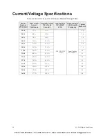
Page 66: ...3 Ph Variable Frequency Typical Motor HP 2010 3 7 A 4 1 A 200 240VAC 10 Input Voltage Level Max 0 75 2015 4 8 A 5 3 A 1 0 2025 7 8 A 8 6 A 2 0 2035 11 0 A 12 1 A 3 0 2055 17 5A 19 3 A 5 0 2080 25 3 A 27 8 A 7 5 2110 32 2 A 35 4 A 10 2160 48 3 A 53 1 A 15 2220 62 1 A 68 3 A 20 2270 78 2 A 86 0 A 25 2330 92 0 A 101 A 30 2400 120 A 132 A 40 2500 150 A 165 A 50 2600 177 A 195 A 60 Phone 800 894 0412 F...

Page 67: ...4025 3 4 A 3 7 A 2 0 4035 4 8 A 5 3 A 3 0 4055 7 6 A 8 4 A 5 0 4080 11 0 A 12 1 A 7 5 4110 14 0 A 15 4 A 10 4160 21 0 A 23 1 A 15 4220 27 0 A 29 7 A 20 4270 34 0 A 37 4 A 25 4330 40 0 A 44 0 A 30 4400 52 0 A 57 2 A 40 4500 65 0 A 71 5 A 50 4600 77 0 A 84 7 A 60 4750 96 0 A 106 A 75 410K 124 A 136 A 100 412K 156 A 172 A 125 415K 180 A 198 A 150 420K 240 A 264 A 200 425K 302 A 332 A 250 430K 361 A 3...

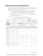
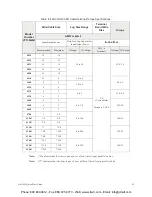
Page 68: ...h the Q9 ASD Note Cable Terminal specifications are based on the rated current of the Q9 ASD and Do Not include the 10 Service Factor Note Use only 75 C copper wire cable for motor and power connections Table 7 230 Volt Q9 ASD Cable Terminal Torque Specifications Model Number VT130Q9U Wire Cable Size Lug Size Range Terminal Board Wire Size Torque AWG or kcmil Input Output Power Wire Size Lug Capac...

Page 69: ...acity for Input Output Power In Lbs N m Recommended Maximum 3Ø Input 3Ø Output TB1 4 Terminals 3Ø Input 3Ø Output 4015 14 10 14 to 10 20 3 core shield Torque to 5 3 0 6 12 4 1 4 4025 14 10 4035 14 10 4055 14 10 4080 14 10 4110 12 8 12 to 8 26 6 3 4160 8 4 10 to 4 4220 8 4 4270 6 3 8 to 2 47 8 5 4 4330 6 3 4400 6 2 4 to 1 0 212 24 4500 4 2 4600 3 2 4750 1 4 0 2 to 300 360 41 410K 1 0 4 0 412K 3 0 4...

Page 70: ...2400 40 120 HLL36125 2500 50 150 HLL36150 2600 60 177 JLL36200 4015 1 0 2 1 Contact Toshiba Customer Service 4025 2 0 3 4 Contact Toshiba Customer Service 4035 3 0 4 8 Contact Toshiba Customer Service 4055 5 0 7 6 HLL36025 4080 7 5 11 HLL36040 4110 10 14 HLL36050 4160 15 21 HLL36070 4220 20 27 HLL36090 4270 25 34 HLL36100 4330 30 40 HLL36100 4400 40 52 HLL36125 4500 50 65 HLL36150 4600 60 77 JLL36...

Page 71: ...ut 17 Disposal 3 Dynamic Braking 8 E Electronic Operator Interface 24 Electronic Operator Interface Features 25 Emergency Off 25 Enclosure Dimensions 49 EOI Features 25 EOI Operation 24 EOI Remote Mounting 24 Equipment Inspection 3 F F 17 18 Fault 30 Fault Relay 21 FLA 17 20 FLB 17 20 FLC 17 20 FM 17 19 FM Output 30 FP 17 19 35 FP Output 21 Frequency at Trip 29 Frequency Command Mode 27 Frequency ...

Page 72: ...rminals 34 35 Output Voltage 29 P P24 19 P24 Output 21 PA 12 Past Trip 1 30 Past Trip 2 30 Past Trip 3 30 Past Trip 4 30 Personnel Protection 7 PID Feedback 29 PID SETUP 31 PID Setup 31 PID Setup Mode 28 PO 12 Power Connections 6 12 PP 17 19 PP Output 21 Preset Speed 36 Program 32 Program Mode Menu Navigation 31 Q Q9 Part Numbering Convention 49 Qualified Personnel 2 R R 17 18 R L1 12 Remote Mode ...

Page 73: ...n Precautions 7 System Operation 47 T T L3 12 TB1 20 TB2 20 TB3 20 TB4 20 Terminal Board 10 17 20 Terminal Descriptions 18 U U T1 12 UL 1995 49 Upper Limit Frequency 31 V V I 30 V I I 19 V I Frequency 31 V I Reference 31 V T2 12 W W T3 12 Warranty Card 4 Phone 800 894 0412 Fax 888 723 4773 Web www clrwtr com Email info clrwtr com ...

Reviews: