background image

E.2


United Kingdom (UK) Keyboard


Appendix E  Key Layout 


E-2                            [CONFIDENTIAL] 


QOSMIO G20  Maintenance Manual (960-511) 


Summary of Contents for QOSMIO G20 Series

Page 1: ...1 Toshiba Personal Computer QOSMIO G20 Maintenance Manual TOSHIBA CORPORATION File Number 960 511 CONFIDENTIAL ...

Page 2: ...efore Toshiba assumes no liability for damages incurred directly or indirectly from errors omissions or discrepancies between any succeeding product and this manual Trademarks IBM is a registered trademark and IBM PC is a trademark of International Business Machines Corporation Intel Intel SpeedStep Centrino Pentium are trademarks or registered trademarks of Intel Corporation or its subsidiaries i...

Page 3: ...ily injury if the safety instruction is not observed CAUTION Caution indicates the existence of a hazard that could result in property damage if the safety instruction is not observed NOTE Note contains general information that relates to your safe maintenance service Improper repair of the computer may result in safety hazards Toshiba requires service technicians and authorized dealers or service...

Page 4: ...scribes how to perform test and diagnostic operations for maintenance service Chapter 4 Replacement Procedures describes the removal and replacement of the FRUs Appendices The appendices describe the following Handling the LCD module Board layout Pin assignment Display codes Key layout Wiring diagrams BIOS Rewrite procedures EC KBC Rewrite procedures Reliability Maintenance of TOSHIBA RAID iv CONF...

Page 5: ...operation Some operations require you to simultaneously use two or more keys We identify such operations by the key top symbols separated by a plus sign For example Ctrl Pause Break means you must hold down Ctrl and at the same time press Pause Break If three keys are used hold down the first two and at the same time press the third User input Text that you are instructed to type in is shown in th...

Page 6: ... 3 2 3 Power Supply Troubleshooting 2 7 2 4 System Board Troubleshooting 2 17 2 5 USB FDD Troubleshooting 2 37 2 6 2 5 HDD Troubleshooting 2 41 2 7 Keyboard Troubleshooting 2 46 2 8 Touch pad Troubleshooting 2 48 2 9 Display Troubleshooting 2 50 2 10 Optical Disk Drive Troubleshooting 2 53 2 11 Modem Troubleshooting 2 55 2 12 LAN Troubleshooting 2 57 2 13 Wireless LAN Troubleshooting 2 58 2 14 Blu...

Page 7: ...3 26 3 11 Floppy Disk Test 3 29 3 12 Printer Test 3 31 3 13 Async Test 3 33 3 14 Hard Disk Test 3 34 3 15 Real Timer Test 3 37 3 16 NDP Test 3 39 3 17 Expansion Test 3 40 3 18 CD ROM DVD ROM Test 3 42 3 19 Error Code and Error Status Names 3 43 3 20 Hard Disk Test Detail Status 3 46 3 21 ONLY ONE TEST 3 48 3 22 Head Cleaning 3 58 3 23 Log Utilities 3 59 3 24 Running Test 3 61 3 25 Floppy Disk Driv...

Page 8: ...r assembly 4 24 4 9 LAN jack 4 29 4 10 Speaker L Modem jack 4 30 4 11 AV IN board 4 32 4 12 Battery latch assembly 4 33 4 13 Optical disk drive 4 35 4 14 SJ board Internal Microphone 4 39 4 15 Sound board 4 42 4 16 Power SW board 4 44 4 17 Battery board RTC battery 4 46 4 18 Wireless LAN card 4 49 4 19 TV tuner module 4 50 4 20 CPU fan 4 52 4 21 CPU fin CPU 4 53 4 22 VGA fan VGA fin 4 56 4 23 GMCH...

Page 9: ... 37 Display rear cover 4 86 4 38 Hinge 4 87 4 39 Fluorescent lamp 4 89 Appendices Appendix A Handling the LCD Module A 1 Appendix B Board Layout B 1 Appendix C Pin Assignment C 1 Appendix D Display Codes D 1 Appendix E Key Layout E 1 Appendix F Wiring Diagrams F 1 Appendix G BIOS Rewite procedures G 1 Appendix H EC KBC Rewrite procedures H 1 Appendix I Reliability I 1 Appendix J Maintenance of TOS...

Page 10: ...x CONFIDENTIAL QOSMIO G20 Maintenance Manual 960 511 ...

Page 11: ...Chapter 1 Hardware Overview CONFIDENTIAL ...

Page 12: ...1 Hardware Overview 1 ii CONFIDENTIAL QOSMIO G20 Maintenance Manual 960 511 ...

Page 13: ... Multi Drive supporting Double Layer 1 12 1 5 Keyboard 1 14 1 6 TFT Color Display 1 15 1 6 1 LCD Module 1 15 1 6 2 FL Inverter Board 1 16 1 7 Power Supply 1 17 1 8 Batteries 1 20 1 8 1 Main Battery 1 20 1 8 2 Battery Charging Control 1 21 1 8 3 RTC battery 1 22 1 9 AC Adapter 1 23 QOSMIO G20 Maintenance Manual 960 511 CONFIDENTIAL 1 iii ...

Page 14: ...1 10 Table 1 2 2 5 inch HDD specifications 1 11 Table 1 3 DVD Super Multi drive Double Layer outline dimensions 1 12 Table 1 4 DVD Super Multi drive Double Layer specifications 1 13 Table 1 5 LCD module specifications 1 15 Table 1 6 FL inverter board specifications 1 16 Table 1 7 Power supply output rating 1 18 Table 1 8 Battery specifications 1 20 Table 1 9 Time required for charges of main batte...

Page 15: ...lots Memory modules can be installed to provide a maximum of 2GB Memory modules are available in 256MB 512MB and 1024MB sizes VGA nVIDIA NV43M is mounted HDD Double or single 60GB 80GB or 100GB internal serial ATA drive 2 5 inch x 9 5mm height Optical devices A slot loading style DVD Super Multi drive supporting double layer is equipped Keyboard An easy to use 85 US 86 UK key keyboard provides a n...

Page 16: ...battery is a detachable lithium ion battery 4 400mAh Li Ion 6cell TV tuner Mini PCI slot This enables to watch TV and record it Supporting world wide signal NTSC PAL and SECAM Wireless LAN Mini PCI slot The wireless LAN is equipped on the mini PCI slot LAN MODEM Connectors for LAN and Modem are separately mounted Bluetooth Depending on the model the computer is equipped with a dedicated Bluetooth ...

Page 17: ...B2 0 standard which enables data transfer speeds 40 times faster than USB1 1 standard USB1 1 is also supported Bridge Media slot One SD memory card SDIO card Memory stick PRO xDPicture card MultiMedia card slot Data can be read and written by inserting each media to the slot IEEE1394 port The computer has one IEEE 1394 port It enables high speed data transfer directly from external devices such as...

Page 18: ...ardware Overview Figure 1 1 shows the front of the computer and the system units configuration Figure 1 1 Front of the computer and the system units configuration 1 4 CONFIDENTIAL QOSMIO G20 Maintenance Manual 960 511 ...

Page 19: ...1 Hardware Overview 1 2 System Block Diagram 1 2 System Block Diagram Figure 1 2 shows the system block diagram Figure 1 2 System block diagram QOSMIO G20 Maintenance Manual 960 511 CONFIDENTIAL 1 5 ...

Page 20: ...e voltage 1 340 0 748V Memory Two memory slots capable of accepting DDR2 SDRAM 256MB 512MB or 1024MB memory modules for a maximum of 2GB 200 pin small size DIMM 2 5V operation PC3200 DDR2 400 PC4300 DDR2 533 support BIOS ROM Flash memory 8Mbit 512K 16 bit chip 64KB used for logo icon 224KB used for system BIOS 64KB used for VGA BIOS 60KB used for Intel PXE 32KB used for ACPI 16KB used for MBI 17KB...

Page 21: ...I REQ GNT Pairs Integrated Serial ATA Host Controller 2 ports 150MB S Integrated IDE Controller Ultra ATA 100 66 33 AC 97 2 3 codes USB 1 1 2 0 Controller 8 ports EHCI Enhanced Host Controller Interface Built in LAN Controller Wfm 2 0 IEEE802 3 compliance Power Management ACPI 2 0 compliance SMBus2 0 controller FWH interface BIOS LPC interface EC KBC Super I O IRQ controller Serial Interrupt Funct...

Page 22: ...fer speed is maximum of 11Mbit sec Supports 128bit WEP TV tuner Some signals NTSC PAL and SECAM are supported for worldwide use and MPEG2 hardware encoding function are also supported LAN controller ICH4 M Kinnerth 82562EP Controls LAN and supports 100BASE TX Fast Ethernet 10BASE T Ethernet Other main system chips PSC Toshiba made TMP87PM48U x 1 Clock Generator ICS made 954204BGFT x 1 EC KBC Renes...

Page 23: ...e Data and FAX transmission is available Supports ITU TV 90 The transfer speed of data receiving is 56kbps of data sending is 33 6kbps and of FAX is 14 4kbps Actual speed depends on the quality of the line used Connected to telephone line through RJ11 MODEM jack QOSMIO G20 Maintenance Manual 960 511 CONFIDENTIAL 1 9 ...

Page 24: ...netic heads Figure 1 3 shows a view of the 2 5 inch HDD and Tables 1 1 and 1 2 list the specifications Figure 1 3 2 5 inch HDD Table 1 1 2 5 inch HDD dimensions Standard value Parameter FUJITSU G8BC0001R610 FUJITSU G8BC0001R810 TOSHIBA HDD2D30BZK01 Width mm 70 0 Height mm 9 5 Depth mm 100 0 Outline dimensions Weight g 99 max 1 10 CONFIDENTIAL QOSMIO G20 Maintenance Manual 960 511 ...

Page 25: ...ng time Maximum 22 ms To From Media 53 9 MB s max Data transfer speed To From Host 1 5GB s max Data Buffer size 8MB Power on to ready sec 4 Specification Parameter TOSHIBA HDD2D30BZK01 Storage size formatted 100GB Speed RPM 5 400 Minimum ms Average ms read Positioning time Maximum ms To From Media MB s max Data transfer speed To From Host GB s max Data Buffer size MB Power on to ready sec QOSMIO G...

Page 26: ... at maximum 8 speed DVD RW at maximum 4 speed DVD RAM at maximum 5 speed and DVD R Double Layer at maximum 2 4 speeed The DVD Super Multi drive is shown in Figure 1 6 The dimensions and specifications of the DVD Super Multi drive are described in Table 1 7 Table 1 8 Figure 1 4 DVD Super Multi drive Double Layer Table 1 3 DVD Super Multi drive Double Layer outline dimensions Parameter Standard valu...

Page 27: ...ne CLV DVD R 8x Zone CLV DVD R Double Layer 2 4x CLV DVD RW 4x Zone CLV DVD RAM 5x ZCLV 4 7GB Data transfer speed ATAPI interface MB s PIO mode 16 6 MB s PIO MODE4 supported DMA mode 16 6 MB s Multi word MODE2 supported Ultra DMA mode 33 3 MB s Ultra DMA MODE2 supported CD ROM 150 Random Access time ms DVD ROM 180 Random Buffer memory 2MB CD CD DA CD ROM CD ROM XA Photo CD CD Extra CD CD text Supp...

Page 28: ...ounted on the system unit The keyboard is connected to membrane connector on the system board and controlled by the keyboard controller Figure 1 7 is a view of the keyboard Figure 1 5 Keyboard See Appendix E for details of the keyboard layout 1 14 CONFIDENTIAL QOSMIO G20 Maintenance Manual 960 511 ...

Page 29: ...can display a maximum of 320 000 colors with 1 440 x 900 resolution Figure 1 8 shows a view of the LCD module and Table 1 9 lists the specifications Figure 1 6 LCD module Table 1 5 LCD module specifications Specifications Item LG Philips G33C0002K110 Number of Dots 1 440 W 900 H Dot spacing mm 0 255 H x 0 255 V Display range mm 367 2 W x 229 5 H Outline dimensions 382 2 w x 246 8 H x 10 0 max D QO...

Page 30: ...e the LCD module FL Table 1 10 lists the FL inverter board specifications Table 1 6 FL inverter board specifications Specifications Item G71C0004F310 Voltage V 5 DC Input Power W 18 Voltage V 900 rms Power W VA 7W 10VA x 2 output MAX 13W Output Current f 70KHz mA 7 rms x 2 output 1 16 CONFIDENTIAL QOSMIO G20 Maintenance Manual 960 511 ...

Page 31: ...output and circuit malfunctions 3 Controls the battery icon and DC IN icon 4 Turns the battery charging system on and off and detects a fully charged battery 5 Turns the power supply on and off 6 Provides more accurate detection of a low battery 7 Calculates the remaining battery capacity 8 Controls the transmission of the status signal of the main battery Table 1 11 lists the power supply output ...

Page 32: ...r Thermal Sensor SDRAM SPD SDRAM SPD ICH6 M LAN Super I O PC Card Cont Mini PCI WW Tuner Express card FWH AD1981B EC KBC GPU SVP EX TMDS LCD HDD SATA E3V 3 3 Yes Yes No No Card Cont PC card power Mini PCI Express card MDC FM E3V 3 3 No No No Media Bridge BT P3V 3 3 No No No Bluetooth USB0PS E5V 5 Yes Yes No No USB USB1PS E5V 5 Yes Yes No No USB S3V 3 3 Yes Yes No ICH6 M EC KBC PSC IR Cont P5V 5 No...

Page 33: ...y output rating 2 2 Power supply Yes No Name Voltage V Power OFF Suspend mode Power OFF Boot mode No Battery Object MCV 5 Yes Yes No PSC R3V 2 0 3 5 Yes Yes Yes ICH6 M RTC TC S5V 5 Yes Yes No Touch sensor QOSMIO G20 Maintenance Manual 960 511 CONFIDENTIAL 1 19 ...

Page 34: ...ry Name Battery Element Output Voltage Capacity G71C0004H510 Main battery G71C0004H610 Lithium ion 10 8V 4 400mAh Real time clock RTC battery P71035009115 Nickel hydrogen 2 4V 16mAh 1 8 1 Main Battery The main battery is the primary power supply for the computer when the AC adapter is not connected In Standby the main battery maintains the current status of the computer 1 20 CONFIDENTIAL QOSMIO G2...

Page 35: ...the following Table 1 13 Table 1 9 Time required for charges of main battery Condition Charging Time Normal charge About 3 5 or longer hours Quick charge About 3 0 hours Charge is stopped in the following cases 1 The main battery is fully charged 2 The main battery is removed 3 Main battery or AC adapter voltage is abnormal 4 Charging current is abnormal Data preservation time When turning off the...

Page 36: ... system information in memory Table 1 15 lists the Time required for charges of RTC battery and data preservation time Table 1 11 Time required for charges of RTC battery Condition Time Power ON Lights Power LED About 8 hours Data preservation tome Full charged About 30 days 1 22 CONFIDENTIAL QOSMIO G20 Maintenance Manual 960 511 ...

Page 37: ...ists the AC adapter specifications Table 1 12 AC adapter specifications Parameter Specification G71C0002R610 Power 120W Peak 150W Input voltage AC 100 to 240V Input frequency 50Hz 60Hz Input voltage 1 7A or less Output voltage DC 15V Output current 8 0A QOSMIO G20 Maintenance Manual 960 511 CONFIDENTIAL 1 23 ...

Page 38: ...1 9 AC Adapter 1 Hardware Overview 1 24 CONFIDENTIAL QOSMIO G20 Maintenance Manual 960 511 ...

Page 39: ...Chapter 2 Troubleshooting Procedures CONFIDENTIAL ...

Page 40: ...2 2 ii CONFIDENTIAL QOSMIO G20 Maintenance Manual 960 511 ...

Page 41: ...FDD Head Cleaning Check 2 37 Procedure 2 Diagnostic Test Program Execution Check 2 38 Procedure 3 Connector Check and Replacement Check 2 39 2 6 2 5 HDD Troubleshooting 2 41 Procedure 1 Partition Check 2 41 Procedure 2 Message Check 2 42 Procedure 3 Format Check 2 43 Procedure 4 Diagnostic Test Program Execution Check 2 44 Procedure 5 Connector Check and Replacement Check 2 45 2 7 Keyboard Trouble...

Page 42: ... 2 Connector Check and Replacement Check 2 57 2 13 Wireless LAN Troubleshooting 2 58 Procedure 1 Transmitting Receiving Check 2 58 Procedure 2 Antennas Connection Check 2 59 Procedure 3 Replacement Check 2 60 2 14 Bluetooth Troubleshooting 2 61 Procedure 1 Transmitting Receiving Check 2 61 Procedure 2 Antennas Connection Check 2 62 Procedure 3 Replacement Check 2 63 2 15 Sound Troubleshooting 2 64...

Page 43: ...debug port test 2 20 Tables Table 2 1 Battery icon 2 7 Table 2 2 DC IN icon 2 8 Table 2 3 Error code 2 10 Table 2 4 Debug port Boot mode error status 2 21 Table 2 5 Debug port Suspend mode error status 2 29 Table 2 6 Debug port Resume mode error status 2 32 Table 2 7 FDD error code and status 2 38 Table 2 8 2 5 Hard disk drive error code and status 2 44 QOSMIO G20 Maintenance Manual 960 511 CONFID...

Page 44: ...2 vi CONFIDENTIAL QOSMIO G20 Maintenance Manual 960 511 ...

Page 45: ...d in Chapter 4 NOTE After replacing the system board or CPU it is necessary to execute the subtest 01 initial configuration of the 3 3 Setting of the hardware configuration in Chapter 3 Also update with the latest BIOS as described in Appendix G BIOS Rewrite Procedures After replacing the LCD update with the latest EC KBC as described in Appendix H EC KBC Rewrite Procedures to set the SVP paramete...

Page 46: ...nnections in the figure of board and module connection in and after 2 3 Power Supply Troubleshooting 1 Cable connection is described in the figure as line 2 Pin connection is described in the figure as arrow e g Connection of modem 2 2 CONFIDENTIAL QOSMIO G20 Maintenance Manual 960 511 ...

Page 47: ...te Before going through the flowchart steps verify the following Ask him or her to enter the password if a password is registered Verify with the customer that Toshiba Windows is installed on the hard disk Non Windows operating systems can cause the computer to malfunction Make sure all optional equipment is removed from the computer QOSMIO G20 Maintenance Manual 960 511 CONFIDENTIAL 2 3 ...

Page 48: ...2 2 Troubleshooting Flowchart 2 Troubleshooting Procedures Figure 2 1 Troubleshooting flowchart 1 2 2 4 CONFIDENTIAL QOSMIO G20 Maintenance Manual 960 511 ...

Page 49: ...2 Troubleshooting Procedures 2 2 Troubleshooting Flowchart Figure 2 1 Troubleshooting flowchart 2 2 QOSMIO G20 Maintenance Manual 960 511 CONFIDENTIAL 2 5 ...

Page 50: ...TICS TEST and pressed key display test ONLY ONE TEST perform the Keyboard Troubleshooting Procedures in Section 2 7 5 If an error is found on the touch pad test ONLY ONE TEST perform the touch pad Troubleshooting Procedures in Section 2 8 6 If an error is detected on the display test perform the Display Troubleshooting Procedures in Section 2 9 7 If an error is detected on the CD ROM DVD ROM test ...

Page 51: ...er supply status Battery icon DC IN icon The power supply controller displays the power supply status with the Battery icon and the DC IN icon as listed in the tables below Table 2 1 Battery icon Battery icon Power supply status Lights orange Battery is charged and the external DC is input It has no relation with ON OFF of the system power Lights blue Battery is fully charged and the external DC i...

Page 52: ...ange It shows an error code When the icon is blinking perform the following procedure 1 Remove the battery pack and the AC adapter 2 Re attach the battery pack and the AC adapter If the icon is still blinking after the operation above check the followings Check 1 If the DC IN icon blinks orange go to Procedure 2 Check 2 If the DC IN icon does not light go to Procedure 3 Check 3 If the battery icon...

Page 53: ... orange The blink pattern indicates an error as shown below Start Off for 2 seconds Error code 8 bit 1 On for one second 0 On for half second Interval between data bits Off for half second The error code begins with the least significant digit Example Error code 11h Error codes are given in hexadecimal format Start QOSMIO G20 Maintenance Manual 960 511 CONFIDENTIAL 2 9 ...

Page 54: ...t 5 h 1R5 C1V output 6 h A C3V output 7 h PPV output 8 h PTV output 9 h E5V output A h E3V output B h PPV output C h PGV output D h PTV output E h 1R9 B1V output F h DC power supply AC adapter Error code Meaning 10h AC Adapter output voltage is over 16 5V 11h Common Dock output voltage is over 16 5V 12h Current from the DC power supply is over 12 0A 13h Current from the DC power supply is over 0 5...

Page 55: ... Second battery charge current is over 3 1A when AC adapter is not connected 34h Abnormal current has been sensed 35h Second battery charge current is over 0 3A when the charging is off S3V output Error code Meaning 40h S3V voltage is 2 81V or less when the computer is powered on off 45h S3V voltage is 2 81V or less when the computer is booting up CV support 1R5 C1V output Error code Meaning 50h 1...

Page 56: ...oltage is 0 56V or less when the computer is booting up 73h PPV voltage is 0 56V or more when the computer is powered off PTV Error code Meaning 80h PTV voltage is over 1 26V when the computer is powered on off 81h PTV voltage is 0 68V or less when the computer is powered on 82h PTV voltage is 0 68V or less when the computer is booting up 83h PTV voltage is 0 68V or more when the computer is power...

Page 57: ...g up B3h PPV voltage is 0 56V or more when the computer is powered off PGV output Error code Meaning C0h PGV voltage is over 1 62V when the computer is powered on off C1h PGV voltage is 0 68V or less when the computer is powered on C2h PGV voltage is 0 68V or less when the computer is booting up C3h PGV voltage is 0 68V or more when the computer is powered off C4h PGV voltage is 0 68V or less whil...

Page 58: ... computer is powered off E4h 1R9 B1V voltage is 1 53V or less while the computer is suspended Check 2 In the case of error code 10h or 12h Make sure the AC adapter and AC power cord are firmly plugged into the DC IN 15 V socket and wall outlet If the cables are connected firmly go to the following step Connect a new AC adapter and AC power cord If the problem still occurs go to Procedure 5 Check 3...

Page 59: ...er correctly If the battery is properly installed and the battery icon still does not light go to Procedure 4 Procedure 4 Charging Check Check if the power supply controller charges the battery pack properly Perform the following procedures Check 1 Make sure the AC adapter is firmly plugged into the DC IN jack Check 2 Make sure the battery pack is properly installed If it is properly installed go ...

Page 60: ...problem still occurs perform Check 2 Check 2 System board may be faulty Replace the system board with a new one When AC adapter is not connected When driving with battery pack Check 1 Battery pack may be faulty Replace it with a new one If the problem still occurs perform Check 2 Check 2 BT board may be faulty Replace it with a new one If the problem still occurs perform Check 3 Check 3 Battery si...

Page 61: ... board is malfunctioning or not Start with Procedure 1 and continue with the other procedures as instructed The procedures described in this section are Procedure 1 Message Check Procedure 2 Debugging Port Check Procedure 3 Diagnostic Test Program Execution Check Procedure 4 Replacement Check QOSMIO G20 Maintenance Manual 960 511 CONFIDENTIAL 2 17 ...

Page 62: ...ears to set the system configuration If error message b appears often when the power is turned on replace the RTC battery If any other error message is displayed perform Check 2 a Bad HDD type Check system Then press F1 key b Bad RTC battery Check system Then press F1 key c Bad configuration Check system Then press F1 key d Bad memory size Check system Then press F1 key e Bad time function Check s...

Page 63: ...res If error message 22 is displayed go to the USB FDD Troubleshooting Procedures 1 PIT ERROR 2 MEMORY REFRESH ERROR 3 TIMER CH 2 OUT ERROR 4 CMOS CHECKSUM ERROR 5 CMOS BAD BATTERY ERROR 6 FIRST 64KB MEMORY ERROR 7 FIRST 64KB MEMORY PARITY ERROR 8 VRAM ERROR 9 SYSTEM MEMORY ERROR 10 SYSTEM MEMORY PARITY ERROR 11 EXTENDED MEMORY ERROR 12 EXTENDED MEMORY PARITY ERROR 13 DMA PAGE REGISTER ERROR 14 DM...

Page 64: ...refer to Chapter 4 2 Connect the debug port test cable and RS 232C cross cable to the test board 3 Connect the RS 232C cross cable to the PC that displays the results 4 Boot the computer in MS DOS mode 5 Execute GETDPORT COM in the text menu in CPU REAL mode Insert the FD for starting D port into FDD and input FD starting drive dport The D port status is displayed in the following form 6 When the ...

Page 65: ...halts when error F000h CHECK SUM CHECK Checksum other than boot block skip when returned to S3 F001h EC KBC rewrite check If rewrite is requested go to BIOS rewrite process Transition of process to System BIOS IRT when returned to S3 Key input Check of Tilde key Tab key if a key is pressed F002h BIOS rewrite request check BIOS rewrite request check if Checksum check error occurred on except Boot B...

Page 66: ...ing of parameters for 2DD 720KB Retrieval of CHGBIOSA EXE from the root directory Directory start header and calculates the sector Reading CHGBIOSA EXE CHGFIRMA EXE Read 1 sector of the root directory Retrieval of entry of CHGBIOSA EXE CHGFIRMA EXE from the sector read F005h Reading of EXE header of CHGBIOSA EXE and CHGFIRMA EXE Key input when error occurred Execution of CHGBIOSA EXE and CHGFIRMA ...

Page 67: ... Setting up IRT status Setting of boot status and IRT busy flag The rest bit is 0 F102h Storing the size of DRAM When a CMOS error is detected no resume occurs If resume status code is not set no resume occurs Branch of resuming only in Cold Boot Resume error check S3 recovery error ICH Resume error F17AH SM RAM checksum check Resume error F173H Memory configuration change check Resume error F173H...

Page 68: ... be read Initialization of PIT channel 0 Setting of timer interruption interval to 55ms Initialization of PIT channel 2 Setting of the sound generator frequency to 664Hz Test of PIT channel 1 Check whether the refresh signal works normally in 30 micro s refresh interval The system halts when the time is out Test of PIT channel 2 Check if the speaker gate works properly CPU clock measurement Check ...

Page 69: ...ization HC initialization USB Device recognition and initialization Initialization of devices which need initialization before PCI bus initialization Control of built in LAN permission prohibition PIC initialization PIC test Password Initialization PCI bus initialization connection of DS Bus Initialization of LAN information F107h Check of WakeUp factor Task generation for waiting INIT_PCI complet...

Page 70: ...CMOS error status to IRT_ERR_STS_BUF Timer initialization start EC initialization Reading of battery information F10Eh INIT_SYSTEM Initialization of system Update of system BIOS Update of EDID information for LCD F10Fh INIT_DISPLAY Waiting for VGA chip initialization completion VGA BIOS initialization Waiting for VGA power ON Waiting for Display access completion F110h Calling VGA BIOS F112h DISP_...

Page 71: ...ase of Boot Check of key input during IRT waiting for KBC initialization completion Input of password Waiting for completion of initializing HDD F11Dh EX_IO_ROM_CHECK Check of option I O ROM Saving of value in 40 00h for SIO saving restoring Setting of font address for resume password Setting of repeat parameter for USB KB Final check of key input during IRT Storing of T_SHADOW_RAM_SIZE Update of ...

Page 72: ...ies the DVI connection status to VGA BIOS Setting of battery save mode Setting of date Waiting for Bluetooth initialization completion Update of DMI Wakeup factor Update of SM BIOS structure table PCI device configuration space close Cache control Process for CPU Make the CPU clock to be set by SETUP Waiting of motor off completion of disabled HDD Final decision of USB FDD drive information Post p...

Page 73: ...conds not to generate time out of power off Clears resume power off status Storing and initializing of special configuration register Prohibits clock control Recognition of suspending for boot resume F131h Branch of resume mode DPORT F132h or boot mode DPORT F133h F132h Powering off during resuming Halt of HC Starts sequence for storing display system F133h Resume error check in suspend mode Check...

Page 74: ... models supporting Bluetooth F138h Suspending of boot resume for PnP Stores PnP resource information into Flash ROM Suspending of boot resume for password Stores password information into Flash ROM F139h Waiting for completion of suspending for HDD password F13Ah Prohibition of PCI arbiter Setting of Wakeup event Power off of PC card Re setting backup current Forced off of fan Checks if off proces...

Page 75: ... EC when required Makes not to send Eject Power Off command when turning the power off by the date check of alarm power on Prohibition of all SMI Initializing of special register in suspend Calculates the check sum of SMRAM and stores it in SMRAM Calculates the checksum of system BIOS in the IRT side Checksum does not match during IRT and Runtime Setting status of suspend completion Prohibition of...

Page 76: ... auto off function Control of excess of rated input power Control of battery discharging current 1CmA Control of excess of rated current of AC adapter Dividing for measuring of IRT time Setting to clock generator Check of parameter block A Initializing of CPU Updating micro code Judge of CPU type Check of supporting Geyserville Sets the CPU clock to High Initializing devices necessary for initiali...

Page 77: ...an not be seen Processing of RESUME for PCI Recovery of PCMCIA card Error when an ATA card is pulled out Resume error DPORT 17BH Recovery of each device 1 Executing of dividing process of device detection of PC card Check of HDD pack connection Resume error when HDD is mounted DPORT F172h F124h Start of IDE device resume sequence F125h Recovery of user alarm setting and cancel of alarm power on fu...

Page 78: ...ction status to VGA BIOS Setting battery saving mode Setting of date Waiting for the completion of Bluetooth initializing models supporting Bluetooth Renewal of Wakeup factor of DMI and SM BIOS structure table Closing PCI device configuration area Cache control Update of parameter block A Process related to CPU Setting of CPU clock to SETUP designation Waiting for motor off of disabled HDD Final d...

Page 79: ...ng in instant security F12Ch Not in ACPI mode Clears key buffer F12Dh In ACPI mode Clears IRT status F12Eh In ACPI mode Clears flag in Resume process Acquires Wake Up Vector address Clears key buffer Update of date time ACPI mode on Recovery of write protected status before FFFFh In ACPI mode not in ACPI mode Returning to the main process NOTE Status outputted by the test means the last error dete...

Page 80: ... test 2 Memory test 3 Keyboard test 4 Display test 5 Floppy Disk test 6 Printer test It is not supported 7 Async test It is not supported 8 Hard Disk test 9 Real Timer test 10 NDP test 11 Expansion test 12 CD ROM DVD ROM test 13 Only One test 14 Wireless LAN test 15 LAN Modem Bluetooth IEEE1394 test 16 Sound test If an error is detected during these tests go to Procedure 4 Procedure 4 Replacement ...

Page 81: ...cedure 1 FDD Head Cleaning Check FDD head cleaning is one option available in the Diagnostic Program After connecting USB FDD insert the Diagnostics Disk in the floppy disk drive Turn on the computer and run the test And then clean the FDD heads using the cleaning kit If the FDD still does not function properly after cleaning go to Procedure 2 Detailed operation is given in Chapter 3 Tests and Dia...

Page 82: ...FDD diagnostics test go to Check 1 Table 2 7 FDD error code and status Code Status 01h Bad command 02h Address mark not found 03h Write protected 04h Record not found 06h Media replaced 08h DMA overrun error 09h DMA boundary error 10h CRC error 20h FDC error 40h Seek error 60h FDD not drive 80h Time out error Not ready EEh Write buffer error FFh Data compare error Check 1 If the following message ...

Page 83: ...e connected to the following 4 ports System board x 2 ports SJ board x 2 ports System board CN4610 USB FDD SJ board CN4620 CN4612 CN4611 CN4622 USB harness Check 1 Make sure USB FDD is firmly connected to USB port If the connection is loose connect firmly and repeat Procedure 2 If the problem still occurs go to Check 2 NOTE When checking the connection be sure to check it with care for the followi...

Page 84: ...t work properly when connected to CN4610 or all ports perform Check 6 Check 4 USB harness may be faulty Replace it with a new one following the steps in Chapter 4 Replacement Procedures If the problem still occurs perform Check 5 Check 5 SJ board may be faulty Replace it with a new one following the steps in Chapter 4 Replacement Procedures If the problem still occurs perform Check 6 Check 6 Syste...

Page 85: ...wing checks Check 1 Input C and press Enter If you cannot change to drive C go to Check 2 If you can change to drive C go to Procedure 2 Check 2 Input FDISK and press Enter Choose Display Partition Information from the FDISK menu If drive C is listed in the Display Partition Information go to Check 3 If drive C is not listed return to the FDISK menu and choose the option to create a DOS partition ...

Page 86: ...either of the following messages appears go to Check 3 If the following messages do not appear perform Check 4 Insert system disk in drive Press any key when ready or Non System disk or disk error Replace and press any key when ready Check 3 Using the SYS command of the MS DOS transfer the system to the 2 5 HDD If the system is not transferred go to Procedure 3 Refer to the MS DOS Manual for detai...

Page 87: ...r 3 Check 1 Format an 2 5 HDD using MS DOS FORMAT command Type as FORMAT C S U If 2 5 HDD can not be formatted perform Check 2 Check 2 Using the MS DOS FDISK command set the 2 5 HDD partition If the partition is not set go to Check 3 If it is set format 2 5 HDD using MS DOS FORMAT command Check 3 Using the Diagnostic Disk format 2 5 HDD with a format option physical format If HDD is formatted set ...

Page 88: ...ode is not displayed but the problem still occurs go to Procedure 5 Table 2 8 2 5 Hard disk drive error code and status Code Status 05 HDD HDC NOT RESET ERROR 07 HDD DRIVE NOT INITIALIZE 09 HDD DMA BOUNDARY ERROR 0B HDD BAD TRACK ERROR BB HDD UNDEFINED ERROR 08 HDD OVERRUN ERROR DRQ ON 01 HDD BAD COMMAND ERROR 02 HDD ADDRESS MARK NOT FOUND 04 HDD RECORD NOT FOUND ERROR 10 HDD ECC ERROR 20 HDD HDC ...

Page 89: ...rmly connected to the connector s on the system board System board 1st HDD CN1850 CN1860 2nd HDD 22 pin 22 pin If any of the connections are loose reconnect firmly and repeat Procedure 1 If the problem still occurs go to Check 2 Check 2 One of HDD s may be faulty Replace it with a new one following the instructions in Chapter 4 Replacement Procedures and check the operation If the problem still oc...

Page 90: ...k Procedure 2 Connector and Replacement Check Procedure 1 Diagnostic Test Program Execution Check Execute the Keyboard Test DIAGNOSTIC TEST and Pressed key display test ONLY ONE TEST in the Diagnostic Program Refer to Chapter 3 Tests and Diagnostics for more information on how to perform the test program If an error occurs go to Procedure 2 If an error does not occur keyboard is functioning proper...

Page 91: ...d cable is firmly connected to system board Keyboard CN3200 System board 34 pin If the connection is loose reconnect firmly and repeat Procedure 1 If the problem still occurs go to Check 2 Check 2 Keyboard may be faulty Replace it with a new one following the instructions in Chapter 4 Replacement Procedures If the problem still occurs perform Check 3 Check 3 System board may be faulty Replace it w...

Page 92: ... Program Execution Check Procedure 2 Connector and Replacement Check Procedure 1 Diagnostic Test Program Execution Check Execute the Touch pad test ONLY ONE TEST in the Diagnostic Program Refer to Chapter 3 Tests and Diagnostics for more information on how to perform the test program If an error occurs go to Procedure 2 If an error does not occur touch pad is functioning properly 2 48 CONFIDENTIAL...

Page 93: ...e is firmly connected to system board Touch pad CN3201 System board If the connection is loose reconnect firmly and repeat Procedure 1 If the problem still occurs go to Check 2 Check 2 Touch Pad or the cable may be faulty Replace it with a new one following the instructions in Chapter 4 Replacement Procedures If the problem still occurs perform Check 3 Check 3 System board may be faulty Replace it...

Page 94: ...computer The computer automatically detects the external monitor If the external monitor works correctly the internal LCD may be faulty Go to Procedure 3 If the external monitor appears to have the same problem as the internal monitor system board may be faulty Go to Procedure 2 Procedure 2 Diagnostic Test Program Execution Check The Display Test program is stored in Diagnostics disk This program ...

Page 95: ...d to FL inverter board by HV cable Their cables may be disconnected from system board or FL inverter board Disassemble the computer following the steps described in Chapter 4 Replacement Procedures If the connection is loose reconnect firmly and restart the computer If the problem still occurs go to Procedure 4 FL inverter CN3 CN1 System board CN5000 LCD FL cable HV cable CN2 CN4 LCD module Fluore...

Page 96: ...instructions in Chapter 4 Replacement Procedures and test the display again If the problem still occurs perform Check 2 Check 2 LCD FL cable may be faulty Replace FL LCD cable with a new one following the instructions in Chapter 4 Replacement Procedure and test the display again If the problem still occurs perform Check 3 Check 3 FL inverter may be faulty Replace FL inverter with a new one followi...

Page 97: ...connection may be defective among optical disk drive ODD relay board ODD flexible cable and system board Otherwise they may be faulty Disassemble the computer following the steps described in Chapter 4 and perform the following checks Check 1 Make sure optical disk drive is firmly connected to the connector on system board Optical disk drive 50 pin CN1820 ODD relay board CN9680 System board CN1810...

Page 98: ...exible cable may be faulty Replace it with a new one following the steps in Chapter 4 If the problem still occurs perform Check 5 Check 5 System board may be faulty Replace it with new one following the instructions in Chapter 4 2 54 CONFIDENTIAL QOSMIO G20 Maintenance Manual 960 511 ...

Page 99: ...dure 2 Procedure 2 Connector Check and Replacement Check MDC Modem Daughter Card is used as the modem for this computer MDC is connected to SD board that is connected to system board If modem malfunctions The connection of cable board and module may be defective Otherwise they may be faulty Disassemble the computer following the steps described in Chapter 4 and perform the following checks Check 1...

Page 100: ...4 Check 4 SD board may be faulty Replace it with a new one following the instructions in Chapter 4 If the problem still occurs perform Check 5 Check 5 SD board flexible cable may be faulty between SD board and system board Replace it with a new one following the instructions in Chapter 4 If the problem still occurs perform Check 6 Check 6 System board may be faulty Replace it with a new one follow...

Page 101: ...go to Procedure 2 Procedure 2 Connector Check and Replacement Check LAN is connected to LAN jack that is connected to system board If LAN malfunctions the connection of cable board and module may be defective Otherwise they may be faulty Check 1 Make sure LAN cable is firmly connected to the LAN jack If the problem still occurs perform Check 2 CN4100 System board LAN cable LAN harness Check 2 LAN ...

Page 102: ...Transmitting Receiving Check Before starting the test make sure the wireless communication switch is set in the ON position Check 1 Execute Wireless LAN test program to check the transmitting receiving function of wireless LAN You will need a second computer that can communicate by wireless LAN Perform the test following the instructions described in Chapter 3 If the computer passes the test the f...

Page 103: ...ure the wireless communication switch is On If the switch is Off turn it On If the problem still occurs perform Check 2 Check 2 Make sure wireless LAN card Mini PCI is firmly connected to the CN2200 on system board If the connector is defective connect it firmly and perform Procedure 1 If the problem still occurs perform Check 3 Check 3 Make sure that wireless LAN antenna cables black and white ar...

Page 104: ... LAN antenna may be faulty Replace it with a new one following the instructions in Chapter 4 Replacement Procedures If the problem still occurs perform Check 2 Check 2 Wireless LAN card may be faulty Replace it with a new one following the instructions in Chapter 4 Replacement Procedures If the problem still occurs perform Check 3 Check3 System board may be faulty Replace it with a new one followi...

Page 105: ...itting Receiving Check Before starting the test make sure the wireless communication switch is set in the ON position Check 1 Execute Bluetooth test program to check the transmitting receiving function of Bluetooth You will need a second computer that can communicate by Bluetooth Perform the test following the instructions described in Chapter 3 If the computer passes the test the function is corr...

Page 106: ...hat the wireless communication switch is On If the switch is Off turn it On If the problem still occurs perform Check 2 Check 2 Make sure that Bluetooth flexible cable is firmly connected to the CN4400 on system board If the connector is defective connect it firmly and perform Procedure 1 If the problem still occurs perform Check 3 Check 3 Make sure that Bluetooth antenna cable is firmly connected...

Page 107: ...placement Procedures If the problem still occurs perform Check 2 Check 2 Bluetooth flexible cable may be faulty Replace it with a new one following the instructions in Chapter 4 Replacement Procedures If the problem still occurs perform Check 3 Check 3 Bluetooth module may be faulty Replace it with a new one following the instructions in Chapter 4 Replacement Procedures If the problem still occurs...

Page 108: ... Refer to Chapter 3 Tests and Diagnostics for more information on how to perform the test program If any error is detected by the test go to Procedure 2 Procedure 2 Connector Check The connection of sound system is shown in the following figure Headphone Speaker L J6001 CN6000 CN4622 Internal microphone SJ board DS6000 External microphone SD board CN9520 CN6002 CN9510 System board CN9500 Speaker R...

Page 109: ...in Chapter 4 If the problem still occurs perform Check 6 Check 4 Speaker L may be faulty Replace it with a new one following the steps in Chapter 4 If the problem still occurs perform Check 7 Check 5 Speaker R may be faulty Replace it with a new one following the steps in Chapter 4 If the problem still occurs perform Check 9 Check 6 SJ board may be faulty Replace it with a new one following the in...

Page 110: ...61 PJ601 PJ621 If the connection is loose reconnect it firmly and return to Procedure 2 If the problem still occurs perform Check 2 Check 2 TV antenna cable may be faulty Replace it with a new one following the steps in Chapter 4 If the problem still occurs perform Check 3 Check 3 TV tuner module may be faulty Replace it with a new one following the steps in Chapter 4 If the problem still occurs p...

Page 111: ...o to Procedure 2 Procedure 2 Connector Check and Replacement Check The Bridge media card is connected to IS2101 on the System Board Bridge media supports SD memory card SDIO card Memory stick Memory stick Pro xD Picture card Multimedia card Bridge media card System board IS2101 42 pin Check 1 The Bridge media card and the System Board may be disconnected Make sure the Bridge media card is firmly i...

Page 112: ...wing device is recognized on the Device Manager window Marvell Yukon 88E8053E PCI E Gigabit Ethernet Controller 2 2 is displayed in the PC with a built in LAN of Gigabit because the controller is the same one 2 is not displayed in the PC with a built in LAN of 10 100 Megabit 4 After confirmation take a Safety Remove procedure and pull out the Gigabit Ether ExpressCard 2 USB2 0 5in1 ExpressCard 1 I...

Page 113: ...Chapter 3 Tests and Diagnostics CONFIDENTIAL ...

Page 114: ...3 Tests and Diagnostics 3 3 ii CONFIDENTIAL QOSMIO G20 Maintenance Manual 960 511 ...

Page 115: ...splay 3 8 3 3 2 Check of the screen display 3 10 3 3 3 Specification of the failed HDD 3 12 3 4 Setting of the hardware configuration 3 16 3 5 Heatrun Test 3 19 3 6 Subtest Names 3 20 3 7 System Test 3 22 3 8 Memory Test 3 24 3 9 Keyboard Test 3 25 3 10 Display Test 3 26 3 11 Floppy Disk Test 3 29 3 12 Printer Test 3 31 3 13 Async Test 3 33 3 14 Hard Disk Test 3 34 3 15 Real Timer Test 3 37 3 16 N...

Page 116: ...2 Operations 3 63 3 26 System Configuration 3 67 3 26 1 Function Description 3 67 3 26 2 Operations 3 68 3 27 Wireless LAN Test Program Intel made b g 3 69 3 28 Wireless LAN Test Program Intel made a b g 3 73 3 29 Wireless LAN Test Program Askey made 3 78 3 30 LAN Modem Bluetooth IEEE1394 Test Program 3 82 3 30 1 LAN test 3 82 3 30 2 Modem test 3 85 3 30 3 Bluetooth test 3 86 3 30 4 IEEE1394 test ...

Page 117: ...3 Tests and Diagnostics 3 32 SETUP 3 102 3 32 1 Function Description 3 102 3 32 2 Accessing the SETUP Program 3 104 QOSMIO G20 Maintenance Manual 960 511 CONFIDENTIAL 3 v ...

Page 118: ...names 3 20 Table 3 2 Error codes and error status names 3 43 Table 3 3 Hard disk controller status register contents 3 46 Table 3 4 Error register contents 3 47 Table 3 5 Error message 3 88 Table 3 6 Error code for Bluetooth test BD_ADDR 3 89 Table 3 7 Error code for Bluetooth test BD_ADDR of the DUT 3 93 ...

Page 119: ...firmly 2 Exit any application and close Windows 3 Check if ALL Device is selected in the Device Config in SET UP menu After checking the diagnostics be sure to select Setup by OS in the Device Config When replacing the system board be sure to execute the following procedures 1 Before replacing the system board execute subtest03 DMI information save in 3 3 Setting of the hardware configuration in o...

Page 120: ...reless LAN for maintenance and Sound for maintenance A formatted working disk Floppy disk test A cleaning kit to clean the floppy disk drive heads Head Cleaning An external display supporting monitor ID Expansion test A CD test media TOSHIBA CD ROM TEST DISK or ABEX TEST CD ROM Sound test A DVD test media DVD ROM TEST DISK TSD 1 Sound test A music CD Sound test A CD RW test media CD ROM DVD ROM te...

Page 121: ... configuration display E2PROM test MAC GUID DMI You will need the following equipment to perform some of the programs The Diagnostics Disk Main T D A LAN wraparound connector E2PROM test 3 1 3 Heatrun test program The heatrun test starts automatically after the selection You will need the following equipment to perform this program The Diagnostics Disk Main T D QOSMIO G20 Maintenance Manual 960 51...

Page 122: ...in T D 2 Repair initial config set 3 Repair Heatrun T D Enter a choice 1 To start the Diagnostics menu T D press 1 and Enter To start the H W initial information setting tool press 2 and Enter To start the Heatrun test press 3 and Enter 3 2 1 Diagnostics menu T D After pressing 1 and Enter in the startup menu the following menu appears TOSHIBA personal computer XXXXXX DIAGNOSTICS version X XX c co...

Page 123: ...DISPLAY TEST 5 FLOPPY DISK TEST 6 PRINTER TEST It is not supported 7 ASYNC TEST It is not supported 8 HARD DISK TEST There is a second hard disk 9 REAL TIMER TEST 10 NDP TEST 11 EXPANSION TEST 12 CD ROM DVD ROM TEST 88 ERROR RETRY COUNT SET FDD HDD 99 EXIT TO DIAGNOSTICS MENU NOTE Only when a 2nd HDD is installed in the computer There is a second hard disk message appears in the display Functions ...

Page 124: ...04 Quick charge 05 DMI read 99 Exit to DIAGNOSTIC TEST MENU NOTE The menu displayed by your computer may be slightly different from the one shown above Select the desired subtest number from the subtest menu and press Enter The following message will appear TEST LOOP YES or NO ERROR STOP YES or NO Use the right and left arrow keys to move the cursor to the desired option Selecting YES of TEST LOOP...

Page 125: ...n error is found When an error occurred the error status is displayed and one error is added to the error counter Table 3 1 in section 3 5 describes the function of each test on the subtest menu Table 3 2 in section 3 19 describes the error codes and error status for each error 3 2 2 H W initial information setting tool After selecting this test the following menu appears in the display H W initia...

Page 126: ... Disable S M A R T Enable Port Assign Status Size Model Rev 0 LD0 0 ONLINE xxGB xxxxxxx xxxxxxx 1 LD0 1 FAILED xxGB xxxxxxx xxxxxxx RAID not OPTIMAL 3 3 1 Explanation of the screen display Contents of the screen display are shown below Level Status Capacity LD0 RAID 1 DEGRADE xxGB Write cache Enable Degrade Bootup Yes MBR Protection Disable S M A R T Enable Port Assign Status Size Model Rev 0 LD0 ...

Page 127: ...lem in the RAID configuration when OPTIMAL is displayed in the logical drive information RAID 1 Indicates that 2RAID 1 mirroring is set There is no problem in the RAID configuration when RAID 1 OPTIMAL is displayed in the logical drive information not OPTIMAL Indicates that the RAID configuration is not optimal See the logical drive information and physical drive information and check the conditio...

Page 128: ...S M A R T Enable Port Assign Status Size Model Rev 0 LD0 0 ONLINE xxGB FUJITSU xxxxxxx 1 LD0 1 FAILED xxGB FUJITSU xxxxxxx RAID not OPTIMAL 3 3 2 2 RAID 0 1 When there is one LD and RAID 0 OPTIMAL is displayed in the shown below it is judged that the RAID is configured by two drives TOSHIBA RAID RAID Information Display Rev xx xx xxxx Copyright c 2005 TOSHIBA CORPORATION All Rights Reserved Level ...

Page 129: ...PTIMAL xxGB Write cache Enable Degrade Bootup Yes MBR Protection Disable S M A R T Enable Port Assign Status Size Model Rev 0 LD0 0 ONLINE xxGB FUJITSU xxxxxxx 1 LD0 0 ONLINE xxGB FUJITSU xxxxxxx RAID RAID 0 3 3 2 3 RAID 0 2 When there is one LD and RAID 0 Critical is displayed in the shown below it is judged that the RAID is configured by two drives Level Status Capacity LD0 RAID 0 CRITICAL xxGB ...

Page 130: ...IMAL Both the two drives are normal it is judged that RAID configuration is normal There are the following reasons why the repair is requested Abnormal noise of the motor from the HDD Refer to the 2 5 HDD trouble shooting in Chapter 2 Troubleshooting Procedures Access to the HDD is very slow Display the drive log by using Independent Utility of the DIAGNOSTIC PROGRAM Check if ten or more continual...

Page 131: ...he drive is locked OFFLINE is displayed Repair is not needed in this case TOSHIBA RAID RAID Information Display Rev xx xx xxxx Copyright c 2005 TOSHIBA CORPORATION All Rights Reserved Level Status Capacity LD0 RAID 1 DEGRADE xxGB Write cache Enable Degrade Bootup Yes MBR Protection Disable S M A R T Enable Port Assign Status Size Model Rev 0 LD0 0 ONLINE xxGB FUJITSU xxxxxxx 1 LD0 1 ABSENT xxGB FU...

Page 132: ... HDD is recognized It is judged that the HDD removed is failed Specify the reason by using the Independent Utility TOSHIBA RAID RAID Information Display Rev xx xx xxxx Copyright c 2005 TOSHIBA CORPORATION All Rights Reserved Level Status Capacity LD0 RAID 1 DEGRADE xxGB Write cache Enable Degrade Bootup Yes MBR Protection Disable S M A R T Enable Port Assign Status Size Model Rev 0 LD0 0 ONLINE xx...

Page 133: ...nt Utility TOSHIBA RAID RAID Information Display Rev xx xx xxxx Copyright c 2005 TOSHIBA CORPORATION All Rights Reserved Level Status Capacity LD0 RAID 1 DEGRADE xxGB Write cache Enable Degrade Bootup Yes MBR Protection Disable S M A R T Enable Port Assign Status Size Model Rev 0 LD0 0 ONLINE xxGB FUJITSU xxxxxxx 1 LD0 1 FAILED xxGB FUJITSU xxxxxxx RAID not OPTIMAL QOSMIO G20 Maintenance Manual 96...

Page 134: ...writing of DMI information When the DMI information is displayed the following messages appear in order Input each information If you do not replace the PCB the DMI information should not be changed 1 Enter Model Name is displayed Input the computer s model name and press Enter e g DynaBook 2 Enter Version Number is displayed Input the computer s version number and press Enter e g PC18070C313S 3 E...

Page 135: ...ion setting tool menu It completed Press any key to continue Subtest 03 DMI information save NOTE Before replacing the system board be sure to execute this subtest and save the DMI information to the floppy disk This is one of tools to copy the DMI information to a new PCB after replacing This subtest saves all the DMI data in a floppy disk Subtest 04 DMI information recovery NOTE 1 After replacin...

Page 136: ...mation of the system configuration Confirm the contents and press Enter For more details on the system configuration information refer to 3 26 System configuration Subtest 09 E2PROM test MAC GUID DMI It checks whether the MAC address GUID of IEEE1394 and DMI information are written 3 18 CONFIDENTIAL QOSMIO G20 Maintenance Manual 960 511 ...

Page 137: ...on the procedure and test content refer to RUNNING TEST When the heatrun test ends following message appears in the display HEATRUN TEST END Press any key to continue Press any key and return to the startup menu NOTE The test result Errorlog txt is stored in the floppy disk The result is displayed in the same way as 3 23 LOG UTILITIES For more detail in the display refer to LOG UTILITIES QOSMIO G2...

Page 138: ... 02 03 04 05 Conventional memory Protected Mode Protected Mode cache off Cache memory on off Stress 3 KEYBOARD 01 Pressed key code display 4 DISPLAY 01 02 03 04 05 06 07 VRAM read write for VGA Gradation for VGA Gradation for LCD Gradation Mode test for VGA All dot on off for LCD H pattern display LCD Brightness 5 FLOPPY DISK 01 02 03 04 05 Sequential read Sequential read write Random address data...

Page 139: ... 04 05 06 07 08 09 Sequential read Address uniqueness Random address data Cross talk peak shift Partial Read Write specified address Read specified address Sequential write W R C specified address 9 REAL TIMER 01 02 03 Real time Backup memory Real time carry 10 NDP 01 NDP test 11 EXPANSION 01 03 PCMCIA wrap around Not supported RGB monitor ID 13 CD ROM DVD ROM 01 02 03 04 Sequential read Read spec...

Page 140: ...heck the CPU fan press 1 and Enter To check the VGA fan press 2 and Enter To check both CPU fan and VGA fan press 0 and Enter The following message will appear Test Fan Revolution 0000RPM start Make sure the fan does not rotate then press Enter The following message will appear Test Fan Revolution Low speed Start Make sure the fan rotates at low speed then press Enter The following message will ap...

Page 141: ... the Flash ROM in the following format DMI Data Display Ver X XX Model Name XXXXXXXXXXX Version Number XXXXXXXXXXXX Serial Number XXXXXXXX Model Number XXXXXX XXXXX UUID Number XXXXXXXXXXXXXXXXXXXXXXXXXXXXXXXX Press Enter to EXIT To exit this subtest and return to the SYSTEM test menu press Enter QOSMIO G20 Maintenance Manual 960 511 CONFIDENTIAL 3 23 ...

Page 142: ...a from 1MB to maximum MB and reads the new data and compares the result with the original data Subtest 03 Protected Mode Cache off This subtest executes the same way as the subtest 02 with the cache off Subtest 04 Cache Memory To test the cache memory a pass through write read comparison of 5Ah data is run repeatedly to the test area 7000 Program size to 7000 7FFF 32 KB to check the hit miss ratio...

Page 143: ...he scan code character code and key top name are displayed on the screen in the format shown below The Ins Lock Caps Lock Num Lock Scroll Lock Alt Ctrl Left Shift and Right Shift keys are displayed in reverse screen mode when pressed The scan codes character codes and key top names are shown in Appendix D KEYBOARD TEST IN PROGRESS 302000 Scan code Character code Keytop Ins Lock Caps Lock Num Lock ...

Page 144: ...t 02 Gradation for VGA This subtest displays four colors red green blue and white from left to right across the screen from black to maximum brightness The display below appears on the screen when this subtest is executed To exit this subtest and return to the DISPLAY TEST menu press Enter Subtest 03 Gradation for LCD This subtest displays bands of gradations for mixed colors then for red green an...

Page 145: ...17 1024 768 64K Mode 118 1024 768 16M The display below appears on the screen when this subtest is executed Display example Mode 12 To exit this subtest and return to the DISPLAY TEST menu press Enter after displaying the Mode 118 Subtest 05 All dot on off for LCD This subtest displays an all white screen then an all black screen The display changes automatically every three seconds then returns t...

Page 146: ...HHHHHHHHHHHHHHHHHHHHHHHH HHHHHHHHHHHHHHHHHHHHHHHHHHHHHHHHHHHHHHHHHHHHHHHHHH HHHHHHHHHHHHHHHHHHHHHHHHHHHHHHHHHHHHHHHHHHHHHHHHHH HHHHHHHHHHHHHHHHHHHHHHHHHHHHHHHHHHHHHHHHHHHHHHHHHH HHHHHHHHHHHHHHHHHHHHHHHHHHHHHHHHHHHHHHHHHHHHHHHHHH HHHHHHHHHHHHHHHHHHHHHHHHHHHHHHHHHHHHHHHHHHHHHHHHHH HHHHHHHHHHHHHHHHHHHHHHHHHHHHHHHHHHHHHHHHHHHHHHHHHH To exit this subtest and return to the DISPLAY TEST menu press Enter ...

Page 147: ...ively Answer each question with an appropriate response to execute the test 1 The following message will appear Select the media mode and start track to be tested then press Enter Test start track Enter 0 dd 00 79 2 The Floppy Disk test contains five subtests that test the FDD The floppy disk test menu will appear after you select FDD test parameters FLOPPY DISK XXXXXXX XXX DIAGNOSTIC TEST VX XX C...

Page 148: ...is subtest performs a Cyclic Redundancy Check CRC that continuously reads all the tracks track 0 to 39 0 to 79 on a floppy disk Subtest 02 Sequential read write This subtest continuously writes data pattern B5ADADh to all the tracks track 0 to 39 0 to 79 on a floppy disk The data is then read and compared to the original data Subtest 03 Random address data This subtest writes random data to random...

Page 149: ...stem to execute this test Also printer port wraparound connector must be connected The following message will appear after selecting the subtest 01 to 03 of the printer test channel 1 XXXXh channel 2 XXXXh channel 3 XXXXh Select the channel number 1 3 The printer I O port address is specified by the XXXXh number The computer supports three printer channels Select the printer channel number and pre...

Page 150: ...nt This subtest prints the various print types shown below Subtest 03 Wraparound NOTE To execute this subtest a printer wraparound connector must be connected to the computer s printer port This subtest checks the output and bi directional modes of the data control and status lines through the parallel port wraparound connector 34M741986G01 Both output and bi directional modes are tested 3 32 CONF...

Page 151: ...ute subtests 01 and 02 each computer must have access to the other computer s infrared port This subtest sends 20h through 7Eh data to the receive side then receives the sent data and compares it to the original data through the FIR SIR port Subtest 02 FIR SIR Point to point receive This subtest is used with subtest 01 described above This subtest receives the data from the send side then sends th...

Page 152: ...only once If it exists use it to back up the pre installed software then use the Backup utility in the System Tools folder to back up the entire disk including the user s files Refer to the operating system instructions When a 2nd HDD is installed the following messages will appear after selecting the hard disk test from the DIAGNOSTIC TEST MENU Test drive number select 1 HDD 1 2 HDD 2 0 HDD 1 2 1...

Page 153: ...ested and the last two digits indicate the error status code as explained in table 3 2 of the section 3 18 Subtest 01 Sequential read This subtest is a sequential reading of all the tracks on the HDD starting at track 0 When all the tracks on the HDD have been read the test starts at the maximum track and reads the tracks on the HDD sequentially back to track 0 Subtest 02 Address uniqueness This s...

Page 154: ...er 2DB6DB 6 cylinder D25114 7 cylinder Subtest 05 Partial Read This subtest reads 1GB data that is in minimum middle and maximum address of the HDD area Subtest 06 Write specified address This subtest writes specified data to a specified cylinder and head on the HDD Subtest 07 Read specified address This subtest reads data which has been written to a specified cylinder and head on the HDD Subtest ...

Page 155: ...ate is not correct input the correct date at the Enter new date prompt and press Enter 3 The following messages will appear Current date XX XX XXXX Current time XX XX XX Enter new time PRESS ENTER KEY TO EXIT TEST 4 If the current time is not correct input the correct time in 24 hour format To enter press Shift The time is updated To exit the test press Enter Subtest 02 Backup memory This subtest ...

Page 156: ...time clock increments making sure the date and time are displayed in the following format Current date 12 31 1999 Current time 23 59 58 The real time increments are automatically executed and the following is displayed Current date 01 01 2000 Current time 00 00 00 PRESS Enter KEY TO EXIT TEST To exit the test press Enter 3 38 CONFIDENTIAL QOSMIO G20 Maintenance Manual 960 511 ...

Page 157: ...P test select 10 from the DIAGNOSTICS TEST MENU press Enter and follow the directions on the screen Subtest 01 NDP This test checks the following functions of NDP Control word Status word Bus Addition Multiplication QOSMIO G20 Maintenance Manual 960 511 CONFIDENTIAL 3 39 ...

Page 158: ... signal line of the PC card slot Address line REG CE 1 CE 2 line Data line Speaker line Wait line BSY BVD1 line This subtest is executed in the following order Sub Address Good Bad Contents 01 00001 00001 nn nn xx xx Address line REG CE 1 CE 2 nn A0 90 80 00 02 00002 ww rr Data line ww write data rr read data 03 00003 Speaker line 04 00004 40 80 xx Wait line 40 xx 80 05 00005 nn xx Other lines BSY...

Page 159: ...test RGB monitor ID wraparound connector is required The wiring diagram of the connector is described in Appendix F Connect a wraparound connector to CRT monitor for the test of ID acquisition This subtest is executed by using VESA command QOSMIO G20 Maintenance Manual 960 511 CONFIDENTIAL 3 41 ...

Page 160: ... For the subtest 04 use a CD RW on the market Subtest 01 Sequential read This subtest is a sequential reading of one block units 2K bytes of all the logical addresses Subtest 02 Read specified address This subtest reads one block data from a specified address Subtest 03 Random address data This subtest reads one block data and multi block data from random addresses 200 times Subtest 04 RW 1point W...

Page 161: ... Batt ROM THORMISTOR ERROR 1 ROM THORMISTOR ERROR 2 ROM THORMISTOR ERROR 3 Memory 01 02 DD RAM PARITY ERROR RAM PROTECTED MODE NO CHANGE RAM CACHE MEMORY ERROR Keyboard FE FD F0 F1 F2 F3 F4 F5 F6 F7 F8 F9 FA EF ED USB GET DESCR ERROR FIRST USB SET ADDRESS ERROR HUB GET DESCR ERROR Top 8B HUB GET DESCR ERROR Whole HUB SET CONFIGURATION ERROR HUB GET DESCR ERROR DESCR HUB SET FEATURE ERROR P ON HUB ...

Page 162: ... PRT POWER OFF PRT BUSY LINE ASYNC 01 02 04 08 10 20 40 80 88 05 06 RS232C DTR ON TIME OUT RS232C CTS ON TIME OUT RS232C RX READY TIME OUT RS232C TX FULL TIME OUT RS232C PARITY ERROR RS232C FRAMING ERROR RS232C OVERRUN ERROR RS232C LINE STATUS ERROR RS232C MODEM STATUS ERROR SIR TIME OUT ERROR FIR TIME OUT ERROR HDD 05 07 09 0B BB 08 01 02 04 10 20 40 80 11 AA HDD HDC NOT RESET ERROR HDD DRIVE NOT...

Page 163: ...DP BUS ERROR NDP ADDITION ERROR NDP MULTIPLAY ERROR EXPANSION C1 C3 C4 C5 C6 C7 C8 CB CC CE CF ADDRESS LINE ERROR CE 1 LINE ERROR CE 2 LINE ERROR DATA LINE ERROR WAIT LINE ERROR BSY LINE ERROR BVD1 LINE ERROR ZV Port ERROR NO PCMCIA CARD TYPE ERROR ZV_CONT ERROR CD ROM DVD ROM 01 02 03 04 05 06 09 11 20 40 80 90 B0 BAD COMMAND ILLEGAL LENGTH UNIT ATTENTION MEDIA CHANGE REQUEST MEDIA DETECTED ADDIT...

Page 164: ... status register and error register are listed in Tables 3 3 and 3 4 Table 3 3 Hard disk controller status register contents Bit Name Description 7 BSY Busy 0 HDC is ready 1 HDC is busy 6 DRY Drive ready 0 Hard disk drive is not ready to accept any command 1 Hard disk drive is ready 5 DWF Drive write fault 0 DWF error is not detected 1 Write fault condition occurred 4 DSC Drive seek complete 0 The...

Page 165: ...ata error 1 Uncorrectable data error has been detected 5 Not used 4 IDN Identification 0 Not used 1 There is no ID field in the requested sector 3 Not used 2 ABT Abort 0 Not used 1 Illegal command error or command abort 1 TK0 Track 0 0 The hard disk found track 0 during a recalibrate command 1 The hard disk could not find track 0 during a recalibrate command 0 Not used QOSMIO G20 Maintenance Manua...

Page 166: ...nu appears in the display ONLY ONE TEST Menu XXXXXXXXX 1 Pressed Key Display 2 Touch Pad 3 Touchsensor Button 4 Kill Switch 5 USB 6 Touch Pad Scroll Button 7 LED 8 Remocon Remote control Audio 9 Acceleration sensor 99 Common Test Press test number 1 9 99 Select the subtest number you want to test and press Enter To return to the DIAGNOSTIC TEST menu select 99 and press Enter 3 48 CONFIDENTIAL QOSM...

Page 167: ...lay as shown below When any key is pressed the corresponding key on the screen changes to the key character that was pressed Holding a key down enables the auto repeat function that causes the key s display character to blink Press Del Enter to end the test IF TEST OK Press Dell Enter key QOSMIO G20 Maintenance Manual 960 511 CONFIDENTIAL 3 49 ...

Page 168: ...tch When moving your finger on the touch pad towards the upper left the POINTING display changes according to the following illustration If a touch pad switch is pressed the BUTTONS displays appear on the right side one by one The parameters appear above the BUTTONS 1 or 2 corresponding to the pressed touch pad switch highlights To end this subtest press two touch pad switches at the same time 3 5...

Page 169: ...ons 9 10 0 1 2 3 4 5 6 7 8 Press the indicated touch sensor button 0 then following message will appear in the display Press button 1 As the same way press the indicated touch sensor button and carry on the touch sensor button test If wrong key is pressed following message will appear in the display Press any key Pressing any key indication of pressing touch sensor button will appear in the displa...

Page 170: ...age appears in the display KILL SWITCH OFF After Sliding the switch to OFF position return to the ONLY ONE TEST menu automatically Subtest 05 USB NOTE When executing this subtest USB test module and USB cable must be connected This subtest checks if USB port works properly The following menu appears in the display ONLY ONE TEST Menu XXXXXXXXX 0 Port 0 Left side 1 Port 1 Back left 2 Port 2 Back rig...

Page 171: ... the display Scroll button TEST VX XX Press Scroll button Up Button OFF Down Button OFF Press ESC key to EXIT Check the message changes OFF ON while pressing UP or DOWN button of scroll button Press ESC and return to ONLY ONE TESST menu Subtest 07 LED This subtest checks if each LED lights properly The following message appears in the display in order Follow the instructions in the display to exec...

Page 172: ... and following message appears in the display Check DC IN Power Main Battery LED Green Check if the each LED lights in the same color as the message in the display Message switches Green Orange Press Enter and return to the ONLY ONE TEST menu Subtest 08 Remocon Remote control AUDIO This subtest checks if AUDIO button of attached remote controller works properly The following message appears in the...

Page 173: ... condition 1 Flat desk with vertical plane to get the stability of machine 2 Prevent the machine from shake or shock Set the machine against the vertical plane with the Front upward Example Vertical plane Flat desk The figure below shows the name and position of each side Top heaven surface Back Right side right Front Left side left QOSMIO G20 Maintenance Manual 960 511 CONFIDENTIAL 3 55 ...

Page 174: ...he machine against the vertical plane on the flat desk with the right side of machine upward Then press Enter to detect the data on this setting of machine The following message appears in the display The front establishes in the upper direction Press Enter key Set the machine against the vertical plane on the flat desk with the front of machine upward Then press Enter to detect the data on this s...

Page 175: ...ach check above the following message appears in the display The test is halted at the point when the defective is found Setting ERROR Press Enter key Press Enter and return to the Only One Test menu Then execute the test again QOSMIO G20 Maintenance Manual 960 511 CONFIDENTIAL 3 57 ...

Page 176: ...rom the DIAGNOSTIC MENU and pressing Enter displays the following messages DIAGNOSTICS FLOPPY DISK HEAD CLEANING VX XX Mount cleaning disk s on drive s Press any key when ready 2 Remove the Diagnostics Disk from the FDD then insert the cleaning disk and press Enter 3 When the cleaning start message appears the FDD head cleaning has begun 4 The display automatically returns to the DIAGNOSTIC MENU w...

Page 177: ...oppy disk or output the data to a printer The error information is displayed in the following order 1 Error count CNT 2 Test name Subtest number TS No 3 Pass count PASS 4 Error status STS 5 FDD HDD or memory address ADDR 6 Write data WD 7 Read data RD 8 HDC status HSTS 9 Error status name ERROR STATUS NAME If the power switch is turned off the error information will be lost QOSMIO G20 Maintenance ...

Page 178: ...g Read 7 FD Log Write 2 The error information displayed on the screen can be manipulated by the following number keys The 1 key scrolls the display to the next page The 2 key scrolls the display to the previous page The 3 key returns to the Diagnostic Menu The 4 key erases all error log information in RAM The 5 key outputs the error log information to a printer The 6 key reads the log information ...

Page 179: ...ter for the FDD test 3 24 2 Operations 1 Select 6 from the Diagnostic Menu and press Enter the following messages will appear in the display in order FDD write read test Y N Printer wrap around test Y N Serial wrap around test Y N CD ROM DVD ROM test Y N 2 To execute the test press Y yes and Enter To cancel the test press N no and Enter If you execute the selectable test follow the indication mess...

Page 180: ...ormat a floppy disk in the following formats a 2DD Double sided double density double track 96 135 TPI MFM mode 512 bytes 9 sectors track b 2HD Double sided high density double track 96 135 TPI MFM mode 512 bytes 18 sectors track 2 COPY This program copies data from a source floppy disk to a target floppy disk 3 DUMP This program displays the contents of the floppy disk and the designated sectors ...

Page 181: ...e type number and press Enter A message similar to the one below will be displayed Warning Disk data will be destroyed Insert work disk into drive A Press any key when ready d Remove the Diagnostics Disk from the FDD insert the work disk and press any key The following message will be displayed when the FDD format is executed FDD TYPE TRACK XXX FDD TYPE HEAD X FDD TYPE SECTOR XX Format start track...

Page 182: ...SECTOR XX Copy start track head XXX X d The following message will appear Insert target disk into drive A Press any key when ready e Remove the source disk from the FDD then insert a formatted work disk and press any key The following message will appear and start copying to the target disk track head XXX X f When the amount of data is too large to be copied in one operation the message from step ...

Page 183: ... 1 1 20MB 2 1 44MB 3 1 23MB e The following message will appear Insert source disk into drive A Press any key when ready f Insert a source disk and press any key and the following message will appear Max address Track XXXX Head XX Sector XX Track number g Set the track number head number and sector number you want to dump The system will access the disk and dump a list Then the message shown in k ...

Page 184: ...ey 1 up 2 down 3 end l The following message will appear Selecting 2 returns to the FDD UTILITIES MENU Another dump 1 Yes 2 No 5 HDD ID READ program Selecting HDD ID displays the following HDD ID configuration HDD ID Read VX XX Drive 1 Drive 2 Model No XXXXXXX XXXXXXX NOTE Only when a 2nd HDD is installed Drive 2 message appears in the display Press Enter to return to the FDD UTILITIES MENU ...

Page 185: ...croprocessor version 7 SVP parameter version Panel Manufacture code Product code 8 Micro code revision Processor number 9 Total Memory Size Conventional memory 10 Battery code 11 HWSC 12 FSB Voltage 13 The number of printer ports 14 The number of ASYNC ports 15 Math co processors 16 Floppy Disk Drive Track Head Sector 17 Hard Disk Drive Sector Drive size Manufacture code 18 Optical Disk Drive Make...

Page 186: ...XXXXXXX Manu XXXX Prod XXXX Micro code Revision VX XX Processor XXXh Total Memory Size XXXXXXMB Conventional Memory XXXKB Battery Code XXXXXXXXXXXX HWSC XXXXXXX FSB XXXXXMHz Voltage XEh X Printer Adapter LPT1 XXXX LPT2 XXXX LPT3 XXXX X ASYNC Adapter COM1 XXXX COM2 XXXX COM3 XXXX X Math CO Processor X Floppy Disk Drive s Track XX Head XX Sector XX X Hard Disk Drive s 1 Sectors XXXXX XXXXX GB XXXXXX...

Page 187: ...splay Intel Calexico 11b g Card Maintenance test Menu 1 SKU check of Module 2 MAC Address Check 3 Antenna Check communication test of 11b mode 4 Communication test of 11g mode 5 All the tests of Calexico 11g Card SKU MAC Check 11b g communication test SELECT TEST No 1 5 To execute the subtest input the subtest number and press Enter Subtest01 SKU check of module This subtest displays SKU informati...

Page 188: ...s subtest following message will appear in the display MAC XXXXXXXXXXXX MAC Address Check OK Press any key and return to the test menu If a defective is found during the test following message will appear in the display ERROR MAC all 0 MAC XXXXXXXXXXXX MAC Address Check NG Press any key and return to the test menu When a defective is detected in the test following typical cause is considered Conne...

Page 189: ...isk containing the wireless LAN test program into the FDD of the responder machine and turn on the responder machine This subtest checks the connection and communication of wireless LAN antenna of Calexico 802 11b mode After finishing the test OK message will appear in the display Press any key and return to the test menu When a defective is found during the test NG message will appear in the disp...

Page 190: ...G Press any key and return to the test menu When a defective is detected in the test following typical cause is considered Connection of wireless LAN card Connection of wireless LAN antenna cable Main Condition of wireless LAN communication Interference obstruction Defective wireless LAN card Checking the connection and condition execute the subtest again Subtest05 All the tests of Calexico 11b g ...

Page 191: ...ing menu appears in the display Intel Calexico2 11a g Maintenance T D Menu 1 SKU check of Module 2 MAC Address Check 3 Antenna Check communication test of 11b mode 4 Communication test of 11a mode 5 Communication test of 11g mode 6 All the tests of Calexico2 11a g Card SKU MAC Check 11a b g communication test SELECT TEST No 1 6 To execute the subtest input the subtest number and press Enter Subtes...

Page 192: ...s LAN card Using a wrong wireless LAN card Using unspecified card Defective wireless LAN card Checking the connection execute the subtest again Subtest02 MAC Address Check This subtest displays the MAC address Selecting this subtest following message will appear in the display MAC XXXXXXXXXXXX MAC Address Check OK Press any key and return to the test menu If a defective is found during the test fo...

Page 193: ... wireless communication LED lights orange Release the write protection of floppy disk for the test Setting the responder machine Connect the responder machine to the access points for 802 11a 802 11b and 802 11g with a cross cable and turn on the access points Insert the floppy disk containing the wireless LAN test program into the FDD of the responder machine and turn on the responder machine Thi...

Page 194: ...ico 802 11a mode After finishing the test OK message will appear in the display Press any key and return to the test menu When a defective is found during the test NG message will appear in the display Press any key and following message will appear in the display 11a Communication Test NG Press any key and return to the test menu When a defective is detected in the test following typical cause is...

Page 195: ...ubtest refer to Subtest04 Communication test of 11a mode Subtest06 All the tests of Calexico 11a b g Card This subtest checks SKU information MAC address of Calexico 802 11a b g card antenna connection and communication test of Calexico 802 11b card and communication test of Calexico 802 11a and Calexico 802 11g The test stops at when a defective is found For more details refer to each subtest QOS...

Page 196: ...or the test Setting the responder machine To execute subtest 03 07 responder machine with wireless LAN communication function Atheros made is required To set the responder machine follow the procedures below 1 Insert the test program disk to the FDD of responder machine and turn on the power 2 Start the program for responder machine automatically 3 The program for responder machine is set Setting ...

Page 197: ...EST No 1 7 Subtest01 SKU check of module This subtest displays SKU information on the wireless LAN card installed Selecting this subtest following message will appear in the display Confirm if the right information on the wireless LAN card is described Module Atheros MB44ag RoW G code G36C00010310 Press any key and return to the test menu When a defective is detected in the test following typical ...

Page 198: ...btest again Subtest03 Communication test of 11a mode MB44ag This subtest checks the connection and communication of wireless LAN antenna of Atheros 802 11a mode Check the packet throughput and RSSI and compare them with the standard After finishing the test OK message will appear in the display Press any key and return to the test menu When a defective is found during the test NG message will appe...

Page 199: ...tion test of 11g mode MB44ag MB43g This subtest checks the connection and communication of wireless LAN antenna of Atheros 802 11g mode For more details on the contents refer to subtest 03 Subtest06 All the tests of MB43g Module This subtest checks SKU information MAC address connection and communication of wireless LAN antenna of Atheros 802 11b mode and Atheros 802 11g mode The test stops at whe...

Page 200: ... Windows XX Startup Menu 1 LAN 2 Modem 3 Bluetooth 4 IEEE1394 Enter a choice Press the number you want to test and press Enter NOTE It is impossible to go back to startup menu once you choose the test Therefore LAN Modem Bluetooth IEEE1394 test can not be executed successively 3 30 1 LAN test To execute LAN test press 1 and Enter The following message will appear i82562 ICHx GbE i82540 Diagnostics...

Page 201: ...it receive test COMPLETED Repeat count 00000 Error count 00000 LOOPBACK TEST 100Mbps Auto negotiation TxRx Test Destination Address xxxxxxxxxxxx Source Address xxxxxxxxxxxx 100Base TX Full Duplex TRANSMIT RECEIVE NOTE The menu displayed by your computer may be slightly different from the one shown above If a defective is found NG message will appear in the display QOSMIO G20 Maintenance Manual 960...

Page 202: ...lect 2 to execute and press Enter The following message will appear Testing adaptor hit ESC to abort External Loopback Test PASSED Testing completed Loopback Test Complete 1000Base Auto negotiation TxRx Test CE Test Complete NOTE The menu displayed by your computer may be slightly different from the one shown above If a defective is found NG message will appear in the display 3 84 CONFIDENTIAL QOS...

Page 203: ...pear Modem loopback test ICHx MDC Test Program with Modem Sound Line Test Version X X Scorpio Modem Initialize OK Digital Loopback Test OK RJ11 Connector Check LED Operator s Check NOTE The menu displayed by your computer may be slightly different from the one shown above RJ11 Connection Check LED Operator s Check LED test will be executed and the following message will appear Press Key Y OK N NG ...

Page 204: ...floppy disk containing the test program into the target machine and turn on the target machine The following Bluetooth test menu will appear Bluetooth sub system test program VX XX 1 BD_ADDR check 3 Communications test DUT mode T communications test TEST mode Press test number 1 3 T _ Press 1 or 3 key to perform the corresponding subtest To quit the Bluetooth test program eject the floppy disk and...

Page 205: ...ubsystem T D for PCSE BD_ADDR VerX XX Copyright C by TOSHIBA Co Initializing When the machine has passed the test it displays BD_ADDR If BD_ADDR has no problem the following message is displayed Bluetooth Subsystem T D for PCSE BD_ADDR VerX XX Copyright C by TOSHIBA Co My BD_ADDR XXXXXXXXXXXX h PPPPPP A SSSSS SSSSS P P A A S S S S P P A A S S PPPPPP A A SSSSS SSSSS P AAAAAAA S S P A A S S S S P A ...

Page 206: ...ht C by TOSHIBA Co My BD_ADDR XXXXXXXXXXXX h FFFFFF A III L F A A I L F A A I L FFFFFF A A I L F AAAAAAA I L F A A I L F A A III LLLLLLL Table 3 5 Error message Message Contents Invalid BD_ADDR all 00 0x000000000000 Invalid BD_ADDR all FF 0xFFFFFFFFFFFF Invalid BD_ADDR bit0 1 bit40 1b Invalid BD_ADDR bit1 1 bit41 1b Invalid BD_ADDR define in the file Defined BD_ADDR 3 88 CONFIDENTIAL QOSMIO G20 Ma...

Page 207: ...0d Host Rejected due to limited resources 0x0e Host Rejected due to security reasons 0x0f Host Rejected due to remote device is only a personal device 0x10 Host Timeout 0x11 Unsupported Feature or Parameter Value 0x12 Invalid HCI Command Parameters 0x13 Other End Terminated Connection Used Ended Connection 0x14 Other End Terminated Connection Low Resources 0x15 Other End Terminated Connection Abou...

Page 208: ... Communication test DUT mode This subtest checks the Bluetooth communication functions Preparing the tester machine for the Bluetooth test program Insert a floppy disk containing the test program into the tester machine and turn on the tester machine The Bluetooth test menu will appear Press 3 to select the test and press Enter in the target machine The following message will appear When the test ...

Page 209: ... machine has passed the test it displays BD_ADDR of the DUT If the connection with the tester is completed the progress bar stops The following message is shown Bluetooth Subsystem T D for PCSE CS Air VerX XX Copyright C by TOSHIBA Co DUT BD_ADDR of the DUT XXXXXXXXXXXXX h CCCC OOO M M PPPPPP L EEEEEE TTTTTTT EEEEEEE DDDDD C C O O MM MM P P L E T E D D C O O M M M M P P L E T E D D C O O M M M PPP...

Page 210: ...ht C by TOSHIBA Co DUT BD_ADDR of the DUT XXXXXXXXXXXXX h III N N CCCC OOO M M PPPPPP L EEEEEE TTTTTTT EEEEEEE I NN N C C O O MM MM P P L E T E I N N N C O O M M M M P P L E T E I N N N C O O M M M PPPPPP L EEEEEE T EEEEEEE I N N N C O O M M P L E T E I N NN C C O O M M P L E T E III N N CCCC OOO M M P LLLLLLL EEEEEE T EEEEEEE Testing is finished _Press any key to continue 3 92 CONFIDENTIAL QOSMIO...

Page 211: ...wed 0x0d Host Rejected due to limited resources 0x0e Host Rejected due to security reasons 0x0f Host Rejected due to remote device is only a personal device 0x10 Host Timeout 0x11 Unsupported Feature or Parameter Value 0x12 Invalid HCI Command Parameters 0x13 Other End Terminated Connection Used Ended Connection 0x14 Other End Terminated Connection Low Resources 0x15 Other End Terminated Connectio...

Page 212: ...x21 Role Change Not Allowed 0x22 LMP Response Timeout 0x23 LMP Error Transaction Collision 0x24 LMP PDU Not Allowed 0x25 Not Exist 0x26 Not Exist 0x27 Not Exist 0x28 Not Exist 0x29 Not Exist 0x2a Not Exist 0x2b Not Exist 0x2c Not Exist 0x2d Not Exist 0x2e Not Exist 0x2f Not Exist See the Specification of the Bluetooth System in detail 3 94 CONFIDENTIAL QOSMIO G20 Maintenance Manual 960 511 ...

Page 213: ...ess test number 1 3 To execute the TEST select the test number you want to execute and press Enter Subtest01 Transmit Receive test NOTE Before executing subtest 01 be sure to execute subtest 02 in the responder machine This program checks the data transporting between responder machine and target machine and compare them with the original data through the IEEE1394 cable Subtest02 Responder set Thi...

Page 214: ...ear WSS Sound blaster pro Diagnostics program 1 Sound Standard 2 Sound Legacy 3 CD Sound Standard 4 CD Sound Legacy It outputs at the speaker and lineout Press test number 1 4 Input the test number and press Enter 3 31 1 Sound Standard test To execute the Sound Standard test press 1 and Enter The following menu will appear in the display ICH4 M AD1981A Diagnostics program 1 Microphone recording pl...

Page 215: ...ill appear Recording play test And the following message will appear DOS 4GW Protected Mode Run time Version X XX Copyright c Tenberry Software Inc XXXX After this message appears display stops briefly In this timing sound is recorded from internal microphone After the recording is completed the computer plays back the sound recorded after the following message STACWAVE Version X XX Build data XXX...

Page 216: ...s executed the sine wave is played while expanding sine wave from 16KB to 64KB The display returns to the Sound Standard test menu after the test ends Subtest03 Line IN recording play This subtest executes the same test as the subtest01 by recorded sound from the different port Line in port For more details on the subtest refer to the subtest01 Microphone recording play The display returns to the ...

Page 217: ...GRESS XXXXXXXX xxxxxxx DIAGNOSTIC TEST VX XX Ctrl Break test end Ctrl C key stop SUB TEST XX PASS COUNT XXXXX ERROR COUNT XXXXX WRITE DATA XX READ DATA XX ADDRESS XXXXXX STATUS XXX 01 Japanese Narration 02 English Narration 03 Test Tone A 100Hz 20Hz 04 Test Tone B 400Hz 3KHz L R Drive 0 ATAPI status 00 Command XX Block address XXXXXXXX Block length XXXXXXXX Final Block address XXXXXXXXX Subtest01 ...

Page 218: ...sure to set the sound at proper volume This subtest plays sine wave while changing its table from 100Hz to 20Hz Return to the CD Sound Standard menu after the test ends Subtest 04 Test Tone B This subtest plays sine wave while changing its table from 400Hz to 3KHz and also changing the channel from left speaker to right speaker Return to the CD Sound Standard menu after the test ends 3 100 CONFIDE...

Page 219: ...XXXXXXXX Select the track number you want to test and press Enter twice The following message appears in the display and selected track is played Play start CD sound Press any key play stop After pressing any key the music stops and the display returns to the selection menu of the track number NOTE When the CD ROM test is executed ALL DEVICE must be selected in the Device Config of the BIOS SETUP ...

Page 220: ... HDD b HDD Password Mode c User Password d Master Password 5 Boot Priority a Boot Priority b HDD Priority c Network Boot Protocol 6 Others a CPU Cache b Level 2 Cache c Dynamic CPU Frequency Mode d Execute Disable Bit Capability e Auto Power On f Start Up Logo g Sound Logo h Front Operation Panel i Language During Bootup 7 Configuration 8 Drives I O a Built in HDD1 b Built in HDD2 c CD ROM 9 PCI B...

Page 221: ...splay Stretch c TV Type 11 Peripheral a Internal Pointing Device 12 Legacy Emulation a USB KB Mouse Legacy Emulation b USB FDD Legacy Emulation 13 PCI LAN 14 RAID Array a Current State b Create State c Execute Creation QOSMIO G20 Maintenance Manual 960 511 CONFIDENTIAL 3 103 ...

Page 222: ...2 SETUP 3 Tests and Diagnostics 3 32 2 Accessing the SETUP Program Selecting 0 from the DIAGNOSTICS MENU and pressing Enter displays the followings 3 104 CONFIDENTIAL QOSMIO G20 Maintenance Manual 960 511 ...

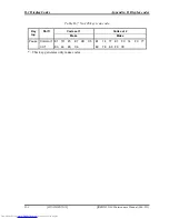
Page 223: ...3 Tests and Diagnostics 3 32 SETUP QOSMIO G20 Maintenance Manual 960 511 CONFIDENTIAL 3 105 ...

Page 224: ...age is displayed Are you sure Y N The changes you made will cause the system to reboot 2 To make other changes press N Repeat the steps above 3 To accept the changes press Y NOTE You can press Esc to quit at any time without saving changes SETUP asks you to confirm that you do not want to save your changes When SETUP is displayed at the next time the current configuration appears The Factory Prese...

Page 225: ...matically calculated by the computer You cannot change this value 2 System Date Time Sets the date and time System Date Sets date System Time Sets time 3 Battery a Battery Save Mode This option is used to select Full Power Low Power or User Setting of the battery save mode When you select the battery save mode the followings will appear Full Power The following shows full power settings Low Power ...

Page 226: ...ower Mode CPU Sleep Mode Use this option to enable or disable the CPU sleep function Enabled Enables sleep mode Default Disabled Disables sleep mode LCD Brightness Use this option to set the level of LCD brightness Super Bright Full brightness for maximum visibility Bright Full brightness for high visibility Semi Bright Less than full brightness for saving power Cooling Method Maximum Performance ...

Page 227: ...ess devices are not used while battery operation Default Disabled Disable the Power saving function and drive with maximum performance Enabled PCI Express devices are not used 4 Password This option sets or resets the user password for power on and instant security Fn F1 Registered The user password has been registered Not registered The user password has not been registered For details on setting...

Page 228: ...bootable files in the following order CD ROM LAN FDD and HDD HDD FDD CD ROM LAN The computer looks for bootable files in the following order HDD FDD CD ROM and LAN Default 1 CD ROM refers to a Optical Disk Drive b HDD Priority Use this option to set the booting priority from HDD Built in HDD1 Built in HDD2 Default detecting boot command from Built in HDD1 Built in HDD2 Built in HDD1 detecting boot...

Page 229: ...rom the followings Dynamically Switchable Enables Pentium M processor featuring Intel SpeedStep technology Default Always High Disables Pentium M processor featuring Intel SpeedStep technology and always runs the processor at its maximum speed Always Low Disables Pentium M processor featuring Intel SpeedStep technology and always runs the processor at its default speed d Execute Disable Bit Capabi...

Page 230: ...r the Alarm Date Option set the date to turn on the power automatically When it is set to Disabled the time to turn on automatically is not set NOTE 1 Do not remove the AC adaptor and battery pack at the same time when you use this feature If you do so data saved by the resume function will be lost You must also reset this option 2 If you have set a password and the computer boots by the Auto Powe...

Page 231: ...f ys off Beep Volume Medium LED Mode Mode 2 OPTIONS Beep Volume Off No sound Low With Sound Volume small Medium With sound Volume Middle Default High With sound Volume Big LED Mode Mode1 No LED is glowed in normal situation LED is glowed when the button is touched Mode2 All LED is glowed in normal situation LED is turned off when the button is touched Default i Language During Bootup This option s...

Page 232: ...DD 1 This cannot be changed If HDD 1 is not installed No Drive is displayed Built in HDD 2 This cannot be changed If HDD 2 is not installed No Drive is displayed CD ROM This cannot be changed This is not displayed when a drive is not built in 9 PCI Bus This option displays the interrupt level for the Card Bus in the computer It is for information only and cannot be changed PCI BUS IRQ10 IRQ11 10 D...

Page 233: ...screen Enabled Enables the LCD display stretch feature Default Disabled Disables the LCD display stretch feature c TV Type This option allows you to select the type of TV NTSC Japan TV in Japanese system NTSC US TV in the U S system PAL S Video TV in Europe and China system 525p 480p D2 High Definition Television with 480 progressive scan 750p 720p D4 High Definition Television with 720 progressiv...

Page 234: ...d Enabled Enables LEGACY support Default USB floppy disk is available without the driver Disabled Disables LEGACY support 13 PCI LAN This option sets the Enable Disable of the built in LAN functions Enabled Enables built in LAN functions Default Disabled Disables built in LAN functions 14 RAID ARRAY This option sets the RAID configuration a Current State This option indicates current hard disk con...

Page 235: ...the setting of the BIOS setup Built in HDD Sets RAID configuration level of the built in HDD Second HDD Sets RAID configuration level of the second HDD c Execute Creation This option is displayed only when the setting is changed in the Create State Set the cursor bar to Execute Creation and press Space or Back Space The following message will appear Warning If you change RAID array you need to ins...

Page 236: ...3 32 SETUP 3 Tests and Diagnostics 3 118 CONFIDENTIAL QOSMIO G20 Maintenance Manual 960 511 ...

Page 237: ...Chapter 4 Replacement Procedures CONFIDENTIAL ...

Page 238: ...4 Replacement Procedures 4 4 ii CONFIDENTIAL QOSMIO G20 Maintenance Manual 960 511 ...

Page 239: ... 4 3 2 Bridge media 4 12 4 4 HDD 4 13 4 5 MDC 4 17 4 6 Memory module 4 19 4 7 Keyboard 4 21 4 8 Bottom cover assembly 4 24 4 9 LAN jack 4 29 4 10 Speaker L Modem jack 4 30 4 11 AV IN board 4 32 4 12 Battery latch assembly 4 33 4 13 Optical disk drive 4 35 4 13 1 Replacing the optical disk drive 4 35 4 13 2 Ejecting the optical disk 4 37 4 14 SJ board Internal Microphone 4 39 4 14 1 SJ board 4 39 4...

Page 240: ...a board 4 60 4 26 System board 4 61 4 27 PC card slot 4 63 4 28 Bluetooth module 4 65 4 29 Volume sensor board 4 67 4 30 Touch sensor board 4 68 4 31 Touch pad 4 70 4 32 Latch assembly 4 72 4 33 LCD unit FL inverter 4 74 4 34 LCD harness 4 79 4 35 Wireless antennas 4 82 4 36 Display latch hook 4 85 4 37 Display rear cover 4 86 4 38 Hinge 4 87 4 39 Fluorescent lamp 4 89 4 39 1 Replacing the 17 0 in...

Page 241: ...6 Figure 4 14 Removing the bottom cover assembly 4 26 Figure 4 15 Removing the LAN jack 4 29 Figure 4 16 Removing the speaker L modem jack 4 30 Figure 4 17 Removing the AV IN board 4 32 Figure 4 18 Removing the battery latch assembly 4 33 Figure 4 19 Removing the battery lock and battery latch slider 4 34 Figure 4 20 Removing the ODD assembly 4 35 Figure 4 21 Removing the ODD rear bracket 4 36 Fig...

Page 242: ...e 4 42 Removing the volume sensor board 4 67 Figure 4 43 Removing the touch sensor board 4 68 Figure 4 44 Removing the touch pad 4 70 Figure 4 45 Removing the latch assembly 4 72 Figure 4 46 Removing the LCD mask 4 74 Figure 4 47 Removing the FL inverter 4 75 Figure 4 48 Removing the LCD unit 4 76 Figure 4 49 Removing the LCD support 4 77 Figure 4 50 Removing the hinge rear cap L 4 79 Figure 4 51 ...

Page 243: ...t section numbers in this manual In all cases when removing an FRU the battery pack must also be removed When repairing an FRU that is the potential cause of a computer fault use the chart to determine the order in which FRUs need to be removed The tilt stand if it is installed can be removed without any other FRUs removed Chart Notation The chart shows the case for the following example Removing ...

Page 244: ...eady charged the risk of electric shock remains even when the AC adapter is unplugged from the socket To prevent electric shock always take off any metal jewelry or accessories such as necklaces bracelets or rings before working on the computer Never work with wet or moist hands 3 Take care not to injury yourself on any edges or corners CAUTION 1 Confirm that replacement parts have compatible spec...

Page 245: ...which FRU is the cause of the fault 5 Do not perform any unnecessary work Always work in accordance with the disassembly and reassembly procedures in this manual 6 Keep parts removed from the computer in a safe place away from the computer where they will not be damaged or interfere with your work 7 Disassembling requires the removal of a large number of screws Keep removed screws in a safe place ...

Page 246: ...oth sides of the plate and connector are at the same height and that the cable is fixed in the correct position Pull the cable to ensure that it is securely connected If the cable is disconnected from the connector reconnect it making sure that you lift the pressure plate high enough to insert fully the cable For spring connectors lifting up the stopper frees the cable and allows it to be pulled o...

Page 247: ...ews left over Using an incorrect screw may damage the thread or screw head and result in the FRU not being securely fastened in place After installing FRUs check that the computer operates correctly Tools and Equipment For your safety and the safety of the people around you it is important that you use Electrostatic Discharge ESD equipment Correctly utilizing of the equipment increases the percent...

Page 248: ...gf cm NOTE To prevent damage to THIN HEAD screws press along the axis of the screwdriver while turning the screw This is because the contact area between the screw and driver is less than for a pan head screw standard pan shaped screw head Grip Color Some screws have a colored grip area to help you determine the length of the screw Even numbered length screws Brown G rip a re a Odd numbered length...

Page 249: ...ews including the types and lengths of the screws are indicated on the computer body Format Screw shape Screw length mm Screw shape B Bind screw F Thin head screw S Super thin head screw T Tapping screw U Other screws Unique screws pan head stud etc Example B6 6mm bind screw QOSMIO G20 Maintenance Manual 960 511 CONFIDENTIAL 4 7 ...

Page 250: ... computer 2 Disconnect the AC adapter and all external devices from the computer 3 Turn the computer upside down 4 Release the battery lock 5 Slide the battery latch to the arrow direction and pull up the battery 6 Release the hooks of the battery cover and remove the battery pack from the battery cover Battery cover Hook Battery lock Battery latch Battery pack Figure 4 1 Removing the battery pack...

Page 251: ...with the laws and ordinances of your local authority Use only the batteries approved by Toshiba NOTE Check visually the battery terminals and clean off any dirt with a dry cloth 1 Turn off the power of the computer 2 Disconnect the AC adapter and all external devices from the computer 3 Attach the battery cover to the battery pack 4 Place the battery pack into the slot from the other side of the c...

Page 252: ...s in their manual or the manuals of the computer system you are using 1 Push the eject button It will pop out when you release it Then press the eject button once more to eject an ExpressCard or PC card 2 Grasp an ExpressCard or PC card and remove it NOTE If an ExpressCard or PC card is not inserted all the way the eject button may not pop out Be sure to push an ExpressCard or PC card firmly and p...

Page 253: ...xpressCard or PC card Installing an ExpressCard PC card The following describes the procedure for inserting an ExpressCard PC card See Figure 4 2 1 Make sure the eject button does not stick out 2 Insert an ExpressCard or PC card and press it until it is securely connected QOSMIO G20 Maintenance Manual 960 511 CONFIDENTIAL 4 11 ...

Page 254: ...ns in the each Bridge Media manual or the manuals of the computer system you are using 1 Push a Bridge media It will pop out partly when you release so pull out the card For an instance SD card is described in the figure 4 3 Bridge media SD card Figure 4 3 Removing a bridge media Installing a Bridge media The following describes the procedure for inserting a Bridge Media See Figure 4 3 1 Insert a ...

Page 255: ...upside down 2 Turn the screw with e ring securing an HDD 1 slot cover and remove an HDD 1 slot cover 3 Remove the following screw securing the HDD 1 assembly M2 5x6 0B FLAT BIND screw x1 4 Disconnect the HDD 1 assembly from the connector CN1850 on the system board while sliding along the cutting tab HDD 1 slot cover HDD 1 assembly Screw with e ring M2 5x6 0B FLAT BIND CN1850 Figure 4 4 Removing a ...

Page 256: ...llowing screw securing the HDD 2 assembly M2 5x6 0B FLAT BIND screw x1 7 Disconnect the HDD 2 assembly from the connector CN1860 on the system board by sliding it toward the arrow pointed HDD 2 slot cover Screw with e ring M2 5x6 0B FLAT BIND HDD 2 slot assembly CN1860 Figure 4 5 Removing the HDD 2 assembly 4 14 CONFIDENTIAL QOSMIO G20 Maintenance Manual 960 511 ...

Page 257: ...he following screws securing the HDD holder and remove the HDD holder from HDD M3 0x4 0Z FLAT BIND screw x4 M3 0x4 0Z FLAT BIND M3 0x4 0Z FLAT BIND HDD holder HDD Figure 4 6 Removing a HDD QOSMIO G20 Maintenance Manual 960 511 CONFIDENTIAL 4 15 ...

Page 258: ... 2 slot from the screw hole side first and connect it carefully to the CN1860 on the system board 3 Secure the HDD 2 assembly with the following screw M2 5x6 0B FLAT BIND screw x1 4 Install the HDD 2 slot cover and secure it with the screw with e ring 5 Insert the HDD 1 assembly into the HDD slot while sliding along the cutting tab and connect it carefully to the CN1850 on the system board 6 Secur...

Page 259: ...he insulator remove the following screws securing a MDC M2 0x4 0C BIND screw x2 2 Pull a MDC straight up and disconnect the MDC from the connector CN3000 on the SD board 3 Disconnect the RJ11 harness from the MDC M2 0x4 0C BIND Insulator MDC RJ11 harness CN3000 Figure 4 7 Removing a MDC QOSMIO G20 Maintenance Manual 960 511 CONFIDENTIAL 4 17 ...

Page 260: ...re for installing a MDC See Figure 4 7 1 Connect the RJ11 harness to the connector of the MDC 2 Install a MDC and connect it to the connector CN3000 on the SD board 3 Secure the MDC with the following screws M2 0x4 0C BIND screw x2 4 18 CONFIDENTIAL QOSMIO G20 Maintenance Manual 960 511 ...

Page 261: ...ause memory access problems Never press hard or bend a memory module Removing a memory module To remove a memory module confirm that the computer is in boot mode Then perform the following procedure See Figure 4 8 1 Turn the screw with e ring securing the memory slot cover 2 Remove the memory slot cover 3 Open the left and right latches and remove a memory module Memory module Screw with e ring Me...

Page 262: ...to slot A CN1400 The computer does not boot when slot A is vacant After installing the memory module confirm that the memory module is fixed with the left and right latches Never press hard or bend a memory module 2 Install the memory slot cover and secure it with the screw with e ring 3 When the power of the computer is turned on the computer checks automatically the memory size Confirm that the ...

Page 263: ...lay 2 Insert your finger into the slot between the keyboard brace and the computer Then lift up the keyboard brace to unlatch and remove it 3 Remove the following screw securing the keyboard hold plate M2 0x4 0C BIND screw x1 4 Remove the following screws securing the keyboard M2 5x4 0B FLAT BIND screw x2 Keyboard brace Keyboard hold plate M2 0x4 0C BIND M2 5x4 0B FLAT BIND M2 5x4 0B FLAT BIND Fig...

Page 264: ...he keyboard support plate and remove the keyboard support plate M2 5x8 0B FLAT BIND screw x2 7 Disconnect the keyboard cable from the connector CN3200 on the system board 8 Remove the keyboard M2 5x8 0B FLAT BIND Keyboard support plate Keyboard cable Keyboard CN3200 Figure 4 10 Removing the keyboard 4 22 CONFIDENTIAL QOSMIO G20 Maintenance Manual 960 511 ...

Page 265: ...the keyboard support plate and secure it with the following screws M2 5x8 0B FLAT BIND screw x2 3 Turn the keyboard face up and put it on the computer Make sure that there is no space between the keyboard and the computer 4 Secure the keyboard with the following screws M2 5x4 0B FLAT BIND screw x2 5 Install the keyboard hold plate and secure it with the following screw M2 0x4 0C BIND screw x1 6 In...

Page 266: ...ble from the connector CN3201 5 Disconnect the Volume harness from the connector CN3330 6 Disconnect the Bluetooth flat cable from the connector CN4400 7 Disconnect the Touch sensor flat cable from the connector CN3360 8 Remove the following screws securing the cover assembly M2 5x8 0B FLAT BIND screw x5 Figure 4 11 Removing the screws from cover assembly M2 5x4 0B FLAT BIND LCD harness cover M2 5...

Page 267: ...AV IN harness CN5660 CN6002 Speaker cable R Figure 4 12 Disconnecting the cables 12 Remove the following screws securing the bottom cover assembly M2 0x4 0B BIND screw x1 Described as 4 or LH or in the figure M2 0x4 0B LH STICK screw x1 M2 5x6 0B FLAT BIND screw x3 Described as 6 in the figure M2 5x8 0B FLAT BIND screw x9 Described as 8 in the figure M2 5x16 0B FLAT BIND screw x6 Described as 16 i...

Page 268: ...8 8 8 6 16 Figure 4 13 Removing the screws from bottom cover assembly 13 Pulling out the RJ45 harness from the slot remove the bottom cover assembly Bottom cover assembly RJ45 harness Slot Figure 4 14 Removing the bottom cover assembly 4 26 CONFIDENTIAL QOSMIO G20 Maintenance Manual 960 511 ...

Page 269: ...5x6 0B FLAT BIND screw x3 Described as 6 in the figure M2 5x8 0B FLAT BIND screw x9 Described as 8 in the figure M2 5x16 0B FLAT BIND screw x6 Described as 16 in the figure 3 Connect the AV IN harness to the connector CN5660 in the memory module slot 4 Connect the speaker cable L to the connector CN6002 under the insulator of HDD 2 slot 5 Turn the computer right side up 6 Secure the cover assembly...

Page 270: ...t Procedures 4 28 CONFIDENTIAL QOSMIO G20 Maintenance Manual 960 511 12 Connect the LCD harness to the connector CN5000 on the system board 13 Install the LCD harness cover and secure it with the following screw M2 5x4 0B FLAT BIND screw x1 ...

Page 271: ...e 4 15 1 Pull up and remove the LAN jack from the bottom cover assembly LAN jack Figure 4 15 Removing the LAN jack Installing the LAN jack The following describes the procedure for installing the LAN jack See Figure 4 15 1 Install the LAN jack by sliding it to the slot of bottom cover assembly QOSMIO G20 Maintenance Manual 960 511 CONFIDENTIAL 4 29 ...

Page 272: ...ide of bottom cover assembly disconnect the AV IN harness from the connector CN9614 on the AV IN board 2 Releasing the wound speaker L cable from the guide of bottom cover assembly remove the speaker L from the slot 3 Pull up and remove the Modem jack from the slot of bottom cover assembly Guide Modem jack Speaker L Guide AV IN harness CN9614 Figure 4 16 Removing the speaker L modem jack 4 30 CONF...

Page 273: ... modem jack See Figure 4 16 1 Install the modem jack to the bottom cover assembly 2 Wind the speaker L cable to the guide of bottom cove assembly and install the speaker L in the slot 3 Connect the AV IN harness to the connector CN9614 on the AV IN board and arrange the harness along the guides QOSMIO G20 Maintenance Manual 960 511 CONFIDENTIAL 4 31 ...

Page 274: ... FLAT BIND screw x1 2 Remove AV IN board from the bottom cover assembly M2 5x4 0B FLAT BIND AV IN board Figure 4 17 Removing the AV IN board Installing the AV IN board The following describes the procedure for installing the AV IN board See Figure 4 17 1 Install the AV IN board to the bottom cover assembly and secure it with the following screw M2 5x4 0B FLAT BIND screw x1 4 32 CONFIDENTIAL QOSMIO...

Page 275: ...e battery latch assembly See Figure 4 18 and 4 19 1 Remove the following screws securing the battery latch assembly M2 5x4 0B S THIN FLAT BIND screw x1 2 Remove the battery latch assembly from the bottom cover assembly M2 0x4 0B S THIN FLAT BIND Battery latch assembly Figure 4 18 Removing the battery latch assembly QOSMIO G20 Maintenance Manual 960 511 CONFIDENTIAL 4 33 ...

Page 276: ...ch slider Installing the battery latch assembly The following describes the procedure for installing the battery latch assembly See Figure 4 18 and 4 19 1 Assemble the spring and battery latch slider to the battery latch base while hooking the tab 2 Install the battery lock to the battery latch assembly 3 Install the battery latch assembly to the bottom cover assembly and secure it with the follow...

Page 277: ...l disk drive The following describes the procedure for removing the optical disk drive See Figure 4 20 and 4 21 1 Remove the following screw securing the ODD assembly M2 5x4 0B FLAT BIND screw x1 2 Disconnect the ODD flat cable from the connector CN9680 on the ODD relay board 3 Remove the ODD assembly ODD assembly M2 5x4 0B FLAT BIND CN9680 ODD flat cable Figure 4 20 Removing the ODD assembly QOSM...

Page 278: ... 4 21 Removing the ODD rear bracket Installing the optical disk drive The following describes the procedure for installing the optical disk drive See Figure 4 20 and 4 21 1 Installing the ODD relay board and ODD rear bracket to the optical disk drive secure them with the following screws M2 0x4 0B S THIN FLAT BIND screw x2 2 Installing the ODD side bracket to the optical disk drive secure it with ...

Page 279: ... ejecting the optical disk from the optical disk drive See Figure 4 22 1 Remove the following screws securing the ODD cover M1 8x2 0C S THIN FLAT BIND screw x4 2 Remove the ODD cover from the ODD base assembly by opening it toward the arrow pointed 3 Hold the optical disk and lift it out M1 8x2 0C S THIN FLAT BIND ODD cover Hook Slot M1 8x2 0C S THIN FLAT BIND Optical disk ODD base assembly Figure...

Page 280: ...r assembling the ODD assembly from the optical disk drive See Figure 4 22 1 Install the ODD cover to the ODD base assembly by sliding the hook into the slot of ODD base assembly 2 Secure the ODD cover with the following screws M1 8x2 0C S THIN FLAT BIND screw x4 4 38 CONFIDENTIAL QOSMIO G20 Maintenance Manual 960 511 ...

Page 281: ...he connector CN6000 on the SJ board 3 Remove the following screw and pull out the SJ board from the cover assembly by extracting jacks from the jack holes M2 5x4 0B FLAT BIND screw x1 4 Turning over the SJ board disconnect the sound jack flat cable from the connector CN9530 and the USB harness from the connector CN4622 on the SJ board CN9530 CN4622 SJ board Sound jack flat cable CN9520 M2 5x4 0B F...

Page 282: ...e USB harness to the connector CN4622 on the SJ board 2 Install the SJ board to the cover assembly by sliding jacks into the jack holes of cover assembly and secure it with the following screw M2 5x4 0B FLAT BIND screw x1 3 Connect the internal microphone cable to the connector CN6000 on the SJ board 4 Connect the sound jack flat cable to the connector CN9520 on the SD board 4 40 CONFIDENTIAL QOSM...

Page 283: ...x4 0B FLAT BIND screw x1 2 Pull out the internal microphone from the mic holder M2 5x4 0B FLAT BIND Internal microphone Mic holder Figure 4 24 Removing the internal microphone Installing the Internal microphone The following describes the procedure for installing the internal microphone See Figure 4 24 1 Install the internal microphone to the mic holder 2 Install the internal microphone assembly a...

Page 284: ...e SD board 2 Disconnect the Power SW harness from the connector CN9521 on the SD board 3 Turning up the insulator remove the following screws securing the SD board and remove the SD board from the cover assembly M2 5x3 0S FLAT BIND screw x3 Power SW harness Sound harness M2 5x3 0S FLAT BIND CN9510 Sound board CN9521 M2 5x3 0S FLAT BIND Figure 4 25 Removing the sound board 4 42 CONFIDENTIAL QOSMIO ...

Page 285: ... the sound board See Figure 4 25 1 Install the sound board and secure it with the following screws M2 5x3 0S FLAT BIND screw x3 2 Connect the Power SW harness to the connector CN9521 on the SD board 3 Connect the Sound harness to the connector CN9510 on the SD board QOSMIO G20 Maintenance Manual 960 511 CONFIDENTIAL 4 43 ...

Page 286: ...6 1 Remove the following screw securing the power SW board and pull up the Power SW board from the cover assembly M2 5x4 0B FLAT BIND screw x1 2 Disconnect the Power SW harness from the connector CN9622 on the Power SW board M2 5x4 0B FLAT BIND Power SW board Power SW harness CN9622 Figure 4 26 Removing the Power SW board 4 44 CONFIDENTIAL QOSMIO G20 Maintenance Manual 960 511 ...

Page 287: ...cedure for installing the Power SW board See Figure 4 26 1 Connect the Power SW harness to the connector CN9622 on the Power SW board 2 Install the Power SW board to the cover assembly and secure it with the following screw M2 5x4 0B FLAT BIND screw x1 QOSMIO G20 Maintenance Manual 960 511 CONFIDENTIAL 4 45 ...

Page 288: ...lowing screws securing the battery board M2 5x4 0B FLAT BIND screw x2 3 Slightly pulling up the battery board disconnect the battery signal harness from the connector CN9691 and the battery power harness from the connector CN9690 on the battery board 4 Remove the battery board from the cover assembly M2 5x4 0B FLAT BIND Battery signal harness RTC battery cable CN9990 Battery board M2 5x4 0B FLAT B...

Page 289: ...ct the battery power harness to the connector CN9690 and the battery signal harness to the connector CN9691 on the battery board 2 Install the battery board to the cover assembly and secure it with the following screws M2 5x4 0B FLAT BIND screw x2 3 Connect the RTC battery cable to the connector CN9990 on the battery board QOSMIO G20 Maintenance Manual 960 511 CONFIDENTIAL 4 47 ...

Page 290: ...igure 4 28 1 Turning up the insulator pull out the RTC battery from the insulator RTC battery Insulator Figure 4 28 Removing the RTC battery Installing the RTC battery The following describes the procedure for installing the RTC battery See Figure 4 28 1 Turning up the insulator set the RTC battery into the insulator 4 48 CONFIDENTIAL QOSMIO G20 Maintenance Manual 960 511 ...

Page 291: ...om the connector CN 2200 of mini PCI slot CN2200 Wireless LAN card Wireless LAN antenna cables Figure 4 29 Removing the wireless LAN card Installing the wireless LAN card The following describes the procedure for installing the wireless LAN card See Figure 4 29 1 Insert a wireless LAN card into the connector CN2200 of the mini PCI slot slantwise and press it to connect firmly 2 Connect the wireles...

Page 292: ...connect the TV tuner harness from the connector PJ621 on the TV tuner module and CN5661 on the system board 3 Remove the following screws securing the TV tuner module M2 0x4 0C BIND screw x2 4 Open the left and right latches and remove the TV tuner module from the connector CN 2220 of mini PCI slot M2 0x4 0C BIND CN2220 TV antenna harness CN5661 TV tuner harness PJ621 PJ601 Figure 4 30 Removing th...

Page 293: ...he connector CN2220 of the mini PCI slot slantwise and press it to connect firmly 2 Secure the TV tuner module with the following screws M2 0x4 0C BIND screw x2 3 Connect the TV tuner harness to the connector PJ621 on the TV tuner module and CN5661 on the system board 4 Connect the TV antenna harness to the connector PJ601 on the TV tuner module QOSMIO G20 Maintenance Manual 960 511 CONFIDENTIAL 4...

Page 294: ...d remove the CPU fan M2 5x4 0B FLAT BIND screw x2 Hook M2 5x4 0B FLAT BIND CN8770 Figure 4 31 Removing the CPU fan Installing the CPU fan The following describes the procedure for installing the CPU Fan See Figure 4 31 1 Arranging the CPU fan cable through the hook connect the CPU fan cable to the connector CN8770 on the system board 2 Install the CPU fan and secure it with the following screws M2...

Page 295: ... 33 1 Remove the following screws securing the CPU holder M2 0x4 0C BIND screw x3 NOTE When removing the CPU holder be sure to remove the screws in the reverse order of the number marked on the holder 2 Remove the CPU holder and CPU fin CPU holder M2 0x4 0C BIND M2 0x4 0C BIND CPU fin Figure 4 32 Removing the CPU fin QOSMIO G20 Maintenance Manual 960 511 CONFIDENTIAL 4 53 ...

Page 296: ...stalling the CPU fin CPU See Figure 4 32 to 4 34 1 Check that the mark of cam is in the unlocking position 2 Attach the CPU to the correct position in the CPU socket 3 Fix the CPU by rotating the cam 180 degrees to the clockwise with a flat blade screwdriver 4 If there is already silicon grease on the CPU clean it with a cloth Using a special applicator apply silicon grease so that the CPU chip on...

Page 297: ...ial applicator Figure 4 34 Applying silicon grease 5 Install the CPU fin and CPU holder and secure them with the following screws M2 0x4 0C BIND screw x3 NOTE When securing the CPU holder be sure to secure the screws in the order of the number marked on the holder QOSMIO G20 Maintenance Manual 960 511 CONFIDENTIAL 4 55 ...

Page 298: ...m the connector CN8780 on the system board 2 Remove the following screws securing the VGA fan and remove the VGA fan M2 5x4 0B FLAT BIND screw x2 3 Remove the following screws securing the VGA fin and remove the VGA fin M2 0x3 0S S THIN FLAT BIND screw x2 Glass tape M2 5x4 0B FLAT BIND M2 5x4 0B FLAT BIND VGA fan M2 0x3 0S S THIN FLAT BIND VGA fin CN8780 Figure 4 35 Removing the VGA fin 4 56 CONFI...

Page 299: ... applying the silicon grease refer to Installing the CPU 2 Secure the VGA fin with the following screws M2 0x3 0S S THIN FLAT BIND screw x2 3 Install the VGA fan and secure it with the following screws M2 5x4 0B FLAT BIND screw x2 4 Connect the VGA fan cable to the connector CN8780 on the system board and stick the glass tape to fix the VGA fan cable QOSMIO G20 Maintenance Manual 960 511 CONFIDENT...

Page 300: ...Remove the GMCH heat sink M2 0x3 0S S THIN FLAT BIND GMCH heat sink Figure 4 36 Removing the GMCH heat sink Installing the GMCH heat sink The following describes the procedure for installing the GMCH heat sink See Figure 4 36 1 Install the GMCH heat sink NOTE For details on applying the silicon grease refer to Installing the CPU 2 Secure the GMCH heat sink with the following screws M2 0x3 0S S THI...

Page 301: ... speaker R cable from the connector CN6003 on the system board Speaker R Speaker R cable DC IN jack CN6003 Figure 4 37 Removing the speaker R Installing the speaker R The following describes the procedure for installing the speaker R See Figure 4 37 1 Connect the speaker R cable to the connector CN6003 on the system board 2 Set the speaker R in the slot of cover assembly 3 Install the DC IN jack a...

Page 302: ...V antenna harness from the connector CN9611 on the TV antenna board M2 5x4 0B FLAT BIND CN9611 TV antenna harness Figure 4 38 Removing the TV antenna board Installing the TV antenna board The following describes the procedure for installing the TV antenna board See Figure 4 38 1 Connect the TV antenna harness to the connector CN9611 on the TV antenna board 2 Install the TV antenna board to the cov...

Page 303: ...procedure for removing the system board See Figure 4 39 1 Pull up and remove the system board from the cover assembly 2 Disconnect the battery power harness from the connector CN8020 3 Disconnect the battery signal harness from the connector CN8811 4 Disconnect the SD board flat cable from the connector CN9500 5 Disconnect the ODD flat cable from the connector CN1810 6 Disconnect the USB harness f...

Page 304: ...ODD flat cable to the connector CN1810 3 Connect the SD board flat cable to the connector CN9500 4 Connect the battery signal harness to the connector CN8811 5 Connect the battery power harness to the connector CN8020 6 Install the system board to the cover assembly NOTE Confirm that volume harness is arranged in the right position while installing the system board 4 62 CONFIDENTIAL QOSMIO G20 Mai...

Page 305: ...40 1 Remove the following screws securing the PC card slot M2 0x3 0B S THIN FLAT BIND screw x2 M2 0x8 0B BIND screw x2 2 Pull up the PC card slot straight and remove it from the connector CN2110 on the system board PC card slot CN2110 M2 0x8 0B BIND M2 0x3 0B S THIN FLAT BIND Figure 4 40 Removing the PC card slot QOSMIO G20 Maintenance Manual 960 511 CONFIDENTIAL 4 63 ...

Page 306: ...ling the PC card slot The following describes the procedure for installing the PC card slot See Figure 4 40 1 Insert the terminal of the PC card slot into the connector CN2110 on the system board 2 Secure the PC card slot with the following screws M2 0x3 0B S THIN FLAT BIND screw x2 M2 0x8 0B BIND screw x2 ...

Page 307: ...able from the connector on the bluetooth module 2 Disconnect the bluetooth flat cable from the connector on the bluetooth module 3 Remove the following screw securing the bluetooth module and remove the bluetooth module M2 0x3 0C S THIN FLAT BIND screw x1 M2 0x3 0C S THIN FLAT BIND Bluetooth flat cable Bluetooth module Insulator Bluetooth antenna cable Figure 4 41 Removing the bluetooth module QOS...

Page 308: ...1 Install the bluetooth module and secure it with the following screw M2 0x3 0C S THIN FLAT BIND screw x1 2 Connect the bluetooth flat cable to the connector on the bluetooth module 3 Connect the bluetooth antenna cable from the connector on the bluetooth module 4 Cover the bluetooth module slot with the insulator 4 66 CONFIDENTIAL QOSMIO G20 Maintenance Manual 960 511 ...

Page 309: ...over assembly and remove the volume sensor board from the cover assembly Volume sensor holder Volume sensor board M2 5x2 8B FLAT BIND Volume harness Figure 4 42 Removing the volume sensor board Installing the volume sensor board The following describes the procedure for installing the volume sensor board See Figure 4 42 1 Arranging the volume harness along the guide of cover assembly install the v...

Page 310: ...llowing screws securing the touch sensor plate and remove the touch sensor plate M2 5x4 0B FLAT BIND screw x9 3 Pull up and remove the touch sensor board from the cover assembly CAUTION The removed touch sensor board is not reusable Therefore when installing the touch sensor board it must be a new one M2 5x4 0B FLAT BIND M2 5x4 0B FLAT BIND Touch sensor flat cable Touch sensor plate Touch sensor b...

Page 311: ...ew one 2 It is possible to stick a new touch sensor board over the double sided tape remained on the cover assembly 3 Only three times can be acceptable for sticking the touch sensor panel on the cover assembly The remained tapes on the cover assembly can keep its adhesion within three ply stacked tapes If exceeding the acceptable times it is also necessary to replace the cover assembly 2 Install ...

Page 312: ...le from the connector on the touch pad 2 Remove the following screws securing the touch pad plate M2 0x4 0C BIND screw x3 3 Turning up the insulator remove the touch pad plate 4 Peel off and remove the touch pad from the cover assembly Touch pad flat cable Insulator Glass tape Touch pad plate M2 0x4 0C BIND Touch pad M2 0x4 0C BIND Figure 4 44 Removing the touch pad 4 70 CONFIDENTIAL QOSMIO G20 Ma...

Page 313: ...a new touch pad When installing the touch pad be careful not to get the bubbles under the touch pad 2 Stick and install the touch pad on the cover assembly 3 Install the touch pad plate and secure it with the following screws M2 0x4 0C BIND screw x3 NOTE When securing the touch pad with the screws confirm the following position 4 Connect the touch pad flat cable to the connector on the touch pad a...

Page 314: ...e Figure 4 45 1 Remove the following screws securing the latch assembly M2 5x4 0B FLAT BIND screw x2 2 Pull up and remove the latch assembly 3 Releasing hooks of latch assembly disassemble the latch slider and spring M2 5x4 0B FLAT BIND Latch assembly Latch slider Spring Figure 4 45 Removing the latch assembly 4 72 CONFIDENTIAL QOSMIO G20 Maintenance Manual 960 511 ...

Page 315: ... installing the latch assembly See Figure 4 45 1 Assembling the spring and latch slider fit the hooks of latch slider into the latch assembly 2 Install the latch assembly to the cover assembly and secure it with the following screws M2 5x4 0B FLAT BIND screw x2 QOSMIO G20 Maintenance Manual 960 511 CONFIDENTIAL 4 73 ...

Page 316: ... FL inverter See Figure 4 46 to 4 49 1 Removing the mask seal and mask pad remove the following screws securing the LCD mask M2 5x8 0B FLAT BIND screw x4 M2 5x6 0C S THIN FLAT BIND screw x2 2 Insert your finger between the edge of the LCD mask and the display rear cover and remove the LCD mask while releasing the latches M2 5x8 0B FLAT BIND with mask seal M2 5x6 0C S THIN FLAT BIND with mask pad M...

Page 317: ...ter 5 Disconnect the LCD harnesses from the connectors CN1 and CN2 on the FL inverter 6 Disconnect the HV harnesses from the connectors CN3 and CN4 on the FL inverter 7 Remove the FL inverter from the display assembly CN2 CN1 FL inverter M2 0x4 0C BIND Insulator LCD harness HV harness Figure 4 47 Removing the FL inverter QOSMIO G20 Maintenance Manual 960 511 CONFIDENTIAL 4 75 ...

Page 318: ... edge of the LCD unit on the display cover lift only the top edge of the LCD unit After peeling off the copper tape disconnect the LCD harness from the connector on the back of the LCD 10 Remove the LCD unit Copper tape LCD harness M2 0x4 0C BIND LCD unit Figure 4 48 Removing the LCD unit 4 76 CONFIDENTIAL QOSMIO G20 Maintenance Manual 960 511 ...

Page 319: ...ng screws securing the LCD support and remove the LCD supports from the LCD unit M2 0x3 0C S THIN FLAT BIND screw x4 LCD support M2 0x3 0C SUPER THIN HEAD M2 0x3 0C SUPER THIN HEAD Figure 4 49 Removing the LCD support QOSMIO G20 Maintenance Manual 960 511 CONFIDENTIAL 4 77 ...

Page 320: ...screw x4 5 Connect LCD harnesses to the connector CN1 and CN2 of the FL inverter CAUTION Be careful not to connect the LCD harnesses to the wrong connectors of FL inverter CN1 smaller one CN2 larger one 6 Connect HV harnesses to the connector CN3 and CN4 of the FL inverter 7 Stick the insulator to the FL inverter 8 Install the FL inverter and secure it with the following screw M2 0x4 0C BIND screw...

Page 321: ...older cover assembly side and remove the LCD harness holder from the cover assembly M2 5x4 0B FLAT BIND screw x1 2 Remove the following screw securing the hinge cap L and remove the hinge rear cap L from the display assembly M2 0x4 0B FLAT BIND screw x1 M2 5x4 0B FLAT BIND LCD harness holder M2 5x4 0B FLAT BIND Hinge rear cap L Figure 4 50 Removing the hinge rear cap L QOSMIO G20 Maintenance Manua...

Page 322: ...r cover side and remove the LCD harness holder from the display rear cover M2 5x4 0B FLAT BIND screw x1 Hinge front cap L M2 5x4 0B FLAT BIND LCD harness holder Figure 4 51 Removing the LCD harness holder 5 Remove the LCD harness from the slot of display assembly LCD harness slot Figure 4 52 Removing the LCD harness 4 80 CONFIDENTIAL QOSMIO G20 Maintenance Manual 960 511 ...

Page 323: ...r display rear cover side to the display rear cover and secure it with the following screw M2 5x4 0B FLAT BIND screw x1 3 Installing the hinge front cap L while hooking the tabs install the hinge rear cap L and secure it with the following screw M2 0x4 0B FLAT BIND screw x1 4 Install the LCD harness holder cover assembly side while holding the LCD harness and secure it with the following screw M2 ...

Page 324: ...re for removing the wireless antennas See Figure 4 53 and 4 54 1 Remove the following screw securing the hinge cap R and remove the hinge rear cap R from the display assembly M2 0x4 0B FLAT BIND screw x1 M2 0x4 0B FLAT BIND Hinge rear cap R Figure 4 53 Removing the hinge rear cap R 4 82 CONFIDENTIAL QOSMIO G20 Maintenance Manual 960 511 ...

Page 325: ...ng off the wireless LAN antennas and bluetooth antenna from the display rear cover remove the wireless antennas from the display assembly Wireless LAN antenna with black cable Acetate tape Hinge front cap R Bluetooth antenna with brown cable Wireless LAN antenna with white cable Figure 4 54 Removing the wireless antennas QOSMIO G20 Maintenance Manual 960 511 CONFIDENTIAL 4 83 ...

Page 326: ... LAN antennas and bluetooth antenna on the display rear cover 2 Arrange the wireless LAN antenna cables and bluetooth antenna cable on the display rear cover and fix them with acetate tapes 3 Installing the hinge front cap R while hooking the tabs install the hinge rear cap R and secure them with the following screw M2 0x4 0B FLAT BIND screw x1 4 84 CONFIDENTIAL QOSMIO G20 Maintenance Manual 960 5...

Page 327: ...HT screw x2 2 Pull up and remove the display latch hook from the display rear cover M2 5x6 0C PSP TIGHT Display latch hook Figure 4 55 Removing the display latch hook Installing the display latch hook The following describes the procedure for installing the display latch hook See Figure 4 55 1 Install the display latch hook to the display rear cover and secure it with the following screws M2 5x6 0...

Page 328: ...ND screw x4 2 Remove the display rear cover from the cover assembly M2 5x4 0B FLAT BIND Display rear cover M2 5x4 0B FLAT BIND Figure 4 56 Removing the display rear cover Installing the display rear cover The following describes the procedure for installing the display rear cover See Figure 4 56 1 Install the display rear cover to the cover assembly and secure it with the following screws M2 5x4 0...

Page 329: ...Remove the following screws securing the hinge L and remove the hinge L M2 5x6 0C PSP TIGHT screw x2 2 Remove the following screws securing the hinge R and remove the hinge R M2 5x6 0B FLAT BIND screw x2 Hinge R M2 5x6 0B FLAT BIND M2 5x6 0C PSP TIGHT Hinge L Figure 4 57 Removing the hinge QOSMIO G20 Maintenance Manual 960 511 CONFIDENTIAL 4 87 ...

Page 330: ...inge The following describes the procedure for installing the hinge See Figure 4 57 1 Install the hinge R to the cover assembly and secure it with the following screws M2 5x6 0B FLAT BIND screw x2 2 Install the hinge L to the cover assembly and secure it with the following screws M2 5x6 0C PSP TIGHT screw x2 ...

Page 331: ...Appendices CONFIDENTIAL ...

Page 332: ...App ii CONFIDENTIAL QOSMIO G20 Maintenance Manual 960 511 ...

Page 333: ...ctor 0 200 pin C 1 C 2 CN1400 Memory connector 1 200 pin C 4 C 3 CN1850 1st HDD I F connector 22 pin C 7 C 4 CN1860 2nd HDD I F connector 22 pin C 7 C 5 CN2100 PC card I F connector 150 pin C 8 C 6 CN3200 Keyboard I F connector 34 pin C 11 C 7 CN3201 Touch pad I F connector 4 pin C 11 C 8 CN8770 CPU FAN connector 3 pin C 12 C 9 CN8780 VGA FAN connector 3 pin C 12 C 10 CN4610 USB I F connector Port...

Page 334: ... C 22 C 27 CN5661 TV tuner I F connector 12 pin C 22 C 28 CN5800 SVP Host I F connector 2 pin C 22 C 29 CN8020 Battery Power I F connector 6 pin C 23 C 30 CN8811 Battery Signal I F connector 15 pin C 23 C 31 CN1810 ODD relay board FNN2D I F connector 50 pin C 24 C 32 CN9500 Sound board FNN2N I F connector 57 pin C 25 C 33 CN5660 AV IN board FNN2V I F connector 10 pin C 26 ODD relay board FNN2D C 3...

Page 335: ... 34 C 50 J6001 External microphone I F connector 6 pin C 35 C 51 DS6000 Headphone SPDIF connector 10 pin C 35 C 52 CN9530 Sound board FNN2N I F connector 20 pin C 35 Battery board FNN2B C 53 CN9690 System board Power I F connector 6 pin C 36 C 54 CN9691 System board Signal I F connector 15 pin C 36 C 55 CN8810 Battery I F connector 10 pin C 36 C 56 CN9990 RTC battery connector 3 pin C 37 Power swi...

Page 336: ...rite Procedures G 1 Appendix H EC KBC Rewrite Procedures H 1 Appendix I Reliability I 1 Appendix J Maintenance of TOSHIBA RAID J 1 J 1 Outline of Maintenance Repair of TOSHIBA RAID J 1 J 2 Analysis and handling by Drive Log J 2 J 3 Operation of Independent utility J 8 App vi CONFIDENTIAL QOSMIO G20 Maintenance Manual 960 511 ...

Page 337: ...ard layout B 10 Figure B 9 TV antenna board layout B 11 Figure E 1 US Keyboard layout E 1 Figure E 2 UK Keyboard layout E 1 Figure F 1 RGB Monitor ID Wraparound connector 15PIN to 15PIN F 1 Figure F 2 LAN loopback connector F 1 Figure J 1 Flowchart of repairing TOSHIBA RAID J 1 Figure J 2 Flowchart of Analysis and handling by Drive Log J 2 Figure J 3 Drive Log J 8 Figure J 4 Tree of menu of Indepe...

Page 338: ...I F connector 150 pin C 8 Table C 6 Keyboard I F connector 34 pin C 11 Table C 7 Touch pad I F connector 4 pin C 11 Table C 8 CPU FAN connector 3 pin C 12 Table C 9 VGA FAN connector 3 pin C 12 Table C 10 USB I F connector Port 0 Port 2 8 pin C 12 Table C 11 USB I F connector Port 1 8 pin C 12 Table C 12 DC IN connector 4 pin C 13 Table C 13 MEDIA BRIDGE I F connector 42 pin C 13 Table C 14 Wirele...

Page 339: ...pin C 25 Table C 33 AV IN board FNN2V I F connector 10 pin C 26 ODD relay board FNN2D Table C 34 CD ROM I F connector 50 pin C 27 Table C 35 System board I F connector 50 pin C 28 Sound board FNN2N Table C 36 MDC I F connector 30 pin C 29 Table C 37 Speaker Left connector 3 pin C 29 Table C 38 System board I F connector 57 pin C 30 Table C 39 Sound jack board I F connector 20 pin C 31 Table C 40 S...

Page 340: ...connector 10 pin C 36 Table C 56 RTC battery connector 3 pin C 37 Power switch board FNN2P Table C 57 Sound board FNN2N I F connector 4 pin C 38 Table D 1 Display codes set 1 to set 2 D 1 Table D 2 Scan codes with left shift key D 5 Table D 3 Scan codes with Numlock mode D 6 Table D 4 Scan codes with Fn key D 6 Table D 5 Scan codes in overlay mode D 7 Table D 6 No 124 key scan code D 7 Table D 7 N...

Page 341: ...FIDENTIAL App xi Table J 7 Items set in View Drive Info J 23 Table J 8 Function of option and key J 24 Table J 9 Content of Drive Log display J 26 Table J 10 Content of View Drive Log menu J 27 Table J 11 Function of key in View Drive Log J 27 ...

Page 342: ... sure to seat it so that it is properly aligned and maximum visibility of the display is maintained 2 Be careful to align the holes at the four corners of the LCD module with the corresponding holes in the LCD cover before securing the module with screws Do not force the module into place because stress can affect its performance Also the panel s polarized surface is easily scarred so be careful w...

Page 343: ...pe it again If the surface is very dirty we recommend a CRT cleaning agent Apply the agent to a cloth and then wipe the panel s surface Do not apply cleanser directly to the panel 4 If water or other liquid is left on the panel s surface for a long period it can change the screen s tint or stain it Be sure to quickly wipe off any liquid A 2 CONFIDENTIAL QOSMIO G20 Maintenance Manual 960 511 ...

Page 344: ...op it or let it strike a hard object which could cause breakage or cracks 6 CMOS LSI circuits are used in the module so guard against damage from electrostatic discharge Be sure to wear a wrist or ankle ground when handling the module QOSMIO G20 Maintenance Manual 960 511 CONFIDENTIAL A 3 ...

Page 345: ...rays for long periods 8 Do not store the module at temperatures below specifications Cold can cause the liquid crystals to freeze lose their elasticity or otherwise suffer damage 9 Do not disassemble the LCD module Disassembly can cause malfunctions A 4 CONFIDENTIAL QOSMIO G20 Maintenance Manual 960 511 ...

Page 346: ...ou transport the module do not use packing material that contains epoxy resin amine or silicon glue alcohol or oxide These materials can release gas that can damage the panel s polarization QOSMIO G20 Maintenance Manual 960 511 CONFIDENTIAL A 5 ...

Page 347: ...Appendix A Handling the LCD Module A 6 CONFIDENTIAL QOSMIO G20 Maintenance Manual 960 511 ...

Page 348: ...Appendix B Appendix B Board Layout B 1 System Board Front View a l k j i h g f e b c d n m Figure B 1 System board layout front QOSMIO G20 Maintenance Manual 960 511 CONFIDENTIAL B 1 ...

Page 349: ...or cable connector e CN3360 Touch sensor FFC connector f CN8020 Battery power harness connector g CN3201 Touch pad FFC connector h CN8811 Battery signal harness connector i CN3200 Keyboard I F connector j CN9500 Sound FFC I F connector k CN1810 ODD relay board I F connector l CN4611 USB harness connector m CN5000 LCD harness connector n CN4100 RJ45 harness connector B 2 CONFIDENTIAL QOSMIO G20 Mai...

Page 350: ...endix B Board Layout B 2 System Board Back View B 2 System Board Back View a b c t r s d q e f p o n g m h l k j i Figure B 2 System board layout Back QOSMIO G20 Maintenance Manual 960 511 CONFIDENTIAL B 3 ...

Page 351: ...CN5661 TV tuner harness connector g CN2220 TV tuner module I F connector h CN2110 PC card I F connector i CN2200 Wireless LAN card I F connector j CN4200 i LINK IEEE1394 port k CN6003 Speaker R cable connector l CN8800 DC IN jack connector m CN8770 CPU fan cable connector n CN5501 S VIDEO OUT I F port o IS1050 CPU p CN5502 D terminal port q CN5080 RGB I F connector r CN4610 USB port 0 USB port 2 s...

Page 352: ...d b Figure B 3 BT board layout Table B 3 BT board connectors Mark Number Name a CN9690 Battery power harness connector b CN9691 Battery signal harness connector c CN8810 Battery I F connector c CN9990 RTC battery I F connector QOSMIO G20 Maintenance Manual 960 511 CONFIDENTIAL B 5 ...

Page 353: ...igure B 4 SD board layout Table B 4 SD board connectors Mark Number Name a CN3000 MDC I F connector b CN6002 Speaker L cable connector c CN9521 Power SW harness connector d CN9520 Sound jack FFC connector e CN9510 Sound FFC connector B 6 CONFIDENTIAL QOSMIO G20 Maintenance Manual 960 511 ...

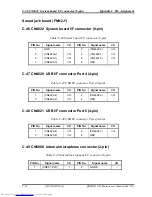
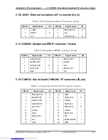
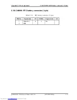
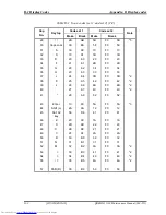
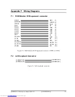
Page 354: ...Appendix B Board Layout B 4 SD board QOSMIO G20 Maintenance Manual 960 511 CONFIDENTIAL B 7 ...

Page 355: ...layout Table B 5 SJ board connectors Mark Number Name a CN4620 USB harness connector b CN9530 Sound jack FFC connector c CN4621 USB port 6 d CN4620 USB port 4 e J600 External microphone jack f D5600 Headphone jack g CN4621 Internal microphone I F connector B 8 CONFIDENTIAL QOSMIO G20 Maintenance Manual 960 511 ...

Page 356: ...d Front layout a b c Back layout Figure B 6 AV IN board layout Table B 6 AV IN board connectors Mark Number Name a J9612 Monitor IN I F port b J9613 S VIDEO IN I F port c CN9613 AV IN harness connector QOSMIO G20 Maintenance Manual 960 511 CONFIDENTIAL B 9 ...

Page 357: ...Power SW board Front layout b a Back layout Figure B 7 Power SW board layout Table B 7 Power SW board connectors Mark Number Name a CN9622 Power SW harness connector b S3310 Power switch button B 10 CONFIDENTIAL QOSMIO G20 Maintenance Manual 960 511 ...

Page 358: ...DD relay board Front layout a Back layout b Figure B 8 ODD relay board layout Table B 8 ODD relay board connectors Mark Number Name a CN9680 ODD I F connector b CN1820 ODD relay FFC I F connector QOSMIO G20 Maintenance Manual 960 511 CONFIDENTIAL B 11 ...

Page 359: ...nna board Front layout Back layout a b Figure B 9 TV antenna board layout Table B 9 TV antenna board connectors Mark Number Name a J9610 TV antenna cable jack b CN9611 TV antenna coaxial cable connector B 12 CONFIDENTIAL QOSMIO G20 Maintenance Manual 960 511 ...

Page 360: ...Appendix B Board Layout B 9 TV antenna board QOSMIO G20 Maintenance Manual 960 511 CONFIDENTIAL B 13 ...

Page 361: ...P I O 14 BDQ01 B1P I O 15 GND 16 BDQ00 B1P I O 17 BDQ03 B1P I O 18 GND 19 BDQ02 B1P I O 20 BDQ12 B1P I O 21 GND 22 BDQ13 B1P I O 23 BDQ11 B1P I O 24 GND 25 BDQ08 B1P I O 26 BDM0 B1P I 27 GND 28 GND 29 BDQS1 B1N I O 30 MCK3 B1P I 31 BDQS1 B1P I O 32 MCK3 B1N I 33 GND 34 GND 35 BDQ09 B1P I O 36 BDQ15 B1P I O 37 BDQ14 B1P I O 38 BDQ10 B1P I O 39 GND 40 GND 41 GND 42 GND 43 BDQ16 B1P I O 44 BDQ21 B1P ...

Page 362: ...1R8 B1V I 88 1R8 B1V I 89 BMA12 B1P I 90 BMA11 B1P I 91 BMA09 B1P I 92 BMA07 B1P I 93 BMA08 B1P I 94 BMA06 B1P I 95 1R8 B1V I 96 1R8 B1V I 97 BMA05 B1P I 98 BMA04 B1P I 99 BMA03 B1P I 100 BMA02 B1P I 101 BMA01 B1P I 102 BMA00 B1P I 103 1R8 B1V I 104 1R8 B1V I 105 BMA10 B1P I 106 BBS1 B1P I 107 BBS0 B1P I 108 BRAS B1N I 109 BWE B1N I 110 MCS2 B1N I 111 1R8 B1V I 112 1R8 B1V I 113 BCAS B1N I 114 MOD...

Page 363: ...BDQ43 B1P I O 152 BDQ46 B1P I O 153 BDQ42 B1P I O 154 BDQ47 B1P I O 155 GND 156 GND 157 BDQ48 B1P I O 158 BDQ52 B1N I O 159 BDQ54 B1P I O 160 BDQ53 B1N I O 161 GND 162 GND 163 N C 164 MCK4 B1P I 165 GND 166 MCK4 B1N I 167 BDQS6 B1N I O 168 GND 169 BDQS6 B1P I O 170 BDM6 B1P I 171 GND 172 GND 173 BDQ51 B1P I O 174 BDQ50 B1P I O 175 BDQ55 B1P I O 176 BDQ49 B1P I O 177 GND 178 GND 179 BDQ57 B1P I O 1...

Page 364: ...I O 15 GND 16 ADQ07 B1P I O 17 ADQ03 B1P I O 18 GND 19 ADQ06 B1P I O 20 ADQ12 B1P I O 21 GND 22 ADQ13 B1P I O 23 ADQ08 B1P I O 24 GND 25 ADQ09 B1P I O 26 ADM0 B1P I 27 GND 28 GND 29 ADQS1 B1N I O 30 MCK0 B1P I 31 ADQS1 B1P I O 32 MCK0 B1N I 33 GND 34 GND 35 ADQ15 B1P I O 36 ADQ10 B1P I O 37 ADQ14 B1P I O 38 ADQ11 B1P I O 39 GND 40 GND 41 GND 42 GND 43 ADQ16 B1P I O 44 ADQ20 B1P I O 45 ADQ17 B1P I ...

Page 365: ...86 N C 87 1R8 B1V I 88 1R8 B1V I 89 AMA12 B1P I 90 AMA11 B1P I 91 AMA09 B1P I 92 AMA07 B1P I 93 AMA08 B1P I 94 AMA06 B1P I 95 1R8 B1V I 96 1R8 B1V I 97 AMA05 B1P I 98 AMA04 B1P I 99 AMA03 B1P I 100 AMA02 B1P I 101 AMA01 B1P I 102 AMA00 B1P I 103 1R8 B1V I 104 1R8 B1V I 105 AMA10 B1P I 106 ABS1 B1P I 107 ABS0 B1P I 108 ARAS B1N I 109 AWE B1N I 110 MCS0 B1N I 111 1R8 B1V I 112 1R8 B1V I 113 ACAS B1N...

Page 366: ...1P I O 153 ADQ43 B1P I O 154 ADQ47 B1P I O 155 GND 156 GND 157 ADQ48 B1P I O 158 ADQ52 B1N I O 159 ADQ49 B1P I O 160 ADQ53 B1N I O 161 GND 162 GND 163 N C 164 MCK1 B1P I 165 GND 166 MCK1 B1N I 167 ADQS6 B1N I O 168 GND 169 ADQS6 B1P I O 170 BDM6 B1P I 171 GND 172 GND 173 ADQ55 B1P I O 174 ADQ54 B1P I O 175 ADQ51 B1P I O 176 ADQ50 B1P I O 177 GND 178 GND 179 ADQ56 B1P I O 180 ADQ60 B1P I O 181 ADQ5...

Page 367: ...S5 SATAR0 P3N I S6 SATAR0 P3P I S7 GND P1 P3V I P2 P3V I P3 P3V I P4 GND P5 GND P6 GND P7 P5V I P8 P5V I P9 P5V I P10 GND P11 GND P12 GND P13 N C P14 N C P15 N C C 4 CN1860 2nd HDD I F connector 22 pin Table C 4 2nd HDD I F connector 22 pin PIN No Signal name I O PIN No Signal name I O S1 GND S2 SATAT2 P3P I S3 SATAT2 P3N I S4 GND S5 SATAR2 P3N I S6 SATAR2 P3P I S7 GND P1 P3V I P2 P3V I P3 P3V I P...

Page 368: ...Reserve 9 GND 10 N C Reserve 11 CRD E3V I 12 CRD E3V I 13 CRD1R5 P1V I 14 CRD1R5 P1V I 15 CRD1R5 P1V I 16 PEWAKE S3N I 17 GND 18 CRD E3V I 19 CRD E3V I 20 CRDRST E3N 21 CRD P3V I 22 CRD P3V I 23 CRD P3V I 24 CRD P3V I 25 GND 26 CRDCRQ E3N O 27 CPPE E3N O 28 GND 29 GND 30 GND 31 XPECRD P3N I 32 XPECRD P3P I 33 GND 34 PERCRD P3N I 35 PERCRD P3P I 36 GND 37 GND 38 GND 39 GND 40 GND 41 PETCRD P3N I 42...

Page 369: ... 83 ACAD03 EYP I O 84 GND 85 ACAD06 EYP I O 86 ACAD05 EYP I O 87 ACD14 EYP I O 88 ACAD07 EYP I O 89 ACAD08 EYP I O 90 ACCBE0 EYN I O 91 ACAD10 EYP I O 92 GND 93 ACAD09 EYP I O 94 ACVS1 E3P I O 95 ACAD11 EYP I O 96 ACAD13 EYP I O 97 ACAD12 EYP I O 98 ACAD15 EYP I O 99 ACAD14 EYP I O 100 GND 101 ACAD16 EYP I O 102 ACCBE1 EYN I O 103 ACA18 EYP I O 104 ACPAR EYP I O 105 ACLOCK EYN I O 106 ACPERR EYN I...

Page 370: ... 123 ACAD19 EYP I O 124 ACAD20 EYP I O 125 ACVS2 E3P I O 126 GND 127 ACAD21 EYP I O 128 ACRST EYN I O 129 ACAD22 EYP I O 130 ACSERR EYN I O 131 ACAD23 EYP I O 132 ACREQ EYN I O 133 ACAD24 EYP I O 134 GND 135 ACCBE3 EYN I O 136 ACAD25 EYP I O 137 ACAUDI EYP I O 138 ACAD26 EYP I 139 ACSTSC EYP I O 140 ACAD27 EYP I O 141 ACAD28 EYP I O 142 GND 143 ACAD29 EYP I O 144 ACAD30 EYP I O 145 ACD02 EYP I O 1...

Page 371: ... O 8 KBSC03 S3N O 9 KBSC04 S3N O 10 KBSC05 S3N O 11 KBSC06 S3N O 12 KBRT00 S3N O 13 KBSC07 S3N O 14 KBSC08 S3N O 15 KBSC09 S3N O 16 KBRT01 S3N O 17 KBRT02 S3N O 18 KBRT03 S3N O 19 KBSC10 S3N O 20 KBSC11 S3N O 21 KBRT04 S3N O 22 KBRT05 S3N O 23 KBSC12 S3N O 24 KBSC13 S3N O 25 KBRT06 S3N O 26 KBRT07 S3N O 27 KBSC14 S3N O 28 KBSC15 S3N O 29 P5V 30 N C 31 N C 32 N C 33 N C 34 P5V C 7 CN3201 Touch pad ...

Page 372: ...I O PIN No Signal name I O 1 FAN VCC 2 GND 3 FANG1 P3P I C 10 CN4610 USB I F connector Port 0 Port 2 8 pin Table C 10 USB I F connector Port 0 Port 2 8 pin PIN No Signal name I O PIN No Signal name I O A1 USB0PS E5V I A2 USBP0 S3N I O A3 USBP0 S3P I O A4 GND B1 USB0PS E5V I B2 USBP2 S3N I O B3 USBP2 S3P I O B4 GND C 11 CN4611 USB I F connector Port 1 8 pin Table C 11 USB I F connector Port 1 8 pin...

Page 373: ...e I O 1 MSDAT2 E3P I O 2 MSDAT3 E3P I O 3 MSBS E3P I O 4 GND 5 GND 6 FM E3V I 7 MSCLK E3P I O 8 MSDAT3 E3P I O 9 MSCD E3N O 10 MSDAT2 E3P I O 11 MSSDIO E3P I O 12 MSDAT1 E3P I O 13 MSBS E3P I O 14 GND 15 FM E3V I 16 MSCLK E3P I O 17 GND 18 MSSDIO E3P I O 19 MSDAT1 E3P I O 20 SM E3V I 21 SDAT3 E3P I O 22 SDAT2 E3P I O 23 SDAT1 E3P I O 24 SDAT0 E3P I O 25 MSDAT3 E3P I O 26 MSDAT2 E3P I O 27 MSDAT1 E...

Page 374: ...C 17 PIRQF P3N I 18 P5V I 19 P3V I 20 PIRQG P3N O 21 N C 22 N C 23 GND 24 E3V I 25 X33MPC P3P I 26 PCIRS1 S3N O 27 GND 28 P3V I 29 PREQ2 P3N I 30 PGNT2 P3N O 31 P3V I 32 GND 33 AD31 P3P I O 34 PME S3N O 35 AD29 P3P I O 36 WCHCLK P3P O 37 GND 38 AD30 P3P I O 39 AD27 P3P I O 40 P3V I 41 AD25 P3P I O 42 AD28 P3P I O 43 WCHDAT P3P O 44 AD26 P3P I O 45 CBE3 P3N I O 46 AD24 P3P I O 47 AD23 P3P I O 48 AD...

Page 375: ...3N I 0 73 CBE1 P3N I O 74 GND 75 AD14 P3P I O 76 AD15 P3P I O 77 GND 78 AD13 P3P I O 79 AD12 P3P I O 80 AD11 P3P I O 81 AD10 P3P I O 82 GND 83 GND 84 AD09 P3P I O 85 AD08 P3P I O 86 CBE0 P3N I O 87 AD07 P3P I O 88 P3V I 89 P3V I 90 AD06 P3P I O 91 AD05 P3P I O 92 AD04 P3P I O 93 N C 94 AD02 P3P I O 95 AD03 P3P I O 96 AD00 P3P I O 97 P5V I 98 N C 99 AD01 P3P I O 100 N C 101 GND 102 GND 103 N C 104 ...

Page 376: ...7 N C 18 T P5V I 19 P3V 20 PIRQD P3N I O 21 N C 22 N C 23 GND 24 N C 25 X33MPT P3P I 26 PCIRS1 S3N O 27 GND 28 P3V I 29 PREQ1 P3N I 30 PGNT1 P3N O 31 T P3V I 32 GND 33 AD31 P3P I O 34 N C 35 AD29 P3P I O 36 N C 37 GND 38 AD30 P3P I O 39 AD27 P3P I O 40 T P3V I 41 AD25 P3P I O 42 AD28 P3P I O 43 N C 44 AD26 P3P I O 45 CBE3 P3N I O 46 AD24 P3P I O 47 AD23 P3P I O 48 AD25 P3P I O 49 GND 50 GND 51 AD2...

Page 377: ...BE1 P3N I O 74 GND 75 AD14 P3P I O 76 AD15 P3P I O 77 GND 78 AD13 P3P I O 79 AD12 P3P I O 80 AD11 P3P I O 81 AD10 P3P I O 82 GND 83 GND 84 AD09 P3P I O 85 AD08 P3P I O 86 CBE0 P3N I O 87 AD07 P3P I O 88 T P3V 89 T P3V I 90 AD06 P3P I O 91 AD05 P3P I O 92 AD04 P3P I O 93 T P5V I 94 AD02 P3P I O 95 AD03 P3P I O 96 AD00 P3P I O 97 T P5V I 98 T P5V 99 AD01 P3P I O 100 N C 101 GND 102 GND 103 N C 104 N...

Page 378: ...k I F connector 14 pin PIN No Signal name I O PIN No Signal name I O 1 GND 2 GND 3 GND 4 GND 5 TDP P3P I 6 TDN P3N I 7 RDP P3P I 8 RDN P3N I O 9 N C 10 N C 11 P3V I 12 P3V I 13 LNK P3N I O 14 ACT P3N I O C 17 CN4200 1394 I F connector 4 pin Table C 17 1394 I F connector 4 pin PIN No Signal name I O PIN No Signal name I O 1 TPB0 E3N I O 2 TPB0 E3P I O 3 TPA0 E3N I O 4 TPA0 E3P I O ...

Page 379: ... 5 LTXDT0 P3P I O 6 LTXDT1 P3N I O 7 LTXDT1 P3P I O 8 LTXDT2 P3N I O 9 LTXDT2 P3P I O 10 GND 11 LTXCK1 P3N I O 12 LTXCK1 P3P I O 13 GND 14 LTXDT4 P3N I O 15 LTXDT4 P3P I O 16 LTXDT5 P3N I O 17 LTXDT5 P3P I O 18 LTXDT6 P3N I O 19 LTXDT6 P3P I O 20 GND 21 GND 22 NVCSCL P3P I O 23 P3V I 24 PNL P3V I 25 PNL P3V I 26 NVCSDA P3P I O 27 GND 28 GND 29 GND 30 GND 31 GND 32 FL GND 33 BRT0 P5P I O 34 BRT1 P5...

Page 380: ...C 12 NVASDA P5P I O 13 AHSYNC P3P I O 14 AVSYNC P3P I O 15 NVASCL P5P I O C 20 CN5501 S video out I F connector 4 pin Table C 20 S video out I F connector 4 pin PIN No Signal name I O PIN No Signal name I O 1 GND 2 GND 3 NVBGRN PXP I 4 NVBRED PXP I C 21 CN5502 D video I F connector 14 pin Table C 21 D video I F connector 14 pin PIN No Signal name I O PIN No Signal name I O 1 HDTVY PXP I 2 GND 3 HD...

Page 381: ...pin Table C 23 Volume I F connector 3 pin PIN No Signal name I O PIN No Signal name I O 1 ROTENA S3N O 2 GND 3 ROTENB S3N O C 24 CN3360 Touch sensor I F connector 10 pin Table C 24 Touch sensor I F connector 10 pin PIN No Signal name I O PIN No Signal name I O 1 GND 2 GND 3 GND 4 MEPCLK S5P I 5 MEPACK S5P I 6 MEPDAT S5P I O 7 TC S5V O 8 TC S5V O 9 PNLOFF S3N I 10 GND C 25 CN3400 Debug port 4 pin T...

Page 382: ... C 11 GND 12 N C 13 GND 14 WCHCLK P3P O 15 N C 16 USBP1 S3P I O 17 USBP1 S3N I O 18 WCHDAT P3P I 19 N C 20 BT P3V I C 27 CN5661 TV tuner I F connector 12 pin Table C 27 TV tuner I F connector 12 pin PIN No Signal name I O PIN No Signal name I O 1 GND 2 LINL PXP I O 3 LIN GND I O 4 LINR PXP I O 5 GND 6 COMP01 PXP I 7 GND 8 LUMA01 PXP I 9 GND 10 CROM01 PXP I 11 GND 12 GND C 28 CN5800 SVP Host I F co...

Page 383: ...ignal name I O PIN No Signal name I O 1 GND 2 GND 3 GND 4 PVBH1 O 5 PVBH1 O 6 PVBH1 O C 30 CN8811 Battery Signal I F connector 15 pin Table C 30 Battery Signal I F connector 15 pin PIN No Signal name I O PIN No Signal name I O 1 DBT10V S5N I O 2 GND 3 PSDA S5P I O 4 PSCL S5P I O 5 M5V I 6 BTMP1 I O 7 S R3V O 8 BAT1OR S5N I 9 BAT1GR S5N I 10 PWLEOR S3P I 11 PWLEGR S3P I 12 DCINOR S5N I 13 DCINGR S5...

Page 384: ...10 PDCS3 P3N I 11 PDCS1 P3N I 12 PDA2 P3P I 13 GND 14 PDA0 P3P I 15 PDA1 P3P I 16 IDEIRQ P3P O 17 PDDACK P3N I 18 GND 19 PIORDY P3P O 20 GND 21 PDIOR P3N I 22 GND 23 PDIOW P3N I 24 PDDREQ P3P O 25 PDD00 P3P I O 26 GND 27 PDD15 P3P I O 28 PDD01 P3P I O 29 PDD14 P3P I O 30 PDD02 P3P I O 31 GND 32 PDD13 P3P I O 33 PDD03 P3P I O 34 PDD12 P3P I O 35 PDD04 P3P I O 36 GND 37 PDD11 P3P I O 38 PDD05 P3P I ...

Page 385: ... I 12 FMLED E3P I O 13 E3V I 14 SATLED P3P I 15 M97IN2 E3P I O 16 M97IN1 P3P I O 17 GND 18 M97RS2 S3N I O 19 M97RS1 S3N I O 20 GND 21 M97OT2 P3P I O 22 M97OT1 P3P I O 23 GND 24 M97SY2 P3P I O 25 M97SY1 P3P I O 26 GND 27 X14SND P3P I O 28 GND 29 SNDMUT S3N I O 30 P3V I 31 AMPSD S3N I O 32 AMPSD S3N I 33 SND P5V O 34 SND P5V O 35 SND P5V O 36 SND P5V O 37 SND P5V O 38 BEEP PXP I 39 SND GND 40 SND GN...

Page 386: ...G20 Maintenance Manual 960 511 C 33 CN5660 AV IN board FNN2V I F connector 10 pin Table C 33 AV IN board FNN2V I F connector 10 pin PIN No Signal name I O PIN No Signal name I O 1 SND P5V I 2 LINR PXP I O 3 LIN GND I O 4 LINL PXP I O 5 GND 6 COMPIN PXP I O 7 GND 8 CROMIN PXP I O 9 GND 10 LUMAIN PXP I O ...

Page 387: ...P I O 8 PDD09 P3P I O 9 PDD06 P3P I O 10 PDD10 P3P I O 11 PDD05 P3P I O 12 PDD11 P3P I O 13 PDD04 P3P I O 14 PDD12 P3P I O 15 PDD03 P3P I O 16 PDD13 P3P I O 17 PDD02 P3P I O 18 PDD14 P3P I O 19 PDD01 P3P I O 20 PDD15 P3P I O 21 PDD00 P3P I O 22 PDDREQ P3P I 23 GND 24 PDIOR P3N O 25 PDIOW P3N O 26 GND 27 PIORDY P3P I 28 PDDACK P3N O 29 IDEIRQ P3P I 30 N C 31 PDA1 P3P O 32 N C 33 PDA0 P3P O 34 PDA2 ...

Page 388: ...7 P3P I O 9 PDD09 P3P I O 10 GND 11 PDD05 P3P I O 12 PDD10 P3P I O 13 PDD06 P3P I O 14 PDD11 P3P I O 15 GND 16 PDD04 P3P I O 17 PDD12 P3P I O 18 PDD03 P3P I O 19 PDD13 P3P I O 20 GND 21 PDD02 P3P I O 22 PDD14 P3P I O 23 PDD01 P3P I O 24 PDD15 P3P I O 25 GND 26 PDD00 P3P I O 27 PDDREQ P3P O 28 PDIOW P3N I 29 GND 30 PDIOR P3N I 31 GND 32 PIORDY P3P O 33 GND 34 PDDACK P3N I 35 IDEIRQ P3P O 36 PDA1 P3...

Page 389: ... PIN No Signal name I O 1 N C 2 GND 3 GND 4 N C 5 N C 6 N C 7 N C 8 GND 9 N C 10 N C 11 N C 12 N C 13 N C 14 N C 15 GND 16 E3V I 17 E3V I 18 N C 19 GND 20 GND 21 N C 22 M97SY2 P3P O 23 M97OT2 P3P I 24 N C 25 M97RS2 S3N I 26 M97IN2 E3P O 27 GND 28 GND 29 GND 30 X97BC2 P3P I O C 37 CN6002 Speaker Left connector 3 pin Table C 37 Speaker Left connector 3 pin PIN No Signal name I O PIN No Signal name I...

Page 390: ...MLED E3P I O 13 E3V O 14 SATLED P3P O 15 M97IN2 E3P I O 16 M97IN1 P3P I O 17 GND 18 M97RS2 S3N I O 19 M97RS1 S3N I O 20 GND 21 M97OT2 P3P I O 22 M97OT1 P3P I O 23 GND 24 M97SY2 P3P I O 25 M97SY1 P3P I O 26 GND 27 X14SND P3P I O 28 GND 29 SNDMUT S3N I O 30 P3V O 31 P3V O 32 AMPSD S3N O 33 SND P5V O 34 SND P5V O 35 SND P5V O 36 SND P5V O 37 SND P5V O 38 BEEP PXP O 39 SND GND O 40 SND GND O 41 SND GN...

Page 391: ...me I O PIN No Signal name I O 1 GND 2 GND 3 BTSWON S3P I 4 S3V I 5 N C 6 SPD3V P3V I 7 DOUT P3P I 8 GND 9 A GND 10 A GND 11 MICIN PXP O 12 A4R7 P4V I 13 A4R7 P4V I 14 HEADR PXP I 15 A GND 16 HEADL PXP I 17 VREF1 P2V O 18 SPKEN P4P O 19 GND 20 SPDJIN P3N O C 40 CN9521 Power switch board FNN2P I F connector 4 pin Table C 40 Power switch board FNN2P I F connector 4 pin PIN No Signal name I O PIN No S...

Page 392: ...5V O 2 LINR PXP I O 3 A GND 4 LINL PXP I O 5 TV GND 6 COMPIN PXP I O 7 TV GND 8 CROMIN PXP I O 9 TV GND 10 LUMAIN PXP I O C 42 J9612 Composite in connector 5 pin Table C 42 Composite in connector 5 pin PIN No Signal name I O PIN No Signal name I O 1 LINR PXP O 2 TV GND 3 COMPIN PXP I O 4 LINL PXP O 5 TV GND C 43 CN9613 S video IN I F connector 4 pin Table C 43 S video IN I F connector 4 pin PIN No...

Page 393: ...9610 TV antenna connector 4 pin Table C 44 TV antenna connector 4 pin PIN No Signal name I O PIN No Signal name I O 1 CN9611 3 I O 2 CN9611 1 I O 3 CN9611 2 I O 4 CN9611 4 I O C 45 CN9611 Coaxial connector 4 pin Table C 45 Coaxial connector 4 pin PIN No Signal name I O PIN No Signal name I O 1 CN9610 2 I O 2 CN9610 3 I O 3 CN9610 1 I O 4 CN9610 4 I O ...

Page 394: ...1 3 I O 7 CN4622 3 I O 8 GND C 47 CN4620 USB I F connector Port 4 4 pin Table C 47 USB I F connector Port 4 4 pin PIN No Signal name I O PIN No Signal name I O 1 CN4622 4 I O 2 CN4622 3 I O 3 CN4622 2 I O 4 GND C 48 CN4621 USB I F connector Port 6 4 pin Table C 48 USB I F connector Port 4 4 pin PIN No Signal name I O PIN No Signal name I O 1 CN4622 4 I O 2 CN4622 7 I O 3 CN4622 6 I O 4 GND C 49 CN...

Page 395: ...0 pin Table C 51 Headphone SPDIF connector 10 pin PIN No Signal name I O PIN No Signal name I O 1 SPKEN P4P I 2 HEADL PXP I 3 HEADR PXP I 4 A GND 5 SPDJIN P3N O 6 N C 7 DOUT P3P I 8 SPD3V P3V I 9 GND 10 N C C 52 CN9530 Sound board FNN2N I F connector 20 pin Table C 52 Sound board FNN2N I F connector 20 pin PIN No Signal name I O PIN No Signal name I O 1 SPDJIN P3N O 2 GND 3 SPKEN P4P O 4 VREF1 P2V...

Page 396: ... C 54 CN9691 System board Signal I F connector 15 pin Table C 54 System board Signal I F connector 15 pin PIN No Signal name I O PIN No Signal name I O 1 OV I O 2 VSS I O 3 MBDAT I O 4 MBCLK I O 5 M5V O 6 Thrm I O 7 CN9990 1 I 8 BAT1OR O 9 BAT1GR O 10 PWLEOR S5N O 11 PWLEGR S5N O 12 DCINOR S5N O 13 DCINOR S5N O 14 GND 15 RCIRRX S5P I O C 55 CN8810 Battery I F connector 10 pin Table C 55 Battery I ...

Page 397: ...90 RTC battery connector 3 pin QOSMIO G20 Maintenance Manual 960 511 CONFIDENTIAL C 37 C 56 CN9990 RTC battery connector 3 pin Table C 56 RTC battery connector 3 pin PIN No Signal name I O PIN No Signal name I O 1 CN9691 7 O 2 N C 3 GND ...

Page 398: ...gnment C 38 CONFIDENTIAL QOSMIO G20 Maintenance Manual 960 511 Power switch board FNN2P C 57 CN9622 Sound board FNN2N I F connector 4 pin Table C 57 Sound board FNN2N I F connector 4 pin PIN No Signal name I O PIN No Signal name I O 1 LED P5V O 2 PWRSW S3N I 3 GND 4 GND ...

Page 399: ...07 87 36 F0 36 08 7 08 88 3D F0 3D 2 09 8 09 89 3E F0 3E 2 10 9 0A 8A 46 F0 46 2 11 0 0B 8B 45 F0 45 12 _ 0C 8C 4E F0 4E 13 0D 8D 55 F0 55 15 BkSp 0E 8E 66 F0 66 16 Tab 0F 8F 0D F0 0D 17 Q 10 90 15 F0 15 18 W 11 91 1D F0 1D 19 E 12 92 24 F0 24 20 R 13 93 2D F0 2D 21 T 14 94 2C F0 2C 22 Y 15 95 35 F0 35 23 U 16 96 3C F0 3C 2 24 I 17 97 43 F0 43 2 25 O 13 98 44 F0 44 2 26 P 19 99 4D F0 4D 2 27 1A 9A...

Page 400: ...0 34 36 H 23 A3 33 F0 33 37 J 24 A4 3B F0 3B 2 38 K 25 A5 42 F0 42 2 39 L 26 A6 4B F0 4B 2 40 27 A7 4C F0 4C 2 41 28 A8 52 F0 52 43 Enter 1C 9C 5A F0 5A 3 44 Shift L 2A AA 12 F0 12 45 No 102 key 56 D6 61 F0 61 46 Z 2C AC 1A F0 1A 47 X 2D AD 22 F0 22 48 C 2E AE 21 F0 21 49 V 2F AF 2A F0 2A 50 B 30 B0 32 F0 32 51 N 31 B1 31 F0 31 52 M 32 B2 3A F0 3A 2 53 33 B3 41 F0 41 2 54 34 B4 49 F0 49 2 55 35 B5...

Page 401: ...0 F0 6B 1 80 Home E0 47 E0 C7 E0 6C E0 F0 6C 1 81 End E0 4F E0 CF E0 69 E0 F0 69 1 83 E0 48 E0 C8 E0 75 E0 F0 75 1 84 E0 50 E0 D0 E0 72 E0 F0 72 1 85 PgUp E0 49 E0 C9 E0 7D E0 F0 7D 1 86 PgDn E0 51 E0 D1 E0 7A E0 F0 7A 1 89 E0 4D E0 CD E0 74 E0 F0 74 1 110 Esc 01 81 76 F0 76 112 F1 3B BB 05 F0 05 113 F2 3C BC 06 F0 06 114 F3 3D BD 04 F0 04 115 F4 3E BE 0C F0 0C 116 F5 3F BF 03 F0 03 117 F6 40 C0 0...

Page 402: ... 202 Fn 4 203 Win E0 5B E0 DB E0 1F E0 F0 1F 204 App E0 5D E0 DD E0 2F E0 F0 2F Notes 1 Scan codes differ by mode 2 Scan codes differ by overlay function 3 Combined with the Fn key makes different codes 4 Fn key does not generate a code by itself 5 This key corresponds to key No 42 in a 102 key model 6 Refer to Table D 6 No 124 key scan code 7 Refer to Table D 7 No 126 key scan code D 4 CONFIDENTI...

Page 403: ...E0 F0 12 E0 75 E0 F0 75 E0 12 84 E0 AA E0 50 E0 D0 E0 2A E0 F0 12 E0 72 E0 F0 72 E0 12 85 PgUp E0 AA E0 49 E0 C9 E0 2A E0 F0 12 E0 7D E0 F0 7D E0 12 86 PgDn E0 AA E0 51 E0 D1 E0 2A E0 F0 12 E0 7A E0 F0 7A E0 12 89 E0 AA E0 4D E0 CD E0 2A E0 F0 12 E0 74 E0 F0 74 E0 12 203 Win E0 AA E0 5B E0 DB E0 2A E0 F0 12 E0 1F E0 F0 1F E0 12 204 App E0 AA E0 5D E0 DD E0 2A E0 F0 12 E0 2F E0 F0 2F E0 12 Note The...

Page 404: ...F0 12 84 E0 2A E0 50 E0 D0 E0 AA E0 12 E0 72 E0 F0 72 E0 F0 12 85 PgUp E0 2A E0 49 E0 C9 E0 AA E0 12 E0 7D E0 F0 7D E0 F0 12 86 PgDn E0 2A E0 51 E0 D1 E0 AA E0 12 E0 7A E0 F0 7A E0 F0 12 89 E0 2A E0 4D E0 CD E0 AA E0 12 E0 74 E0 F0 74 E0 F0 12 203 Win E0 2A E0 5B E0 DB E0 AA E0 12 E0 1F E0 F0 1F E0 F0 12 204 App E0 2A E0 5D E0 DD E0 AA E0 12 E0 2F E0 F0 2F E0 F0 12 Table D 4 Scan codes with Fn key...

Page 405: ...26 P 4A CA 7B F0 7B 37 J 1 4F CF 69 F0 69 38 K 2 50 D0 72 F0 72 39 L 3 51 D1 7A F0 7A 40 4E CE 79 F0 79 52 M 0 52 D2 70 F0 70 54 53 D3 71 F0 71 55 E0 35 E0 B5 40 4A E0 F0 4A Table D 6 No 124 key scan code Code set 1 Code set 2 Key top Shift Make Break Make Break Prt Sc Common E0 2A E0 37 E0 B7 E0 AA E0 12 E0 7C E0 F0 7C E0 F0 12 Ctrl E0 37 E0 B7 E0 7C E0 F0 7C Shift E0 37 E0 B7 E0 7C E0 F0 7C Alt ...

Page 406: ...CONFIDENTIAL QOSMIO G20 Maintenance Manual 960 511 Table D 7 No 126 key scan code Code set 1 Code set 2 Key top Shift Make Make Pause Common E1 1D 45 E1 9D C5 E1 14 77 E1 F0 14 F0 77 Ctrl E0 46 E0 C6 E0 7E E0 F0 7E This key generates only make codes ...

Page 407: ...E Key Layout Appendix E Key Layout E 1 United States US Keyboard Figure E 1 US Keyboard layout E 2 United Kingdom UK Keyboard Figure E 2 UK Keyboard layout QOSMIO G20 Maintenance Manual 960 511 CONFIDENTIAL E 1 ...

Page 408: ...E 2 United Kingdom UK Keyboard Appendix E Key Layout E 2 CONFIDENTIAL QOSMIO G20 Maintenance Manual 960 511 ...

Page 409: ...SDA 13 HSYNC 14 VSYNC 15 SDL RED 1 GREEN 2 BLUE 3 NC 4 GND 5 GND 6 GND 7 GND 8 5V 9 GND 10 NC 11 SDA 12 HSYNC 13 VSYNC 14 SCL 15 Figure F 1 RGB Monitor ID Wraparound connector 15PIN to 15PIN F 2 LAN loopback Connector 1 BIBAP TX 2 BIDAN TX 3 BIDBP RX 4 BIDBN RX Figure F 2 LAN loopback connector QOSMIO G20 Maintenance Manual 960 511 CONFIDENTIAL F 1 ...

Page 410: ...F 2 LAN loopback Connector Appendix F Wiring Diagrams F 2 CONFIDENTIAL QOSMIO G20 Maintenance Manual 960 511 ...

Page 411: ...wn the tilde character key For example US Keyboard UK Keyboard Keep holding down the key 6 The BIOS rewriting starts 7 When the process is completed it beeps and the system automatically reboots NOTE 1 Connect the AC adapter to the computer when you rewrite the BIOS 2 Do not turn off the power while you are rewriting the BIOS If the rewrite fails it might be impossible to start up the computer 3 I...

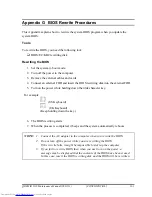
Page 412: ...Appendix G BIOS Rewrite Procedures G 2 CONFIDENTIAL QOSMIO G20 Maintenance Manual 960 511 ...

Page 413: ...e power while you are rewriting the EC KBC If the rewrite fails it might be impossible to start up the computer 4 If you fail to rewrite EC KBC then when you next turn on the power a message may be displayed that the contents of the EC KBC have been erased In this case insert the EC KBC rewriting disk and the EC KBC will be rewritten 5 Normally it takes about 30 seconds to rewrite the EC KBC It ma...

Page 414: ...ect an external FDD and insert the EC KBC rewriting disk into the external FDD 5 Turn on the power while holding down the Tab key Keep holding down the key until a message appears on the screen The EC KBC rewriting starts 6 When the EC KBC rewrite is completed the system is automatically turned off ...

Page 415: ...bility Appendix I Reliability The following table shows MTBF Mean Time Between Failures in maximum configuration Table I 1 MTBF Component Time hours System 6704 32 QOSMIO G20 Maintenance Manual 960 511 CONFIDENTIAL I 1 ...

Page 416: ...Appendix I Reliability I 2 CONFIDENTIAL QOSMIO G20 Maintenance Manual 960 511 ...

Page 417: ...tment No Perform the HDD Trouble shooting Procedure in Section 2 6 Yes Identify the failed HDD 2 Is the RAID configured by two HDD Reception Figure J 1 Flowchart of repairing TOSHIBA RAID 1 Refer to Check of RAID configuration in Section 3 2 in Chapter 3 2 Refer to Identifying failed HDD in Section 3 3 3 of Chapter 3 3 Refer to Analysis by Drive Log in section J 2 QOSMIO G20 Maintenance Manual 960...

Page 418: ...of failure 1 Which port of HDD failed Port 0 4 Change the status of the failed HDD to OFFLINE Replace the second HDD with new good one Replace the built in HDD with the second HDD removed 3 Does operation miss cause it Yes 2 If necessary analyze the Drive Log and identify the cause of failure Boot the independent utility and check the Physical Drive status Figure J 2 Flowchart of Analysis and hand...

Page 419: ...tility boot the independent utility to display the Drive Log To identify the failure cause of Port 0 analyze the Drive Log of REDUNDANT side of Port 1 To identify the failure cause of Port 1 analyze the Drive Log of REDUNDANT side of Port 0 Analyze this log 1 Find the log of message of Fail this drive last generated using PgUp and PgDn keys QOSMIO G20 Maintenance Manual 960 511 CONFIDENTIAL J 3 ...

Page 420: ... Analyze the detailed date of the message of right before of xxx Error IN xxx Error OUT for example DMA Error IN DMA Error OUT right before the log of Fail this drive message and identify the cause DMA Error IN DMA Error OUT J 4 CONFIDENTIAL QOSMIO G20 Maintenance Manual 960 511 ...

Page 421: ...A WRITE SECTORS W OUT ERASE O N 38h PO WRITE MULTIPLE EXT O N 39h PO WRITE LOG EXT O O 3Fh ND READ VERIFY SECOTR S M N 40h ND READ VERIFY SECOTR S EXT O N 42h ND SEEK M N 70h PI CFA TRANSLATE SECTOR O N 87h DD EXECUTE DEVICE DIAGNOSTIC M M 90h PO DOWNLOAD MICROCODE O N 92h P PACKET N M A0h PI IDENTIFY PACKET DEVICE N M A1h P SERVICE O O A2h ND SMART DISABLE OPERATIONS O N B0h ND SMART ENABLE DISAB...

Page 422: ...EXT O N Eah PI IDENTIFY DEVICE M N EC0 ND MEDIA EJECT O N EDh ND SET FEATURES M M Efh PO SECURITY SET PASSWORD O O F1h PO SECURITY UNLOCK O O F2h ND SECURITY ERASE PREPARE O O F3h PO SECURITY ERASE UNIT O O F4h ND SECURITY FREEZE LOCK O O F5h PO SECURITY DISABLE PASSWORD O O F6h ND READ NATIVE MAX ADDRESS O O F8h ND SET MAX ADDRESS O O F9h LBA Logical Block Address First sector address caused an e...

Page 423: ...1 In REDUNDANT of Port 0 find a log of Fail this drive message by PgUp and PgDn key 2 If no message of Fail this drive message it is judged that the second HDD is removed without the operation of removal by TOSHIBA RAID console and installed again 3 How to change the status to OFF LINE Release the status of Fail using the menu of Force OFFLINE This HDD is not necessary to be repaired QOSMIO G20 Ma...

Page 424: ...Redundant Log Each port has Own Log and Redundant Log As shown in the following figure the Port 0 has Own Log of Port0 and Redundant Log of Port1 The Port1 has Own Log of Port1 and Redundant Log of Port0 Redundant Log Data area Own Log Port1 Port0 RAID 0 or RAID 1 Redundant Own Log Data area Redundant Log Reserved area About 2MB Figure J 3 Drive Log 2 Information of Drive Log TOSHIBA RAID writes t...

Page 425: ...the FD storing the program of the Independent Utility in the FDD and boot the PC from the FD The following display appears In the Independent Utility the cursor is moved by with key and key Press Enter key to execute the option selected Press Esc key to return to the previous menu Pressing F1 key displays Help Press Esc key to exit QOSMIO G20 Maintenance Manual 960 511 CONFIDENTIAL J 9 ...

Page 426: ...Enable or Disable is displayed The default is Enable This option is displayed in RAID 1 Mirroring Degrade Bootup Displays if boot OS or not when the array is degraded Yes Boot up or No Not boot up is displayed The default is Yes This option is displayed in RAID 1 Mirroring MBR Protection Displays the setting of protection function of MBR Master Boot Record Enable Protect or Disable Not protect can...

Page 427: ...ings are displayed ONLINE The drive is working normally OFFLINE The drive is not configured as array and is not used FAIL The drive is failed and dose not work REBUILDING The drive is been rebuilding by data of normal drive or the rebuilding is suspended UNKNOWN There is controversy in the RAID information of other drive and the status is not decided It is displayed when this drive was removed and...

Page 428: ...its from the utility CAUTION Do not use the following item of the Independent Utility for maintenance Create Array This changes the current RAID configuration or information and delete user s data Do not use for maintenance Start Rebuild Resume Rebuild This changes the current RAID configuration or information and delete user s data Do not use for maintenance Modify Array This changes the current ...

Page 429: ...J Maintenance of TOSHIBA RAID J 3Operation of Independent utility The tree of Independent Menu is as follows Figure J 4 Tree of menu of Independent Utility QOSMIO G20 Maintenance Manual 960 511 CONFIDENTIAL J 13 ...

Page 430: ...e Size Designates the size of segment written in each disk of RAID 0 Striping The Stripe Size is only 64KB This parameter can be set only in the RAID 0 configured by two drives Write Cache Displays the setting of Write Cache of drive This can select Enable use or Disable not use The default is Enable use Degrade Bootup Displays if boot up OS or not When the array is degraded Yes boot up or No not ...

Page 431: ...RAID 1tion of with OFFLINE drive that has same or more size of capacity as the array in the condition of Optimal or Degraded During halt of rebuilding Resume Rebuild is displayed instead of Start Rebuild The procedure to rebuild drives is as follows 1 Put the cursor to the Start Rebuild in the main menu of Indent Utility and press Enter key 2 Select the direction to rebuild in Rebuild Direction me...

Page 432: ...atus of Physical Drive becomes Rebuilding and the progress rate expected remaining time and the number of errors are displayed During rebuilding the Rebuilding dialog to select Suspend or Abort is displayed It may take time depending on the drive capacity 6 To suspend the rebuilding put the cursor on Suspend when aborting on the Abort and press Enter key When Confirmation is displayed put the curs...

Page 433: ...builds maximum capacity of array The Rebuild Range menu is not displayed when the rebuild limit is not set or the rebuild limit is the same as the maximum capacity of array Normally designation of Effective is adequate 3 Put the cursor on OK in Confirmation and press Enter key The rebuild starts 4 During rebuilding Status of Physical Drive becomes REBILDING and the progress rate expected remaining...

Page 434: ...Range is set to Whole only Finish is can be selected after exceeding the Rebuild Limit When Finish is selected and OK is selected in Confirmation the rebuilding is completed at the time When OS is booted after exceeding the Rebuild Limit the rebuild is completed When completing the rebuild press OK to return to the main menu of Independent Setup Utility J 18 CONFIDENTIAL QOSMIO G20 Maintenance Man...

Page 435: ... set or the rebuild limit is the same as the maximum capacity of array Normally designation of Effective is adequate 3 To start the Check Media put the cursor to the Confirmation and press Enter key When an error is detected it automatically correct 4 During Check Media the progress rate expected remaining time and the number of errors are displayed in Progress of Physical Drive Check Media may ta...

Page 436: ...displayed The default is Enable use Degrade Bootup Displays if boot OS or not when the array is degraded Yes Boot up or No Not boot up is displayed The default is Yes This option is displayed in RAID 1 Mirroring MBR Protection Displays the setting of protection function of MBR Master Boot Record Enable Protect or Disable Not protect can be selected The default is Disable S M A R T Displays the set...

Page 437: ...D 1 working by one drive to RAID 1 working by two drives follow the procedure below 1 Select Modify Array in Main Menu 2 In Modify Array select array LDx that you want to change 3 In Modify Array select RAID 0 RAID 1 4 Select a drive in the condition of OFFLINE in Physical Drive which is expanded as RAID 1 with Space key After selecting drive Status changes to REBUILDING The capacity of drive that...

Page 438: ...OSHIBA RAID Delete Array Selects Delete Array of Setup Utility and delete array Put the cursor on the array you want to delete and press Enter key When Confirmation is displayed select OK to store the setting J 22 CONFIDENTIAL QOSMIO G20 Maintenance Manual 960 511 ...

Page 439: ...ed UNKNOWN There is controversy in the RAID information of other drive and the status is not decided It is displayed when this drive was removed and used in the past When this drive has been found good one setting to OFFLINE is possible by executing Force Offline S M A R T Displays the setting of failure prediction function of drive Enable or Disable is displayed The default is Enable When the lev...

Page 440: ...lows Table J 8 Function of option and key Option Explanation Change Port Changes log s port displayed and port s own log or redundant log Go to Event Inputting the log number in this number moves to the log of the number Key Function PageUp Scrolls upward one by one PageDown Scrolls downward one by one Home Jumps to oldest log in the latest 7 168 logs End Jumps to the latest log Ctrl Home Jumps to...

Page 441: ...nge log displayed put the cursor on Change Port and press Enter key 6 Select Drive log port to be displayed and Own Redundant For Example Own log means the drive log of Port 0 own Redundant log of Port 0 means the backup copy of the drive log of Port 1 7 To switch the upper and lower of drive log frame press Tab key The selected frame is displayed more lightly than the other frame 8 To move to the...

Page 442: ...The number displays the port that the drive is connected when the log is recorded The alphabet displays the degree of importance j means information W means warning and e means a error 6 Message Displays the content of log When the log is too much and it can not displayed in the area the remaining is displayed in Detail area 7 Range of log Displays the range of log number stored In this case it me...

Page 443: ... the oldest log in the latest 7 168 logs End Jumps to the latest log Ctrl Home Jumps to the oldest log that is older than 7 168 logs and the identification ID is recorded Tab Switches OWN window and REDUNDANT window Force OFFLINE Selecting this option in Physical Drive menu of Setup Utility can set the physical drive to offline by force Follow the procedure below 1 Select Physical Drive in Main Me...

Page 444: ...f Independent utility Appendix J Maintenance of TOSHIBA RAID J 28 CONFIDENTIAL QOSMIO G20 Maintenance Manual 960 511 Exit When this option is selected the utility is finished When Confirmation is displayed select OK ...

Reviews: