background image


 [CONFIDENTIAL] 


Toshiba Personal Computer 

PORTÉGÉ R500 

Maintenance Manual 


TOSHIBA CORPORATION


File Number 960-634 

First Edition

Summary of Contents for R500 S5001X - Portege - Core 2 Duo 1.2 GHz

Page 1: ... CONFIDENTIAL Toshiba Personal Computer PORTÉGÉ R500 Maintenance Manual TOSHIBA CORPORATION File Number 960 634 First Edition ...

Page 2: ...s manual s production However succeeding computers and manuals are subject to change without notice Therefore Toshiba assumes no liability for damages incurred directly or indirectly from errors omissions or discrepancies between any succeeding product and this manual Trademarks IBM is a registered trademark and IBM PC is a trademark of International Business Machines Corporation Intel Intel Speed...

Page 3: ...e of a hazard that could result in bodily injury if the safety instruction is not observed CAUTION Caution indicates the existence of a hazard that could result in property damage if the safety instruction is not observed NOTE Note contains general information that relates to your safe maintenance service Improper repair of the computer may result in safety hazards Toshiba requires service technic...

Page 4: ...nose and resolve FRU problems Chapter 3 Test and Diagnostics describes how to perform test and diagnostic operations for maintenance service Chapter 4 Replacement Procedures describes the removal and replacement of the FRUs Appendices The appendices describe the following Handling the LCD module Board layout Pin assignments Keyboard scan character codes Key layout Wiring diagrams BIOS rewrite proc...

Page 5: ...pears on the keyboard is printed in boldface type Key operation Some operations require you to simultaneously use two or more keys We identify such operations by the key top symbols separated by a plus sign For example Ctrl Pause Break means you must hold down Ctrl and at the same time press Pause Break If three keys are used hold down the first two and at the same time press the third User input ...

Page 6: ...pply 1 19 1 10 Batteries 1 22 1 11 AC Adaptor 1 25 Chapter 2 Troubleshooting Procedures 2 1 Troubleshooting 2 1 2 2 Troubleshooting Flowchart 2 2 2 3 Power Supply Troubleshooting 2 6 2 4 System Board Troubleshooting 2 15 2 5 USB FDD Troubleshooting 2 31 2 6 HDD Troubleshooting 2 35 2 7 Keyboard and Dual point Troubleshooting 2 40 2 8 Display Troubleshooting 2 42 2 9 Optical Drive Troubleshooting 2...

Page 7: ...6 3 14 Real Timer Test 3 29 3 15 NDP Test 3 31 3 16 Expansion Test 3 32 3 17 CD ROM DVD ROM Test 3 34 3 18 Error Code and Error Status Names 3 35 3 19 Hard Disk Test Detail Status 3 38 3 20 ONLY ONE TEST 3 40 3 21 Head Cleaning 3 49 3 22 Log Utilities 3 50 3 23 Running Test 3 52 3 24 Floppy Disk Drive Utilities 3 53 3 25 System Configuration 3 58 3 26 Wireless LAN Test Program Athetos 3 60 3 27 Wi...

Page 8: ...Base latch 4 26 4 10 Front panel Microphone 4 27 4 11 Bluetooth module 4 33 4 12 Touch pad 4 35 4 13 UWB module 4 40 4 14 Wireless LAN card 4 42 4 15 3G card 4 44 4 16 LAN jack 4 46 4 17 MJ board 4 47 4 18 RTC battery 4 50 4 19 RGB board 4 51 4 20 Sensor board 4 53 4 21 Fan Heat sink 4 54 4 22 PC card slot 4 57 4 23 System board and LCD cover assembly 4 58 4 24 LCD mask 4 61 4 25 LCD unit 4 63 4 2...

Page 9: ... the LCD Module A 1 Appendix B Board Layout B 1 Appendix C Pin Assignments C 1 Appendix D Keyboard Scan Character Codes D 1 Appendix E Key Layout E 1 Appendix F Wiring Diagrams F 1 Appendix G BIOS rewrite Procedures G 1 Appendix H EC KBC rewrite Procedures H 1 Appendix I Reliability I 1 ...

Page 10: ...x CONFIDENTIAL PORTÉGÉ R400 Maintenance Manual 960 623 ...

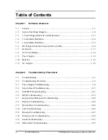
Page 11: ... CONFIDENTIAL Chapter 1 Hardware Overview ...

Page 12: ...1 Hardware Overview 1 ii CONFIDENTIAL PORTEGE R500 Maintenance Manual 960 634 ...

Page 13: ...oppy Disk Drive USB External 1 13 1 4 2 5 inch Hard Disk Drive 1 14 1 5 1 8 inch Hard Disk Drive 1 15 1 6 DVD Super Multi Drive Optical Drive ODD 1 16 1 7 Keyboard 1 17 1 8 TFT Color Display 1 18 1 8 1 LCD Module 1 18 1 9 Power Supply 1 19 1 10 Batteries 1 22 1 10 1 Main Battery 1 22 1 10 2 Battery Charging Control 1 23 1 10 3 RTC battery 1 24 1 11 AC Adaptor 1 25 ...

Page 14: ...5 Figure 1 8 Keyboard 1 17 Figure 1 8 LCD module 1 18 Tables Table 1 1 3 5 inch FDD specifications 1 13 Table 1 2 2 5 inch HDD specifications 1 14 Table 1 3 1 8 inch HDD specifications 1 15 Table 1 4 DVD Super Multi drive specifications 1 16 Table 1 5 LCD module specifications 1 18 Table 1 6 Power supply output rating 1 20 Table 1 7 Battery specifications 1 22 Table 1 8 Time required for charges 1...

Page 15: ...r CMOS technology extensively to provide compact size minimum weight low power usage and high reliability This computer incorporates the following features There are some models and options according to BTO system Refer to the Parts List for the configuration of each model and options Microprocessor The PORTÉGÉ R500 computer is equipped with one of the following processors Intel CoreTM 2 Duo ULV 1...

Page 16: ... type low temperature poly silicon TFT color display External monitor Supported via an RGB connector Keyboard An easy to use 85 US 87 UK key keyboard provides a numeric keypad overlay for fast numeric data entry or for cursor and page control The keyboard also includes two keys that have special functions in Microsoft Windows Vista It supports software that uses a 101 or 102 key enhanced keyboard ...

Page 17: ...xternal monitor RGB port The port enables connection of an external monitor which is recognized automatically by Video Electronics Standards Association VESA Display Data Channel DDC 2B compatible functions PC card slot A PC card slot are provided The PC card slot PCMCIA accommodates one Type II card or Express Slot Choose only one SD SDHC memory card slot One SD SDHC memory card slot Data can be ...

Page 18: ...n of an optional Slim Port Replicator II It provides additional features as follows RJ45 LAN jack External monitor port DC IN 15V jack Security lock slot Universal Serial Bus 2 0 port four DVI port Sound system The sound system is equipped with the following features speakers Volume control Stereo headphone jack External microphone jack Built in microphone ...

Page 19: ...s per second 1000BASE T It also supports Wakeup on LAN WOL Magic Packet and LED θ Wireless LAN The computer is equipped with PCI Ex MiniCard type wireless LAN board that supports 802 11 b g 802 11 a b g or 802 11 a b g n in the PCI Ex MiniCard slot This function can be switched on and off by a switch on the computer Bluetooth The computer is equipped with Bluetooth V2 0 EDR communications standard...

Page 20: ...1 Hardware Overview 1 1 Features The front of the computer is shown in figure 1 1 Figure 1 1 Front of the computer 1 6 CONFIDENTIAL PORTEGE R500 Maintenance Manual 960 634 ...

Page 21: ...1 1 Features 1 Hardware Overview The system unit configuration is shown in figure 1 2 Figure 1 2 System unit configuration PORTEGE R500 Maintenance Manual 960 634 CONFIDENTIAL 1 7 ...

Page 22: ... Overview 1 2 System Unit Block Diagram 1 2 System Unit Block Diagram Figure 1 3 is a block diagram of the system unit Figure 1 3 System unit block diagram 1 8 CONFIDENTIAL PORTEGE R500 Maintenance Manual 960 634 ...

Page 23: ... 478 pin Micro FC PGA package Processor Number Memory One memory slots capable of accepting DDR2 SDRAM 512MB or 1024MB memory modules for a maximum of 2GB on board 1GB 200 pin Small Outline DIMM 1 8V operation PC2 4200 DDR2 533 PC2 5300 DDR2 667 support North Bridge Intel Calistoga GMS Intel 945GMS Processor Support Core 2 Duo ULV case of PORTEGE R500 Supports System Memory DDR2 400 DDR2 533 DDR2 ...

Page 24: ...r Azalia USB 1 1 2 0 Controller 8 ports Built in LAN controller WfM 2 0 IEEE 802 3 compliance Power Management ACPI 2 0 compliance SMBus2 0 controller SPI interface BIOS Low Pin Count LPC interface EC KBC Super I O IRQ controller Serial Interrupt Function Suspend Resume control Built in RTC GPIO 652 ball 31 31 2 51mm BGA Package Cardbus controller TI PCI8412ZHK PCI Interface PCI Rev 2 2 SD IO Cont...

Page 25: ...phone jack External microphone jack Built in microphone Modem Controller One MDC is used This controller has the following functions One RJ11 port Azalia MDC1 5 V 92 V 90 56K Modem FAX Ring wake up support Internal LAN Controller Ethernet LAN 10 megabits per second 10BASE T Fast Ethernet LAN 100 megabits per second 100BASE TX or Gigabit Ethernet LAN 1000 megabits per second 1000BASE T is used Supp...

Page 26: ... R500 Maintenance Manual 960 634 Wireless LAN One PCI Ex MiniCard Intel Golan b g Golan a b g Intel Kedlon a b g n Atheros b g Atheros a b g Supports Wireless Communication SW Bluetooth V2 0 EDR Sensor Thermal Sensor One ADM1032ARMZ chip is used LCD Sensor Acceleration Sensor ...

Page 27: ...e FDD is shown in figure 1 4 The specifications for the FDD are listed in Table 1 1 Figure 1 4 3 5 inch FDD USB External Table 1 1 3 5 inch FDD specifications TEAC FD 05PUB 337 G8AC0000B320 Items 720KB mode 1 44MB mode FDD part 250K bits second 500K bits second Data transfer rate USB Full speed mode 12M bits second Disk rotation speed 300rpm Track density 5 3 track mm 135TPI PORTEGE R500 Maintenan...

Page 28: ...ble 1 2 Figure 1 5 2 5 inch HDD Table 1 2 2 5 inch HDD specifications Items Specifications TOSHIBA HDD2D63BZL01 TOSHIBA HDD2D61BZL01 TOSHIBA HDD2D62BZL01 TOSHIBA HDD2D60BZL01 Outline Width mm 100 0 Dimensions Height mm 9 5 Depth mm 69 85 Weigh t g 98 max 102 max Storage size formatted 60GB 80GB 120GB 160GB Speed RPM 5 400 Data transfer speed Internal Transfer rate Host Transfer rate 335 613 Mbits ...

Page 29: ...6 1 8 inch HDD Table 1 3 1 8 inch HDD specifications 1 8 inch HDD Specifications Items Specifications TOSHIBA HDD1682BZM01 TOSHIBA HDD1789BZM01 Outline Width mm 54 0 0 2 Dimensions Height mm 5 0 0 35 8 0 0 35 Depth mm 71 0 0 3 Weight g 48 max 59 max Storage size formatted 40GB 100GB Speed RPM 4 200 Internal Transfer rate Mbits s 165 0 356 8 176 90 382 9 Host interface transfer rate Mbytes s 100 Ul...

Page 30: ...Mass g 87 5 bezel included Data transfer speed Read DVD ROM CD ROM Max 8x CAV Max 24x CAV Data transfer speed Write CD R CD RW DVD R DVD RW DVD R DVD RW DVD RAM Max 16x ZCLV Max 10x CLV Ultra speed Max 8x ZCLV Max 4x ZCLV Max 8x ZCLV Max 4x ZCLV Max 3x ZCLV 4 7GB ATAPI Burst MB s PIO Mode DMA Mode Ultra DMA Mode 16 6 PIO MODE4 16 6 Multi Word Mode2 33 3 Ultra DMA Mode2 Data Buffer Capacity 2MB Acc...

Page 31: ...ey and control key and in conformity with JIS The keyboard is connected to membrane connector on the system board and controlled by the keyboard controller Figure 1 7 is a view of the keyboard See Appendix E about a layout of the keyboard Figure 1 7 Keyboard PORTEGE R500 Maintenance Manual 960 634 CONFIDENTIAL 1 17 ...

Page 32: ...th 1 200 x 800 resolution The VGA in North Bridge can control internal and external WXGA support displays simultaneously Figure 1 8 shows a view of the LCD module and Table 1 5 lists the specifications Figure 1 8 LCD module Table 1 5 LCD module specifications Specifications Item 12 1 inch WXGA TFT TMD G33C00047110 210 Number of Dots 1 280 W x 800 H Dot spacing mm 0 204 H x 0 204 V Display range mm...

Page 33: ...ter is connected to the computer 2 Detects DC output and circuit malfunctions 3 Controls the battery icon and DC IN icon 4 Turns the battery charging system on and off and detects a fully charged battery 5 Turns the power supply on and off 6 Provides more accurate detection of a low battery 7 Calculates the remaining battery capacity 8 Controls the transmission of the status signal of the main bat...

Page 34: ...NO NO NO CRT D E3V 3 3 Yes Yes NO NO Dock D E5V 5 Yes Yes NO NO Dock E3V 3 3 Yes Yes NO NO ICH7 M PCI e Mini Card WLAN 3G Finger Sensor E5V 5 Yes Yes NO NO ICH7 M USB Power FS E3V 3 3 Yes NO Yes NO NO Finger Sensor LAN1R2 E1V 1 2 Yes Yes NO NO LAN LAN2R5 E2V 2 5 Yes Yes NO NO LAN LAN E3V 3 3 Yes Yes NO NO LAN LEDBL PYV 15 20 NO NO NO LCD LED Backlight M5V 5 Yes Yes NO LED MCV 5 Yes Yes NO PSC MCVC...

Page 35: ...5 NO NO NO ICH7 M ODD HDD SATA PC Card Power LED KB PAD CRT FAN LED Backlight AN12945A PNL P2V 2 5 NO NO NO LCD PPV 1 500 0 300 NO NO NO CPU PTV 1 05 NO NO NO Clock Generator CPU GMCH ICH7 M R3V 2 0 3 5 Yes Yes Yes ICH7 M RTC S3V 3 3 Yes Yes NO EC KBC SD P3V 3 3 NO NO NO SD Slot UIMPWR E3V 3 3 Yes Yes NO NO SIM Slot 3G VDDA E3V 3 3 Yes NO Yes NO NO Finger Sensor WFLN E3V 3 3 Yes Yes NO NO WLAN WIM...

Page 36: ... Table 1 7 Battery specifications Battery name Material Output voltage Capacity G71C00085110 210 Lithium Ion 10 8 V 2 900 mAh Main battery G71C00086110 210 Lithium Ion 10 8 V 5 800 mAh RTC battery GDM710000041 NiMH 2 4 V 15mAh 1 10 1 Main Battery The removable main battery pack is the computer s main power source when the AC adaptor is not attached The main battery maintains the state of the compu...

Page 37: ...ry type Power on hours Power off hours Battery 2 900 mAh About 5 0 to 7 5 About 5 0 Battery 5 800 mAh About 6 5 to 15 0 About 5 0 NOTE The time required when the system is powered on is affected by the amount of power the system is consuming Use of the fluorescent lamp and frequent disk access diverts power and lengthens the charge time If any of the following occurs the battery charge process sto...

Page 38: ...des power to keep the current date time and other setup information in memory while the computer is turned off Table 1 9 lists the charging time and data preservation period of the RTC battery Table 1 9 RTC battery charging data preservation time Status Time Charging Time power on 24 hours Data preservation period full charge 30 days ...

Page 39: ...rge the battery Table 1 10 lists the AC adapter specifications Table 1 10 AC adapter specifications Parameter Specification G71C0004A510 3 pin G71C00062210 2 pin Power 60W Peak 75W Input voltage 100V 240V Input frequency 50Hz to 60Hz Input current 1 5A or less 100V 240V 4Aload Output voltage 15V Output current 0A to 4A At constant voltage mode ...

Page 40: ...1 Hardware Overview 1 11 AC Adapter 1 26 CONFIDENTIAL PORTEGE R500 Maintenance Manual 960 634 ...

Page 41: ... CONFIDENTIAL Chapter 2 Troubleshooting Procedures ...

Page 42: ...2 Troubleshooting Procedures 2 ii CONFIDENTIAL PORTEGE R500 Maintenance Manual 960 634 ...

Page 43: ...rocedure 3 Diagnostic Test Program Execution Check 2 29 Procedure 4 Replacement Check 2 30 2 5 USB FDD Troubleshooting 2 31 Procedure 1 USB FDD Head Cleaning Check 2 31 Procedure 2 Diagnostic Test Program Execution Check 2 32 Procedure 3 Connector Check 2 33 Procedure 4 Replacement Check 2 34 2 6 HDD Troubleshooting 2 35 Procedure 1 Message Check 2 35 Procedure 2 Partition Check 2 36 Procedure 3 F...

Page 44: ...cution Check 2 46 Procedure 2 Connector Check and Replacement Check 2 46 2 11 Bluetooth Troubleshooting 2 47 Procedure 1 Diagnostic Test Program Execution Check 2 47 Procedure 2 Connection Check 2 48 Procedure 3 Replacement Check 2 49 2 12 Wireless LAN Troubleshooting 2 50 Procedure 1 Transmitting Receiving Check 2 50 Procedure 2 Antenna Connection Check 2 51 Procedure 3 Replacement Check 2 52 2 1...

Page 45: ...60 634 CONFIDENTIAL 2 v 2 15 Fingerprint sensor Troubleshooting 2 56 Procedure 1 Setting Windows Log ON password 2 57 Procedure 2 Registration of fingerprint 2 57 Procedure 3 Authentication of fingerprint 2 58 Procedure 4 Connector Check and Replacement Check 2 59 ...

Page 46: ...shooting flowchart 2 3 Figure 2 2 Debug port Boot mode error status 2 19 Tables Table 2 1 Battery icon 2 6 Table 2 2 DC IN icon 2 6 Table 2 3 Error code 2 7 Table 2 4 Result code 2 13 Table 2 5 Debug port Boot mode error status 2 21 Table 2 6 FDD error code and status 2 32 Table 2 7 HDD error code and status 2 38 ...

Page 47: ... Detailed Replacement Procedures are given in Chapter 4 Replacement Procedures The following tools are necessary for implementing the troubleshooting procedures The following tools are necessary for implementing the Diagnostics procedures For tools required for executing the Test Program refer to the Chapter3 For tools required for disassembling assembling refer to the Chapter 4 1 A set of tools f...

Page 48: ...ch FRU malfunctions Before going through the flowchart steps check the following Ask the user if a password is registered and if it is ask him or her to enter the password Make sure that Toshiba Windows is installed on the hard disk Non Toshiba operating systems can cause the computer malfunction Make sure all optional equipment is removed from the computer Make sure the USB FDD and optical drive ...

Page 49: ...2 2 Troubleshooting Flowchart 2 Troubleshooting Procedures Figure 2 1 Troubleshooting flowchart 1 2 PORTEGE R500 Maintenance Manual 960 634 CONFIDENTIAL 2 3 ...

Page 50: ...2 Troubleshooting Procedures 2 2 Troubleshooting Flowchart Figure 2 1 Troubleshooting flowchart 2 2 2 4 CONFIDENTIAL PORTEGE R500 Maintenance Manual 960 634 ...

Page 51: ...nd Dual point Troubleshooting Procedures in Section 2 7 5 If an error is detected on the display test perform the Display Troubleshooting Procedures in Section 2 8 6 If an error is detected on the CD ROM DVD ROM test perform the Optical Drive Troubleshooting Procedures in Section 2 9 7 If an error is detected on the modem test perform the Modem Troubleshooting Procedures in Section 2 10 8 If an er...

Page 52: ... supply status Battery icon DC IN icon The power supply controller displays the power supply status through the Battery icon and the DC IN icon in the LCD as listed in the tables below To check the power supply status install a battery pack and connect an AC adaptor Table 2 1 Battery icon Battery icon Power supply status Lights orange Battery has been charging and AC adapter is connected Lights gr...

Page 53: ... malfunction it indicates the error code as shown below The error code begins with the least significant digit Table 2 3 Error code Error code Where Error occurs 1 h AC Adaptor 2 h 1st Battery 3 h 2nd Battery 4 h S3V output 5 h E5V output 6 h E3V output 7 h 1R5 E1V output 8 h 1R8 B1V output 9 h PPV output A h PTV output B h 1R5 E1V output C h 1R8 B1V output D h PPV output E h PTV output F h ...

Page 54: ...t battery discharge current over 0 5A when there is no load 23h 1st battery charge current is over 3 5A in charging 24h The compensation value of 0A is not within the limits from design data 400mA 25h 1st battery charge current is over 0 3A in not charging 2nd Battery Error code Meaning 32h 2nd battery discharge current is over 0 5A when there is no load 33h 2nd battery charge current is over 2 7A...

Page 55: ...e is under 2 81V when the computer is powered on 62h E3V voltage is under 2 81V when the computer is booting up 64h E3V voltage is under 2 81 V when EV power is maintained 1R5 E1V output Error code Meaning 70h 1R5 E1V voltage is over 1 80V when the computer is powered on off 71h 1R5 E1V voltage is under 1 275V when the computer is powered on 72h 1R5 E1V voltage is under 1 275V when the computer is...

Page 56: ...over 1 80V when the computer is powered on off B1h 1R5 E1V voltage is under 1 275V when the computer is powered on B2h 1R5 E1V voltage is under 1 275V when the computer is booting up B4h 1R5 E1V voltage is under 1 275V when EV power is maintained and OUTV7 EV is designated 1R8 B1V output Error code Meaning C0h 1R8 B1V voltage is over 2 16V when the computer is powered on off C1h 1R8 B1V voltage is...

Page 57: ...k 2 In the case of error code 10h or 12h Make sure the AC adaptor cord and AC power cord are firmly plugged into the DC IN 15 V socket and wall outlet If the cables are connected correctly go to the following step Connect a new AC adaptor and or AC power cord if necessary If the error still exists go to Procedure 5 Check 3 In the case of error code 2Xh Make sure the battery pack is correctly insta...

Page 58: ...to Check 3 Check 3 Make sure the DC IN jack is firmly connected to the connector CN8800 on the system board If the DC IN jack is not firmly connected go to Procedure 5 If it is connected go to Check 4 Check 4 Use a multimeter to make sure the AC adaptor output voltage is close to 15 V If the output is several percent lower than 15 V go to Check 5 If the output is close to 15 V go to Check 6 Check ...

Page 59: ...adaptor s output voltage is not normal Check 1 4 The battery is not installed Check 2 5 The battery s output voltage is not normal Check 3 6 The battery s temperature is not normal Check 4 7 A bad battery is installed Check 2 8 Any other problems Check 5 Check 1 Make sure the AC adaptor and AC power cord are firmly plugged into the DC IN socket and the wall outlet If these cables are connected cor...

Page 60: ...puter following the steps described in Chapter 4 Replacement Procedures Check the connection between the AC adaptor and system board and connection After checking the connections perform the following Check 1 Check 1 Replace the AC adaptor with a new one If the AC adaptor is still not functioning properly perform Check 2 Check 2 Replace the system board with a new one following the steps described...

Page 61: ...cribes how to determine if the system board and CPU are defective or not functioning properly Start with Procedure 1 and continue with the other procedures as instructed The procedures described in this section are Procedure 1 Message Check Procedure 2 Printer Port LED Check on Boot Mode Procedure 3 Diagnostic Test Program Execution Check Procedure 4 Replacement Check ...

Page 62: ...structs These errors occur when the system configuration preserved in the RTC memory CMOS type memory is not the same as the actual configuration or when the data is lost If you press F1 as the message instructs returns all system settings to their default values Then the system reboots If error message b appears often when the power is turned on replace the RTC battery If any other error message ...

Page 63: ...appears go to the HDD Troubleshooting Procedures in Section 2 6 If the error message 21 appears go to the Optical Drive Troubleshooting Procedures in Section 2 9 1 PIT ERROR 2 MEMORY REFRESH ERROR 3 TIMER CH 2 OUT ERROR 4 CMOS CHECKSUM ERROR 5 CMOS BAD BATTERY ERROR 6 FIRST 64KB MEMORY ERROR 7 FIRST 64KB MEMORY PARITY ERROR 8 VRAM ERROR 9 SYSTEM MEMORY ERROR 10 SYSTEM MEMORY PARITY ERROR 11 EXTEND...

Page 64: ...le refer to Chapter 4 2 Connect the debug port test cable and RS 232C cross cable to the test board 3 Connect the RS 232C Cross cable to the PC that displays the test results 4 Boot the compute1r in DOS mode 5 Execute GETDPORT COM in the text menu in CPU REAL mode Insert the FD for starting D port into FDD and input FD starting drive dport The D port status is displayed in the following form 6 Whe...

Page 65: ...cksum skip when returned to S3 halts when error F000H CHECK SUM CHECK Checksum other than boot block skip when returned to S3 EC KBC rewrite check If rewrite is requested go to BIOS rewrite process Transition to system BIOS IRT when returned to S3 Key input F001H When a key is pressed check if it is Tilde key or Tab key F002H Initialization of SC F005H F006H BIOS rewrite request check If Checksum ...

Page 66: ... cycle 2s on 1s off 1s BIOS ROM error Blinks orange cycle 2s On 1s Off 1s Prohibition of USB BEEP Key input Waiting for key input FDC reset Setting parameters for 2HD 1 44MB Reading of first sector If it is the data of 1 44MB 2HD the media type is definite Setting of parameters for 2DD 720KB Retrieval of CHGBIOSA EXE from the root directory Directory start header and calculates the sector Read 1 s...

Page 67: ...g the refresh interval to 30μs Check of DRAM type and size at cold boot When unsupported memory is connected becoming HLT after beep sound HLT when DRAM size is 0 F101H SM RAM stack area test HLT When it can not be used as a stack Cache configuration Cache permission L1 L2 Cache CMOS access test at cold boot HLT when an error is detected Battery level check of CMOS CMOS checksum check Initializati...

Page 68: ...SM_EXTMEM_ERR PnP RAM checksum check Resume error F177H RSM_PNPRAM_ERR Transition to RESUME MAIN Reset of CPU clock to low Prohibition of all SMI Clearance of resume status Return to ROM Turning area of C0000h to EFFFFh to PCI Prohibition of DRAM Resume error process Setting of resume error request F103 Copying ROM RAM of system BIOS HLT when error occurs F104H BIOS signature check case of cold bo...

Page 69: ...2 Check whether the speaker gate works normally CPU clock measurement Check of parameter block A Permission of SMI except auto off function Control of excess of rated input power Battery discharging current control 1CmA AC adapter rated over current control Dividing procedures for time measuring by IRT Setting for clock generator F106H Initialization of devices which need initialization before PCI...

Page 70: ...initialization Control of built in LAN permission prohibition PIC initialization PIC test F107H Password Initialization PCI bus initialization connection of DS Bus Initialization of LAN information F108H Check of WakeUp factor Task generation for waiting INIT_PCI completion CMOS data initialization 2 PnP initialization Setting of setup items Waiting for the completion of Multi box status check F10...

Page 71: ...start Enabling power off F10BH Output code generation F10CH FIRST_64KB_CHECK Check of first 64KB memory F10DH INIT_INT_VECTOR Initialization of vectors F10EH INIT_NDP Initialization of NDP Storing of CMOS error status to IRT_ERR_STS_BUF Timer initialization start EC initialization Reading of battery information F10FH INIT_SYSTEM Initialization of system Update of system BIOS Update of EDID informa...

Page 72: ...t F119H CHECK_DMAC Initialization of DMAC Boot F11AH INIT_DMAC Initialization of DMA Boot F11CH CHECK_SIO Check of SIO For models supporting SIO Check of password In the case of Reboot Waiting for HDD initialization completion Check of key input during IRT waiting for KBC initialization completion Initialization of ATA priority In the case of Boot BM loading process for models supporting fingerpri...

Page 73: ... Link initialization completion Renewal of table for DMI Copying ACPI table to uppermost of extension memory waiting for writing completion of PSC Version BIOS Waiting for completion of setting clock generator When error occurred halt at F121 Waiting for completion of initialization of Serial port for models supporting SIO Cancel of NMI Mask TIT check sum Clear of the IRT flag of Runtime side Upda...

Page 74: ...alization completion for models supporting Bluetooth Update of DMI Wakeup factor Update of SM BIOS structure table PCI device configuration space close Cache control Renewal of the parameter block A Process for CPU Make the CPU clock to be set by SETUP Waiting of motor off completion of disabled HDD Final decision of USB FDD drive information Post processing of PRE_BOOT_SETUP Clear of PWRBTN_STS E...

Page 75: ...stic Test Menu Refer to Chapter 3 Tests and Diagnostics for more information on how to perform these tests 1 System test 2 Memory test 3 Keyboard test 4 Display test 5 Floppy Disk test 6 Async test 7 Hard Disk test 8 Real Timer test 9 NDP test 10 Expansion test 11 CD ROM DVD ROM test 12 Wireless LAN test 13 Sound test 14 LAN Modem Bluetooth IEEE1394 test If an error is detected during these tests ...

Page 76: ...r following the steps described in Chapter 4 Replacement Procedures and perform Check 1 Check 1 Visually check for the following a Cracked or broken connector housing b Damaged connector pins If their connectors are in good condition but there is still a problem go to Check 2 Check 2 The system board may be damaged Replace the system board with a new one following the steps described in Chapter 4 ...

Page 77: ...Cleaning Check Procedure 2 Diagnostic Test Program Execution Check Procedure 3 Connector Check Procedure 4 Replacement Check Procedure 1 USB FDD Head Cleaning Check USB FDD head cleaning operation details are given in Chapter 3 Tests and Diagnostics Insert the Diagnostics Disk in the computer s floppy disk drive turn on the computer and run the test Clean the USB FDD heads using the cleaning kit I...

Page 78: ...at the write protect tab is disabled If any other errors occur while executing the FDD diagnostics test go to Check 1 Table 2 6 FDD error code and status Code Status 01h Bad command error 02h Address mark not found 03h Write protected 04h Record not found 06h Media removed 08h DMA overrun error 09h DMA boundary error 10h CRC error 20h FDC error 40h Seek error 60h Not drive error 80h Time out error...

Page 79: ...he following figure Check 1 Check the connection of the USB FDD If the USB FDD is still not functioning properly perform Check 2 Check 2 As the connection may be defective disassemble the computer and check each connection If the problem still occurs go to Procedure 4 PORTEGE R500 Maintenance Manual 960 634 CONFIDENTIAL 2 33 ...

Page 80: ... the steps in Chapter 4 Replacement Procedures If the problem still occurs perform Check 2 Check 2 USB board FFC may be faulty Replace it with a new one following the steps in Chapter 4 Replacement Procedures If the problem still occurs perform Check 5 Check 3 Jack board may be faulty Replace it with a new one following the steps in Chapter 4 Replacement Procedures If the problem still occurs perf...

Page 81: ...e Check When the computer s HDD does not function properly some of the following error messages may appear on the display Start with Check 1 below and perform the other checks as instructed Check 1 If any of the following messages appear go to Procedure 5 If the following messages do not appear perform Check 2 HDC ERROR After 5 seconds this message will disappear or IDE 0 ERROR After 5 seconds thi...

Page 82: ...eck 3 If drive C is listed as active in the FDISK menu go to Check 4 If drive C is not listed as active return to the FDISK menu and choose the option to set the active partition for drive C Restart the computer and then go to Procedure 3 Check 4 Remove the FD and restart the computer If the problem still exists go to Procedure 3 Check 5 Using the SYS command on the Toshiba DOS system disk install...

Page 83: ...message appears on the display the HDD is formatted Format complete If an error message appears on the display refer to the Toshiba DOS Manual for more information and perform Check 2 Check 2 Using the Diagnostics Disk format the HDD with a low level format option Refer to Chapter 3 Tests and Diagnostics for more information about the diagnostic program If the following message appears on the disp...

Page 84: ...ith a new one following the instructions in Chapter 4 Replacement Procedures The error codes and statuses are listed in Table 2 7 If an error code is not generated or the problem still exists go to Procedure 5 Table 2 7 HDD error code and status Code Status 01h Bad command error 02h Address mark not found 04h Record not found 05h HDC not reset 07h Drive not initialized 08h Overrun error DRQ ON 09h...

Page 85: ...are loose reconnect firmly and repeat Procedure 1 If there is still an error go to Check 2 Check 2 The HDD may be damaged Replace it with a new one following the instructions in Chapter 4 Replacement Procedures If the problem still exists perform Check 3 Check 3 The HDD FPC may be damaged Replace it with a new one following the instructions in Chapter 4 Replacement Procedures If the problem still ...

Page 86: ...res Start with Procedure 1 and continue with the other procedures as instructed Procedure 1 Diagnostic Test Program Execution Check Procedure 2 Connector Check and Replacement Check Procedure 1 Diagnostic Test Program Execution Check Execute the Keyboard Test in the Diagnostic Program Refer to Chapter 3 Tests and Diagnostics for more information on how to perform the test program If an error occur...

Page 87: ...ere is still an error go to Check 2 Check 2 The keyboard or its cable may be damaged Replace it with a new one following the instructions in Chapter 4 Replacement Procedures If the problem still exists perform Check 5 Check 3 Make sure the touch pad cable is securely connected to CN9850 on the system board If the connection is loose reconnect firmly and go to Procedure 1 If there is still an error...

Page 88: ... The Display Test program is stored on the computer s Diagnostics disk This program checks the display controller on the system board Insert the Diagnostics disk in the computer s floppy disk drive turn on the computer and run the test Refer to Chapter 3 Tests and Diagnostics for details If an error is detected go to Procedure 2 Procedure 2 Connector Check and Cable Check Check 1 Make sure the LCD...

Page 89: ...he LCD cable with a new one following the instructions in Chapter 4 Replacement Procedures and test the display again If the problem still exists perform Check 2 Check 2 Replace the LCD module with a new one following the instructions in Chapter 4 Replacement Procedures and test the display again If the problem still exists perform Check 3 Check 3 The display controller on the system board may be ...

Page 90: ... procedures as required Procedure 1 Diagnostic Test Program Execution Check Procedure 2 Connector Check and Replacement Check Procedure 1 Diagnostic Test Program Execution Check The CD ROM DVD ROM test program is stored in the Diagnostics Disk For the test prepare test Media Then insert the Diagnostics Disk in the computer s floppy disk drive turn on the computer and run the test Refer to Chapter ...

Page 91: ... repeat Procedure 1 If there is still an error go to Check 2 Check 2 The Optical drive may be defective or damaged Replace the drive with a new one If there is still an error go to Check 3 Check 3 The ODD FPC may be defective or damaged Replace the drive with a new one If there is still an error go to Check 4 Check 4 The SD board may be defective or damaged Replace the drive with a new one If ther...

Page 92: ...edure 2 Connector Check and Replacement Check The RJ 45 jack with LAN cable is connected to the system board If the LAN malfunctions the system board might be damaged Disassemble the computer following the steps described in Chapter 4 Replacement Procedures and perform the following check Check 1 Make sure the RJ 45 jack is firmly connected to J4100 on the system board If the connector is disconne...

Page 93: ...Test Program Execution Check Make sure the wireless switch on the left side of the computer is turned On If it is not slide the switch toward the back of the computer to turn it on Check 1 Execute Bluetooth test program Perform the test following the instructions described in Chapter 3 Bluetooth Test Program You will need a second computer that can communicate by the Bluetooth If the computer pass...

Page 94: ...ecks Check 1 Make sure the Bluetooth module is firmly connected to CN4400 on the sound board If the connector is disconnected connect it firmly If the Bluetooth module is still not functioning properly perform Check 2 Check 2 Make sure the Bluetooth antenna cable is firmly connected to the Bluetooth module If the Bluetooth antenna cable is disconnected connect it firmly If the Bluetooth module is ...

Page 95: ...ng checks Check 1 The Bluetooth module may be defective or damaged Replace the Bluetooth module with a new one following the steps in Chapter 4 Replacement Procedures If the Bluetooth is still not functioning properly perform Check 2 Check 2 The Bluetooth antenna may be defective or damaged Replace the Bluetooth antenna with a new one following the steps in Chapter 4 Replacement Procedures If the ...

Page 96: ...edure 3 Replacement Check Procedure 1 Transmitting Receiving Check Make sure the wireless switch on the left side of the computer is turned On If it is not slide the switch toward the back of the computer to turn it on Refer to Chapter 3 Tests and Diagnostics for more information on how to perform the test program Check 1 Execute test program for the wireless LAN function to check the transmitting...

Page 97: ...ck 1 Make sure the wireless LAN board is firmly connected to CN2600 on the system board If the connector is disconnected connect it firmly If the wireless LAN board is still not functioning properly perform Check 2 Check 2 Make sure the wireless LAN antenna cables are firmly connected to the wireless LAN board If the wireless LAN antenna cables are disconnected connect them firmly If the wireless ...

Page 98: ...erform the following checks Check 1 The wireless LAN board may be defective or damaged Replace the board with a new one following the steps in Chapter 4 Replacement Procedures If the problem still exists perform Check 2 Check 2 The wireless LAN antenna may be defective or damaged Replace the antenna with a new one following the steps in Chapter 4 Replacement Procedures If the problem still exists ...

Page 99: ...iagnostic Test Program Execution Check Procedure 2 Connecor Check Procedure 3 Replacement Check Procedure 1 Diagnostic Test Program Execution Check Execute the Sound test in Sound Test program disk Refer to Chapter 3 Tests and Diagnostics for more information on how to perform the test program If any error is detected by the test go to Procedure 2 Procedure 2 Connector Check The connection of soun...

Page 100: ...problem still occurs perform Check 5 Check 2 External microphone may be faulty Replace it with a new one following the steps in Chapter 4 Replacement Procedures If the problem still occurs perform Check 5 Check 3 Speaker may be faulty Replace it with a new one following the steps in Chapter 4 Replacement Procedures If the problem still occurs perform Check 5 Check 4 Internal microphone may be faul...

Page 101: ...card can be read If the card is not recognized or data are not read go to Procedure 2 Procedure 2 Connector Check and Replacement Check Check 1 The connection of SD system is shown in the following figure If any of the connections is loose reconnect firmly and repeat Procedure 1 If there is still an error go to Check 2 Check 2 The SD board may be defective or damaged Replace the drive with a new o...

Page 102: ...s instructed When failed in Procedure 1 to Procedure 3 execute Procedure 4 Procedure 1 Setting Windows Log ON password Procedure 2 Registration of fingerprint Procedure 3 Authentication of fingerprint Procedure 4 Connector Check and Replacement Check CAUTION Scan your finger shown below 1 Lay your finger straight to the sensor and put lightly the first joint of your finger at the centerline of the...

Page 103: ...he previously enrolled fingerprints is selected again the latest information will be enrolled and any previous information over written 4 The Fingerprint Enrollment screen will be displayed and the tutorial will begin First click Replay video and confirm the proper movement for the finger you wish to register Then confirm the message displayed on this screen and ensure that there is a check mark i...

Page 104: ...indows 2 In the Windows logon window put lightly the first joint of your finger registered and slide your finger sideways When authenticated Success is displayed in the fingerprint authentication display When not authenticated well warning message appears If you fail continually ten times or more you can not use the fingerprint authentication about one minute When not authenticated type the passwo...

Page 105: ... CN9810 on the Fingerprint sensor board and connector CN9800 on the system board If not connect it firmly If the Fingerprint sensor is still not functioning properly perform Check 2 Check 2 The Fingerprint sensor cable may be faulty Replace it with a new one If the problem persists perform Check 3 Check 3 The Fingerprint sensor board may be faulty Replace it with a new one If the problem persists ...

Page 106: ...2 Troubleshooting Procedures 2 15 Fingerprint sensor Troubleshooting 2 60 CONFIDENTIAL PORTEGE R500 Maintenance Manual 960 634 ...

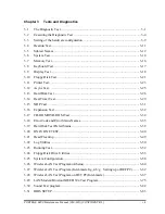
Page 107: ... CONFIDENTIAL Chapter 3 Tests and Diagnostics ...

Page 108: ...3 Tests and Diagnostics 3 ii CONFIDENTIAL PORTEGE R500 Maintenance Manual 960 634 3 ...

Page 109: ...2 3 Heatrun test program 3 8 3 3 Setting of the hardware configuration 3 9 3 4 Heatrun Test 3 11 3 5 Subtest Names 3 12 3 6 System Test 3 14 3 7 Memory Test 3 16 3 8 Keyboard Test 3 17 3 9 Display Test 3 18 3 10 Floppy Disk Test 3 21 3 11 Printer Test 3 23 3 12 Async Test 3 25 3 13 Hard Disk Test 3 26 3 14 Real Timer Test 3 29 3 15 NDP Test 3 31 3 16 Expansion Test 3 32 3 17 CD ROM DVD ROM Test 3 ...

Page 110: ...58 3 25 1 Function Description 3 58 3 25 2 Operations 3 59 3 26 Wireless LAN Test Program Athetos 3 60 3 27 Wireless LAN Test Program Intel made b g a b g Setting up of REF PC 3 62 3 28 Wireless LAN Test Program on DUT PC Intel made 3 67 3 28 1 Wireless LAN Test Program Intel made Golan on DUT PC 3 67 3 28 1 Wireless LAN Test Program Intel made Kedron on DUT PC 3 71 3 29 LAN Modem Bluetooth IEEE13...

Page 111: ...R500 Maintenance Manual 960 634 CONFIDENTIAL 3 v Tables Table 3 1 Subtest names 3 12 Table 3 2 Error codes and error status names 3 35 Table 3 3 Hard disk controller status register contents 3 38 Table 3 4 Error register contents 3 39 ...

Page 112: ...3 Tests and Diagnostics 3 vi CONFIDENTIAL PORTEGE R500 Maintenance Manual 960 634 ...

Page 113: ...he computer It is also included in one of Diagnostic Disks The heatrun test is automatic test program which executes the some tests successively NOTE Before starting the diagnostics be sure to follow these steps 1 Check all cables are connected firmly 2 Exit any application and close Windows 3 Check if All Devices is selected in the Device Config in SETUP menu 3 1 1 Diagnostics menu The DIAGNOSTIC...

Page 114: ...Floppy disk test USB FDD for all tests A USB test module USB test A USB cable USB test An external CRT monitor Expansion test A CD test media TOSHIBA CD ROM TEST DISK or ABEX TEST CD ROM Sound test A DVD test media DVD ROM TEST DISK TSD 1 Sound test A music CD Sound test A store bought CD RW media CD ROM DVD ROM test A microphone Sound test Headphones Sound test A cleaning kit to clean the floppy ...

Page 115: ...ollowing programs Initial configuration DMI information save DMI information recovery System configuration display E2PROM test MAC GUID DMI You will need the following equipment to perform some of the programs The Diagnostics Disk Main T D 3 1 3 Heatrun test program The heatrun test starts automatically after the selection You will need the following equipment to perform this program The Diagnosti...

Page 116: ...se To start the Diagnostics menu T D press 1 Repair Main and press Enter To start the H W initial information setting tool press 2 Repair Initial config set and press Enter To start the Heatrun test press 3 Repair Heatrun and press Enter NOTE When replacing the system board it is necessary to execute the followings 1 Before replacing save the DMI information by executing subtest 03 DMI information...

Page 117: ... c copyright TOSHIBA Corp 20XX DIAGNOSTICS MENU 1 DIAGNOSTIC TEST 2 ONLY ONE TEST 3 4 HEAD CLEANING 5 LOG UTILITIES 6 RUNNING TEST 7 FDD UTILITIES 8 SYSTEM CONFIGURATION 9 POWER OFF 0 Exit to Repair menu NOTE To exit the DIAGNOSTIC TEST MENU press the Esc key If a test program is in progress press Ctrl Break to exit the test program If a test program is in progress press Ctrl C to stop the test pr...

Page 118: ...6 PRINTER TEST It is not supported 7 ASYNC TEST It is not supported 8 HARD DISK TEST 9 REAL TIMER TEST 10 NDP TEST 11 EXPANSION TEST 12 CD ROM DVD ROM TEST 88 ERROR RETRY COUNT SET FDD HDD 99 EXIT TO DIAGNOSTICS MENU Functions 1 through 12 are the Diagnostic Tests Function 88 sets the floppy disk drive and hard disk drive error retry count 0 255 To exit the submenu of the Diagnostic Test and retur...

Page 119: ...ayed by your computer may be slightly different from the one shown above Select the desired subtest number from the subtest menu and press Enter The following message will appear TEST LOOP YES or NO ERROR STOP YES or NO Use the right and left arrow keys to move the cursor to the desired option Selecting YES of TEST LOOP increases the pass counter by one each time the test cycle ends and restarts t...

Page 120: ...or counter Table 3 1 in section 3 5 describes the function of each test on the subtest Table 3 2 in section 3 18 describes the error codes and error status names for each error Details of tests in DIAGNOSTIC TEST MENU are described on and after section 3 6 As for other service programs refer to section 3 20 to 3 25 3 2 2 H W initial information setting tool After selecting this test the following ...

Page 121: ...lem the program executes the item again Setting of the CPU set table Setting of the micro code Setting of the EHSS Inputting and writing of DMI information When the DMI information is displayed the following messages appear in order Input each information If you do not replace the PCB the DMI information should not be changed 1 Enter Model Name is displayed Input the computer s model name and pres...

Page 122: ...ubtest saves all the DMI data in a floppy disk Subtest 3 DMI information recovery This is one of tools to copy the DMI information to a new PCB after replacing This subtest writes all the DMI data in the floppy disk into the new PCB NOTE Since the data of UUID is updated every time when this subtest DMI information recovery is done the saved UUID data is not written Subtest 4 System configuration ...

Page 123: ...3 Running Test are executed successively For more details on the procedure and test content refer to Running Test When the heatrun test ends normally following message appears in the display HEATRUN NORMAL END Press any key to continue Press any key and return to the startup menu NOTE The test result Errorlog txt is stored in the floppy disk The result is displayed in the same format as Log Utilit...

Page 124: ...eyserville Quick charge DMI read 2 MEMORY 01 02 03 04 Conventional memory Protected Mode Cache memory on off Stress 3 KEYBOARD 01 Pressed key code display 4 DISPLAY 01 02 03 04 05 06 07 08 09 VRAM read write for VGA Gradation for VGA Gradation for LCD Gradation Mode test for VGA All dot on off for LCD H pattern display LCD Brightness LCD EDID Information External EDID read compare 5 FLOPPY DISK 01...

Page 125: ... to point receive Wraparound board 8 HARD DISK 01 02 03 04 05 06 07 08 09 Sequential read Address uniqueness Random address data Cross talk peak shift Partial Read Write specified address Read specified address Sequential write W R C specified address 9 REAL TIMER 01 02 03 Real time Backup memory Real time carry 10 NDP 01 NDP 11 EXPANSION 01 02 PCMCIA wraparound Not supported RGB monitor ID 12 CD ...

Page 126: ...0 FAN 1 2 To check the CPU fan press 1 and Enter To check the GPU fan press 2 and Enter To check both CPU fan and GPU fan press 0 and Enter The following message will appear Test Fan Revolution 0000RPM start Make sure the fan does not rotate then press Enter The following message will appear Test Fan Revolution Low speed Start Make sure the fan rotates at low speed then press Enter The following m...

Page 127: ...read This subtest displays the information in the Flash ROM in the following format DMI Data Display Ver X XX Model Name XXXXXXXXXXX Version Number XXXXXXXXXXXX Serial Number XXXXXXXX Model Number XXXXXX XXXXX PCN BND number XXXXXXXXXXXXXXXXXXXXXXXXXXXXXXXX UUID Number XXXXXXXXXXXXXXXXXXXXXXXXXXXXXXXX Press Enter to EXIT To exit this subtest and return to the SYSTEM test menu press Enter ...

Page 128: ...YS file This subtest writes constant data and address data from 1MB to maximum MB and reads the new data and compares the result with the original data Subtest 03 Cache memory on off To test the cache memory a pass through write read comparison of 5Ah data is run repeatedly to the test area 7000 Program size to 7000 7FFF 32 KB to check the hit miss ratio on off status for CPU cache memory One test...

Page 129: ...btest 01 Pressed key code display When a key is pressed the scan code character code and key top name are displayed on the screen in the format shown below The Ins Lock Caps Lock Num Lock Scroll Lock Alt Ctrl Left Shift and Right Shift keys are displayed in reverse screen mode when pressed The scan codes character codes and key top names are shown in Appendix E KEYBOARD TEST IN PROGRESS 302000 Sca...

Page 130: ...02 Gradation for VGA This subtest displays four colors red green blue and white from left to right across the screen from black to maximum brightness The display below appears on the screen when this subtest is executed To exit this subtest and return to the DISPLAY TEST menu press Enter Subtest 03 Gradation for LCD This subtest displays bands of gradations for mixed colors then for red green and ...

Page 131: ...4 768 64K Mode 118 1024 768 16M The display below appears on the screen when this subtest is executed Display example Mode 12 To exit this subtest and return to the DISPLAY TEST menu press Enter after displaying the Mode 118 Subtest 05 All dot on off for LCD This subtest displays an all white screen then an all black screen The display changes automatically every three seconds and the screen retur...

Page 132: ...HHHHHHHHHHHHHHHHHHHHHHH HHHHHHHHHHHHHHHHHHHHHHHHHHHHHHHHHHHHHHHHHHHHHHHHHH HHHHHHHHHHHHHHHHHHHHHHHHHHHHHHHHHHHHHHHHHHHHHHHHHH HHHHHHHHHHHHHHHHHHHHHHHHHHHHHHHHHHHHHHHHHHHHHHHHHH HHHHHHHHHHHHHHHHHHHHHHHHHHHHHHHHHHHHHHHHHHHHHHHHHH HHHHHHHHHHHHHHHHHHHHHHHHHHHHHHHHHHHHHHHHHHHHHHHHHH HHHHHHHHHHHHHHHHHHHHHHHHHHHHHHHHHHHHHHHHHHHHHHHHHH HHHHHHHHHHHHHHHHHHHHHHHHHHHHHHHHHHHHHHHHHHHHHHHHHH To exit this subtes...

Page 133: ...t the media mode and start track to be tested and press Enter Test start track Enter 0 dd 00 79 2 The Floppy Disk test contains five subtests that test the FDD The floppy disk test menu will appear after you select FDD test parameters FLOPPY DISK XXXXXXX XXX DIAGNOSTIC TEST VX XX Ctrl Break test end Ctrl C key stop SUB TEST XX PASS COUNT XXXXX ERROR COUNT XXXXX WRITE DATA XX READ DATA XX ADDRESS X...

Page 134: ...t 04 only Track No Head No Subtest 01 Sequential read This subtest performs a Cyclic Redundancy Check CRC that continuously reads all the tracks track 0 to 39 0 to 79 on a floppy disk Subtest 02 Sequential read write This subtest continuously writes data pattern B5ADADh to all the tracks track 0 to 39 0 to 79 on a floppy disk The data is then read and compared to the original data Subtest 03 Rando...

Page 135: ...lowing message will appear after selecting the subtest 01 to 03 of the printer test channel 1 XXXXh channel 2 XXXXh channel 3 XXXXh Select the channel number 1 3 The printer I O port address is specified by the XXXXh number The computer supports three printer channels Select the printer channel number and press Enter to execute the selected subtest Subtest 01 Ripple pattern This subtest prints cha...

Page 136: ...t This subtest prints the various print types shown below Subtest 03 Wraparound NOTE To execute this subtest a printer wraparound connector must be connected to the computer s printer port This subtest checks the output and bi directional modes of the data control and status lines through the parallel port wraparound connector 34M741986G01 Both output and bi directional modes are tested 3 24 CONFI...

Page 137: ... 7Eh Subtest 01 FIR SIR point to point send NOTE To execute subtests 01 and 02 each computer must have access to the other computer s infrared port This subtest sends 20h through 7Eh data to the receive side then receives the sent data and compares it to the original data through the FIR SIR port Subtest 02 FIR SIR point to point receive This subtest is used with subtest 01 described above This su...

Page 138: ...reate back up disks as described below Check to see if the Microsoft Create System Disks Tools MSCSD EXE still exists in the System Tools Folder This tool can be used only once If it exists use it to back up the pre installed software then use the Backup utility in the System Tools folder to back up the entire disk including the user s files Refer to the operating system instructions 1 The followi...

Page 139: ...r The first digit of the STATUS indicates the drive being tested and the last two digits indicate the error status code as explained in the table 3 2 of the section 3 18 Subtest 01 Sequential read This subtest is a sequential reading of all the tracks on the HDD starting at track 0 When all the tracks on the HDD have been read the test starts at the maximum track and reads the tracks on the HDD se...

Page 140: ...inder 2DB6DB 6 cylinder D24974 7 cylinder Subtest 05 Partial Read This subtest reads 1GB data which is in minimum middle and maximum address of the HDD area Subtest 06 Write specified address This subtest writes specified data to a specified cylinder and head on the HDD Subtest 07 Read specified address This subtest reads data which has been written to a specified cylinder and head on the HDD Subt...

Page 141: ... new date PRESS ENTER KEY TO EXIT TEST 2 If the current date is not correct input the correct date at the Enter new date prompt and press Enter 3 The following messages will appear Current date XX XX XXXX Current time XX XX XX Enter new time PRESS ENTER KEY TO EXIT TEST 4 If the current time is not correct input the correct time in 24 hour format To enter press Shift The time is updated To exit th...

Page 142: ...nt date and time are erased This subtest checks the real time clock increments making sure the date and time are displayed in the following format Current date 12 31 1999 Current time 23 59 58 The real time increments are automatically executed and the following is displayed Current date 01 01 2000 Current time 00 00 00 PRESS Enter KEY TO EXIT TEST To exit the test press Enter ...

Page 143: ...960 634 CONFIDENTIAL 3 31 3 15 NDP Test To execute the NDP test select 10 from the DIAGNOSTICS TEST MENU press Enter and follow the directions on the screen Subtest 01 NDP This test checks the following functions of NDP Control word Status word Bus Addition Multiplication ...

Page 144: ...d wraparound connector is required This subtest checks the following signal line of the PC card slot Address line REG CE 1 CE 2 line Data line Speaker line Wait line BSY BVD1 line This subtest is executed in the following order Sub Address Good Bad Contents 01 00001 00001 nn nn xx xx Address line REG CE 1 CE 2 nn A0 90 80 00 02 00002 ww rr Data line ww write data rr read data 03 00003 Speaker line...

Page 145: ... monitor with monitor ID function is required Connect the external monitor to the PC for the test of ID acquisition The judgment of acquisition is based on the panel data In simultaneous display mode or internal display mode in which the panel data is acquired this subtest will fail Therefore make sure only the external display is selected when executing this subtest ...

Page 146: ...GE R500 Maintenance Manual 960 634 3 17 CD ROM DVD ROM Test NOTE CD ROM DVD ROM Test can be performed only when the DIAGNOSTIC PROGRAM is started from the CD ROM Subtest 01 Sequential read This subtest is a sequential reading of one block units of all the logical addresses ...

Page 147: ...AC ADAPT ROM SENSING ERROR 1st Batt ROM SENSING ERROR 2nd Batt ROM THORMISTOR ERROR 1 ROM THORMISTOR ERROR 2 ROM THORMISTOR ERROR 3 Memory 01 02 DD RAM PARITY ERROR RAM PROTECTED MODE NO CHANGE RAM CACHE MEMORY ERROR Keyboard FE FD F0 F1 F2 F3 F4 F5 F6 F7 F8 F9 FA EF ED USB GET DESCR ERROR FIRST USB SET ADDRESS ERROR HUB GET DESCR ERROR Top 8B HUB GET DESCR ERROR Whole HUB SET CONFIGURATION ERROR ...

Page 148: ...0 PRT TIME OUT PRT FAULT PRT SELECT LINE PRT OUT OF PAPER PRT POWER OFF PRT BUSY LINE ASYNC 01 02 04 08 10 20 40 80 88 05 06 RS232C DTR ON TIME OUT RS232C CTS ON TIME OUT RS232C RX READY TIME OUT RS232C TX FULL TIME OUT RS232C PARITY ERROR RS232C FRAMING ERROR RS232C OVERRUN ERROR RS232C LINE STATUS ERROR RS232C MODEM STATUS ERROR SIR TIME OUT ERROR FIR TIME OUT ERROR HDD 05 07 09 0B BB 08 01 02 0...

Page 149: ... PROCESSOR NDP CONTROL WORD ERROR NDP STATUS WORD ERROR NDP BUS ERROR NDP ADDITION ERROR NDP MULTIPLAY ERROR EXPANSION C1 C3 C4 C5 C6 C7 C8 CB CC CE CF ADDRESS LINE ERROR CE 1 LINE ERROR CE 2 LINE ERROR DATA LINE ERROR WAIT LINE ERROR BSY LINE ERROR BVD1 LINE ERROR ZV Port ERROR NO PCMCIA CARD TYPE ERROR ZV_CONT ERROR CD ROM DVD ROM 01 02 03 04 05 06 09 11 20 40 80 90 B0 BAD COMMAND ILLEGAL LENGTH...

Page 150: ...e displays the HDC error register The contents of the HDC status register and error register are listed in Tables 3 3 and 3 4 Table 3 3 Hard disk controller status register contents Bit Name Description 7 BSY Busy 0 HDC is ready 1 HDC is busy 6 DRY Drive ready 0 Hard disk drive is not ready to accept any command 1 Hard disk drive is ready 5 DWF Drive write fault 0 DWF error is not detected 1 Write...

Page 151: ...etected 6 UNC Uncorrectable 0 There is no uncorrectable data error 1 Uncorrectable data error has been detected 5 Not used 4 IDN Identification 0 Not used 1 There is no ID field in the requested sector 3 Not used 2 ABT Abort 0 Not used 1 Illegal command error or command abort 1 TK0 Track 0 0 The hard disk found track 0 during a recalibrate command 1 The hard disk could not find track 0 during a re...

Page 152: ...est 2 from the DIAGNOSTIC MENU and press Enter The following menu appears in the display ONLY ONE TEST Menu XXXXXXXXX 1 Pressed Key Display 2 Touch Pad 3 Wireless communication switch 4 USB Port Select menu 5 LED 6 Button 7 Acceleration sensor 8 Docker Dock Undock 9 Exit to Common Test Press test number 1 8 9 Select the subtest number you want to test and press Enter To return to the Common Test m...

Page 153: ...key is pressed the corresponding key on the screen changes to the key character that was pressed Holding a key down enables the auto repeat function that causes the key s display character to blink Press Del Enter to end the test NOTE The actual display may be different from the above image according to the model PORTEGE R500 Maintenance Manual 960 634 CONFIDENTIAL 3 41 ...

Page 154: ...ch When moving your finger on the touch pad towards the upper left the POINTING display changes according to the following illustration If a touch pad switch is pressed the BUTTONS displays appear on the right side one by one The parameters appear above the BUTTONS 1 or 2 corresponding to the pressed touch pad switch highlights To end this subtest press two touch pad switches at the same time 3 42...

Page 155: ...on switch OFF After Sliding the switch to OFF position return to the ONLY ONE TEST menu automatically Subtest 4 USB Port Select menu NOTE When executing this subtest USB test module and USB cable must be connected This subtest checks if USB port works properly The following menu appears in the display Port Select menu 0 Port 0 Right side 1 Port 1 Left side back 2 Port 2 Left side front 9 Exit Pres...

Page 156: ...D test Press any key and following message appears in the display Caps Num Overlay BT W LAN LED test 1 Press Caps Lock key Caps on off 2 Press Fn F10 key Arrow on off 3 Press Fn F11 key Num on off 4 Slide BT W LAN switch L R on off Confirm corresponding LED lights properly Press Enter and following message appears in the display Check DC IN Power Main Battery LED Green Check if the color of the me...

Page 157: ...ay if the test ends without an error Press any key return to each Steps if NG or Press any key message apprears Press the Toshiba Presentation button after the following message appears Step2 X 1 2 Press Function button Back light On Off button OK message appears in the display if the test ends without an error Press any key return to each Steps if NG or Press any key message apprears If the test ...

Page 158: ... desk with vertical plane to get the stability of machine 2 The vertical wall or plane is necessary 3 Prevent the machine from shake or shock Vertical plane Flat desk Set the machine against the vertical plane with the Front upward Example The figure below shows the name and position of each side 3 46 CONFIDENTIAL PORTEGE R500 Maintenance Manual 960 634 Right side Left side Back Front Top heaven s...

Page 159: ...at desk with the right side of machine upward Then press Enter to detect the data on this setting of machine The following message appears in the display The front establishes in the upper direction Press Enter key Set the machine against the vertical plane on the flat desk with the front of machine upward Then press Enter to detect the data on this setting of machine The following message appears...

Page 160: ...Slim Port Replicator II the following message appears Pushing Eject SW and press Enter Key Press Enter without pushing the eject button of the Slim Port Replicator II after the following message appears Release Eject SW and press Enter Key If the test ends successfully the display returns to the ONLY ONE TEST menu When the display returns to the ONLY ONE TEST menu remove the Express Port Replicato...

Page 161: ...rform this program 3 21 2 Operations 1 Selecting test 4 from the DIAGNOSTIC MENU and pressing Enter displays the following messages DIAGNOSTICS FLOPPY DISK HEAD CLEANING VX XX Mount cleaning disk s on drive s Press any key when ready 2 Remove the Diagnostics Disk from the FDD then insert the cleaning disk and press Enter 3 When the cleaning start message appears the FDD head cleaning has begun 4 T...

Page 162: ...nnect USB FDD when you perform the DIAGNOSTIC PROGRAM from the CD ROM The data is stored in floppy disk The error information is displayed in the following order 1 Error count CNT 2 Test name Subtest number TS No 3 Pass count PASS 4 Error status STS 5 FDD HDD or memory address ADDR 6 Write data WD 7 Read data RD 8 HDC status HSTS 9 Error status name ERROR STATUS NAME If the power switch is turned ...

Page 163: ... Clear 5 Print 6 FD Log Read 7 FD Log Write 2 The error information displayed on the screen can be manipulated by the following number keys The 1 key scrolls the display to the next page The 2 key scrolls the display to the previous page The 3 key returns to the Diagnostic Menu The 4 key erases all error log information in RAM The 5 key outputs the error log information to a printer The 6 key read...

Page 164: ...g test pull out the test program and insert a floppy disk which has been formatted by FORMAT command of DOS 1 Pull out the test program and insert a floppy disk which has been formatted by FORMAT command of DOS 2 Select 6 from the DIAGNOSTIC MENU and press Enter the following messages for selectable tests will appear in the display in order FDD write read test Y N Printer wrap around test Y N Seri...

Page 165: ...om the Toshiba DOS FORMAT command This program can format a floppy disk in the following formats a 2DD Double sided double density double track 96 135 TPI MFM mode 512 bytes 9 sectors track b 2HD Double sided high density double track 96 135 TPI MFM mode 512 bytes 18 sectors track 2 COPY This program copies data from a source floppy disk to a target floppy disk 3 DUMP This program displays the con...

Page 166: ...ing message Type select 0 2DD 3 2HD c Select a media drive type number and press Enter A message similar to the one below will be displayed Warning Disk data will be destroyed Insert work disk into drive A Press any key when ready d Remove the Diagnostics Disk from the FDD insert the work disk and press any key The following message will be displayed when the FDD format is executed FDD TYPE TRACK ...

Page 167: ... has started FDD TYPE TRACK XXX FDD TYPE HEAD X FDD TYPE SECTOR XX Copy start track head XXX X d The following message will appear Insert target disk into drive A Press any key when ready e Remove the source disk from the FDD then insert a formatted work disk and press any key The following message will appear and start copying to the target disk track head XXX X f When the amount of data is too l...

Page 168: ...ng message will appear Select a media mode 2HD media mode 1 1 20MB 2 1 44MB 3 1 23MB e The following message will appear Insert source disk into drive A Press any key when ready f Insert a source disk and press any key and the following message will appear Max address Track XXXX Head XX Sector XX Track number g Set the track number head number and sector number you want to dump The system will acc...

Page 169: ...finish the dump select 3 Press number key 1 up 2 down 3 end l The following message will appear Selecting 2 returns to the FDD UTILITIES MENU Another dump 1 Yes 2 No 5 HDD ID READ program Selecting HDD ID displays the following HDD ID configuration HDD ID Read VX XX Drive 1 Model No XXXXXXX Press Enter key Press Enter to return to the FDD UTILITIES MENU ...

Page 170: ...nnot be acquired The System Configuration program contains the following configuration information for the computer 1 Processor Type Code L2 cache 2 Chip set VRAM 3 BIOS ROM version 1st ID 2nd ID 4 Boot ROM version 5 EC total version 6 PS Microprocessor version 7 SVP Par version 8 Microcode Revision 9 Total Memory Size Conventional memory 10 Battery code 11 HWSC 12 FSB Voltage 13 Printer Adapter 1...

Page 171: ...on Version VX XX SVP Par Version VX XX Panel XXXX XXXX Menu XXXX Prod XXXX Microcode Revision VX XX Processor XXXh Total Memory Size XXXXXXMB Conventional Memory XXXKB Battery Code XXXXXXXXXXXX Present voltage XXXX HWSC XXXXXXX FSB XXXXXMHz Voltage XXh X Printer Adapter LPT1 XXXX LPT2 XXXX LPT3 XXXX X ASYNC Adapter COM1 XXXX COM2 XXXX COM3 XXXX X Math CO Processor X Floppy Disk Drive s Track XX He...

Page 172: ...nnection by using Windows programs Check of the wireless LAN card type 1 Slide the wireless communication switch to ON position 2 Check the card type according to the following procedure Click Start All Programs TOSHIBA Utilities PC Diagnostic Tool Check the Network If the Atheros AR5006EG 11b g or Atheros AR5006EX 11a b g is shown the correct card is installed in the computer 3 60 CONFIDENTIAL PO...

Page 173: ...he computer finds any AP Access Point the antenna marks like as follows will appear It shows the antenna cables are surely connected to the wireless LAN card 3 The following message will appear if the antenna cables are not connected to the wireless LAN card or no available access point is found In this case check the antenna cable connection to the wireless LAN card by disassembling the computer ...

Page 174: ... 11a 11aAP AP for check of 11b 11bAP AP for check of 11g 11gAP Make the security functions of AP WEP WPA etc invalid REF Reference PC Cross cable DUT Device Under Testing DUT Device Under Testing REF Reference PC 11a b g AP Cross cable Configuration of equipment for transmitting receiving test How to setup the REF PC Set up the wireless LAN environment needed for the test before the start of Respo...

Page 175: ...ostics 2 Open My Computer window and click My Network places on the left column 3 Click View network connections on the left column 4 The Network Connections window appears Double click Local Area Connection Network Connections window PORTEGE R500 Maintenance Manual 960 634 CONFIDENTIAL 3 63 ...

Page 176: ...Connection Properties window Local Area Connection Properties window 6 Select Protocol on the Select Network Component Type window and click Add button Select Network Component Type window 7 Click Have Disk button on the Select Network Protocol window Select Network Protocol window 3 64 CONFIDENTIAL PORTEGE R500 Maintenance Manual 960 634 ...

Page 177: ...window 9 The Select Network Protocol window appears again In the Network Protocol DDK PACKET Protocol will appear Then click OK to start the installation Select Network Protocol window 10 When the installation is completed Local Area Connection Properties will appear Confirm that the DDK PACKET Protocol is added Click Close button to finish the setup of REF PC Local Area Connection Properties wind...

Page 178: ...m DUT via AP OS available Windows XP only How to start Double click WTWINSVR icon How to start 1 Double click wtwinsvr icon The following screen will appear Startup screen of wtwinsvr program 2 Enter the number of Network Adapter used on REF PC enter 1 for example above Then the following screen will appear Start the test program on DUT Screen while running the wtwinsvr program The REF PC is waiti...

Page 179: ...ng U The following menu appears in the display Intel PRO Wireless XXXABG Network Connection Maintenance T D Menu 1 SKU check of Module 2 MAC Address Check 3 Antenna Check communication test of 11b mode 4 Communication test of 11a mode 5 Communication test of 11g mode 6 All the tests of 11a b g Card SKU MAC Check 11a b g communication test SELECT TEST No 1 6 To execute the subtest input the subtest...

Page 180: ...d Checking the connection execute the subtest again Subtest02 MAC Address Check This subtest displays the MAC address Selecting this subtest following message will appear in the display MAC CHECK MAC XXXXXXXXXXXX MAC Address Check OK Press any key and return to the test menu If a defective is found during the test following message will appear in the display MAC CHECK ERROR MAC all F MAC XXXXXXXXX...

Page 181: ...ng any key the following message which antenna is defective is displayed Main Antenna Test NG Aux Antenna Test NG Press any key and return to the test menu Subtest04 Communication test of 11a mode This subtest execute transmitting receiving test in 802 11a mode using the main antenna If a defective is not found during the test OK message will appear in the display Press any key and return to the t...

Page 182: ...g the test NG message will appear in the display When pressing any key the following message is displayed 11g Communication Test NG When a defective is detected in the test following typical cause is considered Connection of wireless LAN card Defective wireless LAN card Disappearance of MAC address data Checking the connection execute the subtest again Subtest06 All the tests of 11a b g Card All t...

Page 183: ...Connection Maintenance T D Menu 1 SKU check of Module 2 MAC Address Check 3 Communication test of 11a mode 4 Communication test of 11b mode 5 Communication test of 11g mode 6 All the tests of Wireless WiFi Link 4965 Module SKU MAC Check communication test SELECT TEST No 1 6 To execute the subtest input the subtest number and press Enter Subtest01 SKU check of module This subtest displays SKU infor...

Page 184: ...This subtest displays the MAC address Selecting this subtest following message will appear in the display MAC CHECK MAC XXXXXXXXXXXX MAC Address Check OK Press any key and return to the test menu If a defective is found during the test following message will appear in the display MAC CHECK ERROR MAC all F MAC XXXXXXXXXXXX MAC Address Check NG Press any key and return to the test menu When a defect...

Page 185: ...red Connection of wireless LAN card Defective wireless LAN card Disappearance of MAC address data Checking the connection execute the subtest again Subtest04 Communication test of 11b mode This subtest execute transmitting receiving test in 802 11a mode using the main antenna If a defective is not found during the test OK message will appear in the display Press any key and return to the test menu...

Page 186: ...t NG message will appear in the display When pressing any key the following message is displayed 11g Communication Test NG When a defective is detected in the test following typical cause is considered Connection of wireless LAN card Defective wireless LAN card Disappearance of MAC address data Checking the connection execute the subtest again Subtest06 All the tests of Wireless WiFi Link 4965 Mod...

Page 187: ...ower The following message will appear Microsoft Windows XX Startup Menu 1 LAN 2 Modem Not used 3 Bluetooth 4 IEEE1394 Enter a choice Press the number you want to test and press Enter NOTE It is impossible to go back to startup menu once you choose the test Therefore LAN Modem Bluetooth IEEE1394 test can not be executed successively 3 29 1 LAN test To execute LAN test press 1 and Enter The followi...

Page 188: ...t receive test COMPLETED Repeat count 00000 Error count 00000 LOOPBACK TEST 100Mbps Auto negotiation TxRx Test Destination Address xxxxxxxxxxxx Source Address xxxxxxxxxxxx 100Base TX Full Duplex TRANSMIT RECEIVE NOTE The menu displayed by your computer may be slightly different from the one shown above If a defective is found NG message will appear in the display 3 76 CONFIDENTIAL PORTEGE R500 Mai...

Page 189: ... Testing adaptor hit ESC to abort External Loopback Test PASSED Testing completed Loopback Test Complete 1000Base Auto negotiation TxRx Test CE Test Complete NOTE The menu displayed by your computer may be slightly different from the one shown above If a defective is found NG message will appear in the display Subtest03 Marvel NOTE This Subtest is not supported in this computer PORTEGE R500 Mainte...

Page 190: ... 1 ICHx 2 ICH6 Press test number 1 2 To execute Modem test press 2 and Enter Following message will appear Modem loopback test ICHx MDC Test Program with Modem Sound Line Test Version X X Scorpio Modem Initialize OK Digital Loopback Test OK RJ11 Connector Check LED Operator s Check OK is displayed when a error is detected NG is display when a error is not detected NOTE The menu displayed by your c...

Page 191: ...is also available A Bluetooth card should be installed on the target computer Install the Bluetooth function by clicking All Programs TOSHIBA Bluetooth Bluetooth Settings Test procedure 1 Enable the Bluetooth function of the responder device 2 Make sure the wireless communication switch of the target computer is set to ON position 3 Right click the Bluetooth icon on the lower right screen of the t...

Page 192: ...h address of the responder device appears the Bluetooth card and antenna connection are OK If the BT address of the responder device does not appear check the Bluetooth card condition and antenna cable connection to the Bluetooth card by disassembling the computer following the steps described in Chapter 4 Replacement Procedures 3 80 CONFIDENTIAL PORTEGE R500 Maintenance Manual 960 634 ...

Page 193: ...ecute the TEST select the test number you want to execute and press Enter Subtest01 Transmit Receive test NOTE Before executing subtest 01 be sure to execute subtest 02 in the responder machine This program checks the data transporting between responder machine and target machine and compare them with the original data through the IEEE1394 cable Subtest 02 Responder set This program is executed in...

Page 194: ...al 960 634 CONFIDENTIAL 3 82 3 30 Sound Test program Sound TEST disk cannot be used in PORTEGE R500 Therefore please test the sound on Windows OS 1 Play a music file 2 click TOSHIBA utility PC diagnostic tool to test the sound Please check operation of speakers by one of methods ...

Page 195: ...rvisor Password 4 HDD Password a HDD b HDD Password Mode c User Password d Master Password 5 Boot Priority a Boot Priority b HDD Priority 6 Others a Core Multi Processing b Dynamic CPU Frequency Mode c Execute Disable Bit Capability d Auto Power On e Performance Battery Life Setting f Beep Volume g Diagnostic Mode h USB Sleep and Charge 7 Configuration 8 Battery a Battery Save Mode b PCI Express L...

Page 196: ...s 11 Security Controlle a TPM b Clear TPM Owner 12 Display a Power On Display b LCD Display Stretch c Multi Field Driving 13 Peripheral a Internal Pointing Device 14 Legacy Emulation a USB KB Mouse Legacy Emulation b USB FDD Legacy Emulation c USB Memory BIOS Support 15 PCI LAN a Built in LAN b Wireless LAN ...

Page 197: ...turn on the power Then press F1 The following display appears 1 In the case of a model with built in 1 1 8 type HDD it is displayed as follows Primary IDE 1F0H IRQ14 2 In the case of a model with built in 1 8 type HDD it is not displayed PORTEGE R500 Maintenance Manual 960 634 CONFIDENTIAL 3 85 ...

Page 198: ...hanged item requires the system to reboot the following message is displayed Are you sure Y N The changes you made will cause the system to reboot 2 To make other changes press N Repeat the steps above 3 To accept the changes press Y NOTE You can press Esc to quit at any time without saving changes SETUP asks you to confirm that you do not want to save your changes When SETUP is displayed at the n...

Page 199: ... Password This option allows you to set or reset the user password for power on Registered A password has been registered Not Registered Change or remove the password Default a Supervisor Password This setting which is displayed on the first page of the setup screen allows you to register a Supervisor Password of the computer Registered Supervisor Password has been registered Not Registered Superv...

Page 200: ...password Mode For details refer to the User s Manual 5 Boot Priority a Boot Priority Use this option to set the priority for booting of the computer and the priority for the HDD for booting HDD FDD CD ROM LAN The computer looks for bootable files in the following order HDD FDD CD ROM and LAN Default FDD HDD CD ROM LAN The computer looks for bootable files in the following order FDD HDD CD ROM and ...

Page 201: ...g is carried out in the BIOS setup program Enabled is Dual Core mode Disabled is Single Core mode Enabled Enables Core Multi Processing functions Default Disabled Disables Core Multi Processing functions b Dynamic CPU Frequency mode Use this option to choose a setting from the followings Dynamically Switchable Enables Intel CoreTM Duo processor featuring Intel SpeedStep technology Default Always H...

Page 202: ...or the Auto Power On automatic power on function and the Wake up on LAN in the OPTIONS window To set the time use Space or BackSpace Press to move the cursor to the right and to move the cursor to the left when you set the date and time For the Alarm Time set the time to turn on the power automatically The second cannot be set When it is set to Disabled the time to turn on automatically is not set...

Page 203: ...trolled by changing the memory bus frequency Battery Life Setting the memory bus frequency to 400MHz will give priority to battery operating time over computer processing power Performance Setting the memory bus frequency to 533MHz will give priority to computer processing power over battery operating time Default c Beep Volume This Option sets up the volume of a Beep sound Medium High OFF Low d D...

Page 204: ...lect Setup by OS 8 Battery a Battery Save Mode This option is used to select Full Power Low Power or User Setting of the battery save mode When you select the battery save mode the followings will appear Full Power The following shows full power settings Low Power The following shows low power settings NOTE Display of the LCD Brightness will be changed in the condition below 1 Operating the batter...

Page 205: ...ght Full brightness for high visibility Semi Bright Less than full brightness for saving power Cooling Method Maximum Performance If the CPU becomes too hot the fan turns on automatically in a high speed to cool down the CPU Performance If the CPU becomes too hot the fan turns on automatically When the CPU temperature falls to a normal range the fan turns off Battery optimized If the CPU becomes t...

Page 206: ...t lower the power consumption 9 Drives I O This option displays the address and interrupts level for hard disk drive and optical disk drive It is for information only and cannot be changed a Built in HDD This option displays the setting of the address and interrupt level of the HDD This cannot be changed b SATA Controller Mode This feature sets the SATA Controller Mode Note The SATA Controller Mod...

Page 207: ...ut this operation The procedure to follow is as detailed below 1 Move the cursor to the Clear TPM Owner setting and press either the Space key or BACK SPACE key 2 A message is displayed at which you should press the Y E S and ENTER keys in sequence the Trusted Platform Module information will then be erased 3 The Trusted Platform Module setting will then change from being Enable to Disabled and th...

Page 208: ...n of the computer s display panel Enabled This lowers the power consumption of the computer s display panel Disabled Disables Multi Field Driving feature Default This setting is recommended when playing the movies e g DVD Video 13 Peripheral Use this option to select the peripheral s mode a Internal Pointing Device This option enables or disables the touch pad Enabled Enables the touch pad Default...

Page 209: ...k is available without the driver Disabled Disables LEGACY support c USB Memory BIOS Support This Option sets up the format in which BIOS supports a USB memory HDD An HDD format is supported FDD An FDD format is supported 15 PCI LAN This option sets the Enable Disable of the built in LAN and Wireless LAN functions a Built in LAN Enabled Enables Built in LAN functions Default Disabled Disables Buil...

Page 210: ...3 Tests and Diagnostics 3 31 BIOS SETUP 3 98 CONFIDENTIAL PORTEGE R500 Maintenance Manual 960 634 ...

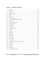
Page 211: ...Chapter 4 Replacement Procedures CONFIDENTIAL ...

Page 212: ...4 Replacement Procedures 4 ii CONFIDENTIAL PORTÉGÉ R500 Maintenance Manual 960 634 ...

Page 213: ...less LAN card 4 21 4 10 CPU fan assembly 4 23 4 11 RTC battery 4 26 4 12 DC IN jack 4 28 4 13 Bluetooth module 4 29 4 14 HDD SSD 4 31 4 14 1 2 5 HDD 4 32 4 14 2 1 8 HDD 4 33 4 14 3 SSD 4 35 4 15 Sound board Internal microphone 4 37 4 16 ODD SD board 4 39 4 17 USB board Switch unit 4 42 4 18 System board 4 45 4 19 Speaker 4 48 4 20 Display portion 4 50 4 21 Touch pad Fingerprint sensor board 4 54 4...

Page 214: ...assembly 4 23 Figure 4 13 Applying new grease 4 24 Figure 4 14 Removing the RTC battery 4 26 Figure 4 15 Removing the DC IN jack 4 28 Figure 4 16 Removing the Bluetooth module 4 29 Figure 4 17 Removing the 2 5 HDD 4 32 Figure 4 18 Removing the 1 8 HDD 4 33 Figure 4 19 Removing the SSD 4 35 Figure 4 20 Removing the sound board internal microphone 1 4 37 Figure 4 21 Removing the sound board internal...

Page 215: ...on 3 4 51 Figure 4 33 Removing the touch pad fingerprint sensor board 1 4 54 Figure 4 34 Removing the touch pad fingerprint sensor board 2 4 55 Figure 4 35 Removing the keyboard 4 57 Figure 4 36 Removing the LCD unit 1 4 59 Figure 4 37 Removing the LCD unit 2 4 60 Figure 4 38 Removing the wireless LAN antenna Bluetooth antenna 4 62 Figure 4 39 Removing the hinge 4 64 ...

Page 216: ...4 Replacement Procedures 4 vi CONFIDENTIAL PORTÉGÉ R500 Maintenance Manual 960 634 ...

Page 217: ... order to remove others The numbers in the chart indicate the relevant section numbers in this manual In all cases when removing the FRU the battery pack must also be removed When repairing the FRU that is the potential cause of a computer fault use the chart to determine the order in which FRUs need to be removed Refer to the example of the chart described below This chart shows which unit s you ...

Page 218: ...onnected from an AC power source Remove any metal jewelry or accessories such as necklaces bracelets or rings in order to reduce the risk of electric shock Never work with wet or damp hands 3 Be careful of edges and corners as these may cut CAUTION 1 When you change a component be sure the replacement component meets the required specifications Never use foreign parts to avoid any risk of damage t...

Page 219: ...which FRU is the cause of the fault 5 Do not perform any unnecessary work Always work in accordance with the disassembly and reassembly procedures in this manual 6 After removing parts from the computer place them in a safe place away from the computer so they will not be damaged and will not interfere with your work 7 You will remove and replace many screws when you disassemble the computer When ...

Page 220: ...the cable is disconnected from the connector reconnect it making sure that you lift the pressure plate high enough to insert fully the cable For spring connectors lift up the stopper frees the cable and allow it to be pulled out To reconnect hold the stopper in the up position and insert the cable then lower the stopper to secure the cable Pull the cable to ensure that it is securely connected For...

Page 221: ... secure all FRUs Using the wrong screw can either damage the threads on the screw or the head of the screw and may prevent proper seating of an FRU When using new parts with double side tapes peel off the separators After installing an FRU in the computer confirm that the FRU and the computer are functioning properly Tools and Equipment The use of Electrostatic Discharge ESD equipment is very impo...

Page 222: ... recommends that you use an electric screwdriver for quick and easy operations M2 2mm 0 167 N m 1 7 kgf cm M2 5 2 5mm 0 294 N m 3 0 kgf cm M3 3mm 0 549 N m 5 6 kgf cm NOTE To prevent damage to THIN HEAD screws use type 0 bit philips screwdriver Press along the axis of the screwdriver while turning the screw This is because the contact area between the screw and driver is less than for a pan head s...

Page 223: ...ch as 2 5 mm 2 6 mm and so on Grip area Screw Notation To make maintenance of the computer easier the types and lengths of the screws are indicated on the computer body and PCB Format Screw type Screw length mm Screw type B Bind screw F Flat head screw S Super thin head screw T Tapping screw U Other screws Unique screws pan head stud etc Example B6 6mm Bind screw Screw color material B Black Nicke...

Page 224: ...eak twist or bend the battery pack 1 Turn off the power of the computer 2 Disconnect the AC adapter and other external devices from the computer 3 Turn the computer face down 4 Release the battery lock Pull out the battery pack while sliding the battery latch as shown in the following figure Figure 4 1 Removing the battery pack Battery lock Battery pack Battery latch NOTE For environmental reasons...

Page 225: ...eplaced used handled or disposed of For environmental reasons collect the spent battery packs Use only batteries recommended by Toshiba for replacements NOTE Check the battery s terminals visually If they are dirty wipe them clean with a dry cloth 1 Turn off the power of the computer 2 Disconnect the AC adapter and all other external devices from the computer 3 Turn the computer face down 4 Instal...

Page 226: ...eject button for the PC card you want to remove to extend the button 2 Press the extended eject button to pop the PC card out 3 Grasp the PC card and pull it out Eject button PC card Figure 4 2 Removing the PC card Installing the PC card To install the PC card follow the steps below and refer to Figure 4 2 1 Make sure that the eject button is not extended 2 Insert the PC card into the card slot an...

Page 227: ...m documentation for proper procedures and precautions 1 Push the SD memory card in and release it to pop the card out 2 Grasp the SD memory card and pull it out SD memory card Figure 4 3 Removing the SD memory card Installing the SD memory card To install the SD memory card follow the steps below and refer to Figure 4 3 1 Insert the SD memory card in the card slot and push it carefully to ensure a...

Page 228: ...omputer itself Dust and stains on the connectors may cause memory access problems Never press hard or bend the memory module To remove the memory module make sure the computer is powered off follow the steps below and refer to Figure 4 4 and 4 5 1 Loosen the following screws and remove the memory cover M2 4B STEP screw 2 Memory cover M2 4B STEP Figure 4 4 Removing the memory module 1 4 12 CONFIDEN...

Page 229: ... outward to release them The memory module stands slantwise 3 Remove the memory module from the connector CN1460 on the system board Latch Memory module Latch CN1460 Figure 4 5 Removing the memory module 2 PORTÉGÉ R500 Maintenance Manual 960 634 CONFIDENTIAL 4 13 ...

Page 230: ...nto the connector CN1460 on the system board slantwise CAUTION Insert the dent of the memory module to the guide of the memory slot 2 Press down the memory module until it is latched firmly 3 Set the memory cover and secure it with the following screws M2 4B STEP screw 2 NOTE When the power of the computer is turned on the computer checks automatically the memory size Confirm that the new memory i...

Page 231: ...move the following screws securing the base cover assembly M2 4C S THIN HEAD screw 4 Described as A in the figure M2 6C S THIN HEAD screw 10 Described as B in the figure M2 5 6C S THIN HEAD screw 2 Described as C in the figure M2 2 4C S THIN HEAD screw 1 Described as D in the figure Base cover assembly Middle frame B B B B B B B C C A A A A D B B B LAN connector Figure 4 6 Removing the base cover ...

Page 232: ...e cover 3 Lift up the flip of the connector and disconnect the PC card cable from the connector CN2110 on the system board while holding the tab Tab Flip PC card cable CN2110 Figure 4 7 Removing the base cover assembly 2 4 16 CONFIDENTIAL PORTÉGÉ R500 Maintenance Manual 960 634 ...

Page 233: ... 4 6 to Figure 4 8 1 Set the base cover assembly in place 2 Secure the base cover assembly with the following screws M2 4C S THIN HEAD screw 4 Described as A in the figure M2 6C S THIN HEAD screw 10 Described as B in the figure M2 5 6C S THIN HEAD screw 2 Described as C in the figure M2 2 4C S THIN HEAD screw 1 Described as D in the figure 3 Connect the PC card cable to the connector CN2110 on the...

Page 234: ...gure 4 9 1 Turn over the base cover assembly 2 Remove the following screws securing the PC card slot M2 4C S THIN HEAD screw 2 M2 3C S THIN HEAD screw 2 3 Remove the PC card slot from the base cover assembly M2x4C S THIN HEAD M2x3C S THIN HEAD PC card slot Figure 4 9 Removing the PC card slot 4 18 CONFIDENTIAL PORTÉGÉ R500 Maintenance Manual 960 634 ...

Page 235: ...al 960 634 CONFIDENTIAL 4 19 Installing the PC card slot To install the PC card slot follow the steps below and refer to Figure 4 9 1 Set the PC card slot to the base cover assembly and secure it with the following screws M2 4C S THIN HEAD screw 2 M2 3C S THIN HEAD screw 2 ...

Page 236: ...ok Battery lock Battery latch Spring Figure 4 10 Removing the battery lock battery latch Installing the Battery lock Battery latch To install the battery lock battery latch follow the steps below and refer to Figure 4 10 1 Set push the battery lock battery latch to the base cover assembly from the bottom until the hooks are engaged CAUTION When installing the battery lock battery latch make sure t...

Page 237: ...m the wireless LAN card 2 Remove the following screws securing wireless LAN card M2 4C S THIN HEAD screw 2 3 Disconnect the wireless LAN card from the connector CN2600 on the system board M2 4C S THIN HEAD Wireless LAN card CN2600 Wireless LAN antenna cable three Wireless LAN antenna cable two Wireless LAN card CN2600 M2 4C S THIN HEAD Figure 4 11 Removing the wireless LAN card PORTÉGÉ R500 Mainte...

Page 238: ...the connector CN2600 on the system board slantwise and press it to connect firmly CAUTION Insert the dent of the wireless LAN card to the guide of the slot 2 Secure the wireless LAN card with the following screws M2 4C S THIN HEAD screw 2 3 Connect three or two wireless LAN antenna cables to the connectors on the wireless LAN card NOTE In the wireless LAN card that has three connectors connect the...

Page 239: ...fan assembly wipe the grease off of the bottom of the heat sink and top of the CPU Apply new grease when installing 1 Remove the following screws securing the CPU fan assembly M2 6C S THIN HEAD 2 2 Disconnect the fan cable from the connector CN8771 on the system board and remove the CPU fan assembly from the slot M2 6C S THIN HEAD CPU Fan assembly CN8771 Fan cable Figure 4 12 Removing the CPU Fan ...

Page 240: ...the CPU using a special syringe as shown in the following figure Apply new grease evenly on the CPU chip CAUTION Apply the silicon grease 0 2g 0 1mL Max to cover the chip surface using the special applicator Use a spatula to spread new grease The height of new grease shall not be over the height of the CPU chip 4 24 CONFIDENTIAL PORTÉGÉ R500 Maintenance Manual 960 634 Figure 4 13 Applying new grea...

Page 241: ...CN8771 on the system board 4 Set the CPU fan assembly to the slot and secure it with the following screws M2 6C S THIN HEAD 2 CAUTION Arrange the fan cable within the area indicated with the thick line in the figure below Fan cable PORTÉGÉ R500 Maintenance Manual 960 634 CONFIDENTIAL 4 25 ...

Page 242: ...fixed to the bottom of the RTC battery holder with a double sided tape and the cushion is fixed to the base cover with a double sided tape When removing the RTC battery holder be careful not to break the cushion of the bottom of the RTC battery holder 3 Open the RTC battery holder while peeling adhered portion with the double sided tape and remove the RTC battery from the RTC battery holder RTC ba...

Page 243: ...d tape CAUTION When the cushion of the bottom of the RTC battery holder is broken remove the broken cushion and set a new cushion to the double side tape on the RTC battery holder Cushion 2 Set stick the RTC battery holder in place 3 Connect the RTC battery cable to the connector CN9300 on the system board CAUTION Arrange the RTC battery cable not to be pinched by the HDD as shown in the figure be...

Page 244: ...ck from the slot Insulator DC IN jack DC IN jack cable Guide CN8800 Figure 4 15 Removing the DC IN jack Installing the DC IN jack To install the DC IN jack follow the steps below and refer to Figure 4 15 1 Set the DC IN jack into the guide of the slot and connect the DC IN jack cable to the connector CN8800 on the system board CAUTION When installing a new DC IN jack stick a new insulator in place...

Page 245: ...nnect the USB cable carefully from the connector CN9610 on the USB board 2 Disconnect the Bluetooth antenna cable and Bluetooth cable from the connector on the Bluetooth module 3 Remove the following screw and Bluetooth module M2 3C S THIN HEAD 1 Bluetooth module Bluetooth antenna cable Bluetooth cable USB cable M2x3C S THIN HEAD CN9610 Figure 4 16 Removing the Bluetooth module PORTÉGÉ R500 Mainte...

Page 246: ...s below and refer to Figure 4 16 1 Set the Bluetooth module to the slot and secure it with the following screw M2 3C S THIN HEAD 1 2 Connect the Bluetooth antenna cable and Bluetooth cable to the connector on the Bluetooth module 3 Connect the USB cable to the connector CN9610 on the USB board CAUTION When connecting the USB cable insert it carefully not to bend the connector portion ...

Page 247: ... stuck to the black shield layer Handle with care of installing removing 1 Do not use the 1 8 inch HDD cable SSD cable 2 5 inch HDD cable or SD cable which the black shield layer is peeled off When the black shield layer of the 1 8 inch HDD cable SSD cable 2 5 inch HDD cable and SD cable is peeled off orange or gray color will appear on the surface 2 Do not stick any tape except for the insulator ...

Page 248: ...ow 2 Disconnect the 2 5 HDD cable from the connector on the 2 5 HDD Connector of the 2 5 HDD 2 5 HDD 2 5 HDD cable Guide x4 Figure 4 17 Removing the 2 5 HDD Installing the 2 5 HDD To install the 2 5 HDD follow the steps below and refer to Figure 4 17 1 Connect the 2 5 HDD cable to the connector on the 2 5 HDD 2 Set the 2 5 HDD into the guides of the slot 4 32 CONFIDENTIAL PORTÉGÉ R500 Maintenance ...

Page 249: ...n the direction of the arrow in the figure below and remove four cushions from the 1 8 HDD 2 Disconnect the 1 8 HDD cable from the connector on the 1 8 HDD CAUTION The 1 8 inch HDD cable and SSD cable are the same Connector of the 1 8 HDD Figure 4 18 Removing the 1 8 HDD 1 8 HDD 1 8 HDD cable Guide x4 Cushion x4 PORTÉGÉ R500 Maintenance Manual 960 634 CONFIDENTIAL 4 33 ...

Page 250: ... four cushions to the 1 8 HDD 2 Turn over the 1 8 HDD and connect the 1 8 HDD cable to the connector on the 1 8 HDD 3 Turn the 1 8 HDD face up and set it into the guides of the slot CAUTION There are two types of system board for 2 5 HDD and 1 8 HDD When connecting the 1 8 HDD to the system board for 2 5 HDD the 1 8 HDD shall be broken Do not connect the 1 8 HDD to the system board for 2 5 HDD ...

Page 251: ...and SSD SSD cable is connected on the back of the SSD M1 4 3C S THIN HEAD 3 2 Disconnect the SSD cable from the connector on the SSD CAUTION The 1 8 inch HDD cable and SSD cable are the same Connector of the SSD On the back SSD M1 4x3C S THIN HEAD M1 4x3C S THIN HEAD SSD cable Figure 4 19 Removing the SSD PORTÉGÉ R500 Maintenance Manual 960 634 CONFIDENTIAL 4 35 ...

Page 252: ...GÉ R500 Maintenance Manual 960 634 Installing the SSD To install the SSD follow the steps below and refer to Figure 4 19 1 Connect the SSD cable to the connector on the SSD 2 Set the SSD into the slot and secure it with the following screws M1 4 3C S THIN HEAD 3 ...

Page 253: ...gure 4 20 and Figure 4 21 1 Remove the following screw securing the sound board M2 4C S THIN HEAD 1 2 Disconnect the sound cable and speaker cable from the connector CN9510 and CN6350 on the sound board and remove the sound board from the slot Speaker cable Sound cable Sound board M2x4C S THIN HEAD CN6350 CN9510 Figure 4 20 Removing the sound board internal microphone 1 PORTÉGÉ R500 Maintenance Ma...

Page 254: ...Sound board Internal microphone To install the sound board internal microphone follow the steps below and refer to Figure 4 20 and 4 21 1 Set the internal microphone to the slot of the sound board and connect the microphone cable to the connector CN6050 on the sound board 2 Connect the sound cable and speaker cable to the connector CN9510 and CN6350 on the sound board 3 Set the sound board to the ...

Page 255: ...isconnect the SD cable from the connector CN9700 on the system board 3 Stand the ODD and remove the following screws M2 3C S THIN HEAD 2 4 Slide the SD board outside and lift up the SD board and ODD to remove SD cable is fixed to the middle frame by the double sided tape M2x3C S THIN HEAD FP cable SD cable ODD Guide SD board CN9800 CN9700 Double sided tape Figure 4 22 Removing the ODD SD board 1 P...

Page 256: ...n the SD board SD cable ODD cable SD board CN1820 CN9710 Figure 4 23 Removing the ODD SD board 2 6 Remove the following screws and two metal plates from the ODD M2 4C S THIN HEAD 2 Figure 4 24 Removing the ODD SD board 3 M2x4C S THIN HEAD Metal plate A Metal plate B 4 40 CONFIDENTIAL PORTÉGÉ R500 Maintenance Manual 960 634 ...

Page 257: ...ouble side tape on the middle frame 4 Stick a new double sided tape and peel off the separator 5 Stand the ODD and install the SD board with the edge under the guides 6 Secure the SD board with the following screws M2 3C S THIN HEAD 2 7 Set the ODD in place CAUTION The laser beam goes out when turning on the power of the computer because there is no cover on the ODD The power must be turned off wh...

Page 258: ... and peel off the glass tape fixing the LAN cable 2 Take out the LAN jack from the slot 3 Disconnect the sensor cable form the connector CN9620 on the USB board 4 Remove the following screw and USB board M2 3C S THIN HEAD 1 Insulator USB board M2x3C S THIN HEAD Sensor cable Knob Slot LAN jack CN9620 LAN cable Glass tape Figure 4 25 Removing the USB board switch unit 1 4 42 CONFIDENTIAL PORTÉGÉ R50...

Page 259: ... Switch unit 4 Replacement Procedures 5 Remove the switch unit adhered with the double sided tape Switch unit Figure 4 26 Removing the USB board switch unit 2 PORTÉGÉ R500 Maintenance Manual 960 634 CONFIDENTIAL 4 43 ...

Page 260: ...B board to the slot of the switch unit A double sided tape is stuck to a new switch unit Wipe off the double sided tape adhered 3 Connect the sensor cable to the connector CN9620 on the USB board 4 Install the LAN jack into the slot and fix the LAN cable with the insulator and glass tape CAUTION When installing the LAN jack and arranging the LAN cable follow the procedure indicated in the figure b...

Page 261: ...N HEAD 1 M3 5C BIND 2 2 Peel off the glass tape and disconnect the LCD cable TP cable and KB cable from the connectors CN5601 CN9850 and CN3230 on the system board 3 Remove the system board M2x4C S THIN HEAD System board TP cable Connected to CN9850 LCD cable Connected to CN5601 KB cable Connected to CN3230 M3x5C BIND M3x5C BIND Glass tape Figure 4 27 Removing the system board 1 PORTÉGÉ R500 Maint...

Page 262: ...the connectors CN1800 CN9600 CN4100 CN9500 and CN4400 on the system board HDD cable or SSD cable Connected to CN1800 USB cable Connected to CN9600 LAN cable Connected to CN4100 Sound cable Connected to CN9500 BT cable Connected to CN4400 Figure 4 28 Removing the system board 2 4 46 CONFIDENTIAL PORTÉGÉ R500 Maintenance Manual 960 634 ...

Page 263: ...8 1 Connect the HDD cable or SSD cable USB cable LAN cable sound cable and BT cable to the connectors CN1800 CN9600 CN4100 CN9500 and CN4400 on the system board 2 Set the system board in place and connect the LCD cable TP cable and KB cable to the connectors CN5601 CN9850 and CN3230 on the system board then stick the glass tape 3 Secure the system board with the following screws M2 4C S THIN HEAD ...

Page 264: ... Figure 4 29 1 Peel off the polyimide tape CAUTION Do not reuse the removed polyimide tape 2 Take out the speaker from the slot 3 Open four insulators and remove the speaker cable from the slot Speaker Polyimide tape Speaker cable Insulator Figure 4 29 Removing the speaker 4 48 CONFIDENTIAL PORTÉGÉ R500 Maintenance Manual 960 634 ...

Page 265: ...stalling the Speaker To install the speaker follow the steps below and refer to Figure 4 29 1 Set the speaker to the slot 2 Open four insulators and arrange the speaker cable into the slot 3 Close four insulators to fix the speaker cable 4 Stick a new polyimide tape in place to fix the speaker cable ...

Page 266: ...uter on the stand 2 Pull out the wireless LAN antenna cables under the insulator 3 Remove the following screws securing the hinge M2 5 4C S THIN HEAD 2 4 Lift the display portion a little and remove it from the middle frame M2 5x4C S THIN HEAD M2 5x4C S THIN HEAD Middle frame Wireless LAN antenna cable Insulator Display portion Figure 4 30 Removing the display portion 1 4 50 CONFIDENTIAL PORTÉGÉ R...

Page 267: ...nsor board 7 Remove the sensor board from the application button holder Application button holder Sensor cable Sensor board Hook Figure 4 31 Removing the display portion 2 8 Remove the power switch holder from the slot Power switch holder Figure 4 32 Removing the display portion 3 Installing the Display portion PORTÉGÉ R500 Maintenance Manual 960 634 CONFIDENTIAL 4 51 ...

Page 268: ...nsor board to the application button holder and connect the sensor cable to the connector on the sensor board 3 Set the application button holder to the slot 4 Set the display portion to the middle frame CAUTION An insulator is not put on the back of a new middle frame Stick a new insulator as shown in the figure below Insulator 4 52 CONFIDENTIAL PORTÉGÉ R500 Maintenance Manual 960 634 ...

Page 269: ... S THIN HEAD 2 6 Pass the wireless LAN antenna cables through the insulator CAUTION Arrange the wireless LAN antenna cable of the lower left portion as shown in the figure below Do not put the cables on the rib Do not pinch the cables with the hinge PORTÉGÉ R500 Maintenance Manual 960 634 CONFIDENTIAL 4 53 ...

Page 270: ...he connector on the touch pad board 2 Disconnect the FP cable from the connector CN9810 on the fingerprint sensor board 3 Turn the middle frame face up and remove the touch pad adhered with the double sided tape 4 Remove the touch pad button adhered with the double sided tape while releasing the latches Touch pad Touch pad button FP cable TP cable Latch Touch pad board Fingerprint sensor board CN9...

Page 271: ...terminal side from the hole 6 Remove the following screw securing the fingerprint sensor board M2 3C S THIN HEAD 1 7 Remove the fingerprint sensor board adhered with the double sided tape from the slot Fingerprint sensor board TP cable M2x3C S THIN HEAD Figure 4 34 Removing the touch pad fingerprint sensor board 2 PORTÉGÉ R500 Maintenance Manual 960 634 CONFIDENTIAL 4 55 ...

Page 272: ...hes 5 Stick the touch pad in place 6 Turn over the middle frame and connect the TP cable to the connector on the touch pad board 7 Connect the FP cable to the connector CN9810 on the fingerprint sensor board CAUTION Do not reuse the removed touch pad TP cable touch pad button and fingerprint sensor board When removing peeling the touch pad TP cable touch pad button and fingerprint sensor board wip...

Page 273: ...llow the steps below and refer to Figure 4 35 1 Peel off the keyboard adhered to the insulator 2 Peel off the insulator from the middle frame Keyboard Insulator Middle frame Double sided tape Double sided tape Figure 4 35 Removing the keyboard PORTÉGÉ R500 Maintenance Manual 960 634 CONFIDENTIAL 4 57 ...

Page 274: ...e new keyboard and insulator Wipe off the double sided tapes on the middle frame and stick new double sided tapes on the middle frame Double side tapes are stuck on both sides of a new insulator to stick the insulator and keyboard to the middle frame 1 Wipe off the double sided tapes on the middle frame 2 Stick four new double sided tapes in place on the middle frame 3 Stick a new insulator on the...

Page 275: ...d refer to Figure 4 36 and 4 37 1 Peel off three mask cushions and one mask seal from the LCD mask 2 Remove the following screws and LCD mask M2 2 4C FLAT HEAD screw 4 LCD mask Mask seal M2x2 4C FLAT HEAD Mask cushion Mask cushion Figure 4 36 Removing the LCD unit 1 PORTÉGÉ R500 Maintenance Manual 960 634 CONFIDENTIAL 4 59 ...

Page 276: ... Remove the LCD unit from the LCD cover 4 Disconnect the LCD cable from the connector on the LCD unit LCD unit LCD cable Cushion LCD cover LCD cover Figure 4 37 Removing the LCD unit 2 4 60 CONFIDENTIAL PORTÉGÉ R500 Maintenance Manual 960 634 ...

Page 277: ...able 1 Connect the LCD cable to the connector on the LCD unit 2 Install the LCD unit to the LCD cover and arrange the LCD cable in place CAUTION Do not put the LCD cable on the LCD unit LCD cable 3 Place the LCD mask to the LCD unit and secure it with the following screws M2 2 4C FLAT HEAD screw 4 4 Stick three mask cushions and one mask seal on the LCD mask PORTÉGÉ R500 Maintenance Manual 960 634...

Page 278: ...gure 4 38 1 Peel off the insulators fixing the wireless LAN antenna cables and Bluetooth antenna cable 2 Peel off the wireless LAN antennas and Bluetooth antenna from the LCD cover Bluetooth antenna Antenna cable Antenna cable Insulator Insulator LCD cover Wireless LAN antenna gray Wireless LAN antenna white Wireless LAN antenna black Figure 4 38 Removing the wireless LAN antenna Bluetooth antenna...

Page 279: ...ess LAN antenna cables and Bluetooth antenna cable CAUTION Arrange the wireless LAN antennas and Bluetooth antenna as shown in the figure below PORTÉGÉ R500 Maintenance Manual 960 634 CONFIDENTIAL 4 63 Arrange the white black antenna cables straight Do not put the antenna cables on the bosses for the screw Arrange the antenna cables to put on each other inside the rib and fix them with the insulat...

Page 280: ...igure 4 39 1 Remove the following screws securing the hinges and plate M2 4C S THIN HEAD 2 2 Remove the hinges right and left and plate right from the LCD cover Plate Hinge left Hinge right M2x4C S THIN HEAD M2x4C S THIN HEAD LCD cover Figure 4 39 Removing the hinge 4 64 CONFIDENTIAL PORTÉGÉ R500 Maintenance Manual 960 634 ...

Page 281: ...enance Manual 960 634 CONFIDENTIAL 4 65 Installing the Hinge To install the hinge follow the steps below and refer to Figure 4 39 1 Set the hinges right and left and plate right to the LCD cover and secure them with the following screws M2 4C S THIN HEAD 2 ...

Page 282: ...4 Replacement Procedures 4 25 Hinge 4 66 CONFIDENTIAL PORTÉGÉ R500 Maintenance Manual 960 634 ...

Page 283: ... CONFIDENTIAL Appendices ...

Page 284: ...Appendices App ii CONFIDENTIAL PORTEGE R500 Maintenance Manual 960 634 ...

Page 285: ... FMUOD View B 13 B 12 SD board interface FPC FMUSS View B 14 Appendix C Pin Assignments C 1 System board FMUSY C 1 CN1460 SO DIMM connector 200 pin C 1 C 2 CN1800 HDD interface connector 50 pin C 4 C 3 CN2110 PC Card interface connector 80 pin C 5 C 4 CN2150 Docking interface connector 64 pin C 7 C 5 CN2600 Mini PCI Express interface connector 52 pin C 8 C 6 CN2630 FMU3G board interface connector ...

Page 286: ...W board FMUSW C 24 CN9630 FMUUS board interface connector 3 pin C 19 JACK board FMUJA C 25 CN4620 USB PORT6 interface connector 4 pin C 20 C 26 CN6050 Int Microphone interface connector 2 pin C 20 C 27 CN6350 Speaker interface connector 2 pin C 20 C 28 CN9510 System board interface connector 36 pin C 21 C 29 J6050 Ext Microphone interface connector 6 pin C 22 C 30 J6310 Headphone interface connect...

Page 287: ... ODD interface connector 50 pin C 31 C 45 CN1830 FMUSD board interface connector 50 pin C 32 SD board interface FPC FMUSS C 46 CN9720 System board interface connector 30 pin C 33 C 47 CN9730 FMUSD board interface connector 30 pin C 34 Appendix D Keyboard Scan Character Codes D 1 Appendix E Key Layout E 1 E 1 United Kingdom UK Keyboard E 1 E 2 United States US Keyboard E 1 E 3 Thai Keyboard E 2 E 4...

Page 288: ...USD layout front back B 12 Figure B 11 ODD FPC FMUOD layout front back B 13 Figure B 12 SD board interface FPC FMUSS layout front B 14 Tables Table B 1 System board FMUSY connector front B 2 Table B 2 System board FMUSY connector and ICs back B 4 Table B 3 Finger Sensor board FMUFS connector front B 5 Table B 4 SW board FMUSW connector back B 6 Table B 5 Jack board FMUJA connector front back B 7 T...

Page 289: ...n C 12 Table C 13 LCD interface connector 34 pin C 13 Table C 14 FAN interface connector 4 pin C 14 Table C 15 DC IN connector 4 pin C 14 Table C 16 Battery connector 10 pin C 14 Table C 17 RTC battery connector 3 pin C 14 Table C 18 FMUJA board interface connector 36 pin C 15 Table C 19 FMUUS board interface connector 20 pin C 16 Table C 20 FMUSS board interface connector 30 pin C 16 Table C 21 F...

Page 290: ... 40 pin C 27 Antenna board Table C 38 ANT interface connector 3 pin C 28 Table C 39 3G interface connector 3 pin C 28 Table C 40 WLAN interface connector 3 pin C 28 SD Board Table C 41 FMUOD board interface connector 50 pin C 29 Table C 42 FMUSS board interface connector 30 pin C 30 Table C 43 SD CARD interface connector 12 pin C 30 ODD FPC Table C 44 ODD interface connector 50 pin C 31 Table C 45...

Page 291: ...Appendices PORTEGE R500 Maintenance Manual 960 634 CONFIDENTIAL App ix Table D 6 No 124 key scan code D 7 Table D 7 No 126 key scan code D 8 Table I 1 MTBF I 1 ...

Page 292: ...Appendices App x CONFIDENTIAL PORTEGE R500 Maintenance Manual 960 634 ...

Page 293: ...be sure to seat it so that it is properly aligned and maximum visibility of the display is maintained 2 For the LCD module be careful to align the four holes at the right side and left side of the LCD module with the corresponding holes in the LCD cover before securing the module with four screws Do not force the module into place because stress can affect its performance Also the panel s polarize...

Page 294: ...nd wipe it again If the surface is very dirty we recommend a CRT cleaning agent Apply the agent to a cloth and then wipe the panel s surface Do not apply cleanser directly to the panel 4 If water or other liquid is left on the panel s surface for a long period it can change the screen s tint or stain it Be sure to quickly wipe off any liquid A 2 CONFIDENTIAL PORTEGE R500 Maintenance Manual 960 634...

Page 295: ...o drop it or let it strike a hard object which could cause breakage or cracks 6 CMOS LSI circuits are used in the module so guard against damage from electrostatic discharge Be sure to wear a wrist or ankle ground when handling the module PORTEGE R500 Maintenance Manual 960 634 CONFIDENTIAL A 3 ...

Page 296: ...o direct sunlight or strong ultraviolet rays for long periods 8 Do not store the module at temperatures below specifications Cold can cause the liquid crystals to freeze lose their elasticity or otherwise suffer damage A 4 CONFIDENTIAL PORTEGE R500 Maintenance Manual 960 634 ...

Page 297: ...sassembly can cause malfunctions 10 If you transport the module do not use packing material that contains epoxy resin amine or silicon glue alcohol or oxime These materials can release gas that can damage the panel s polarization PORTEGE R500 Maintenance Manual 960 634 CONFIDENTIAL A 5 ...

Page 298: ...Appendices Appendix A Handling the LCD Module A 6 CONFIDENTIAL PORTEGE R500 Maintenance Manual 960 634 ...

Page 299: ...Appendix B Board Layout Appendices Appendix B Board Layout B 1 System board FMUSY Front View Figure B 1 System board FMUSY layout front PORTEGE R500 Maintenance Manual 960 634 B 1 ...

Page 300: ...0 634 Table B 1 System board FMUSY connectors front Number Name CN1800 HDD I F connector CN4100 LAN I F connector CN4400 Bluetooth I F connector CN9500 FMUJA board I F connector CN9600 FMUUS board I F connector IC1200 North Bridge Intel PM945GMS IC1600 South Bridge ICH7 M Intel 82801GBM ...

Page 301: ...Appendix B Board Layout Appendices B 2 System board FMUSY Back View Figure B 2 System board FTUSY layout back PORTEGE R500 Maintenance Manual 960 634 CONFIDENTIAL B 3 ...

Page 302: ...PCI Express I F connector CN2630 FMU3G board I F connector CN3230 Keyboard I F connector CN3490 It is debugging port for development only CN4200 1394 I F connector CN4610 USB PORT4 I F connector CN5080 CRT I F connector CN5601 LCD I F connector CN8771 FAN I F connector CN8800 DC IN connector CN8810 Battery connector CN9300 RTC battery connector CN9700 FMUSS board I F connector CN9800 FMUFS board I...

Page 303: ...r Sensor board FMUFS View front back Figure B 3 Finger Sensor board FMUFS layout front back Table B 3 Finger Sensor board FMUFS connector front Number Name CN9810 System board I F connector PORTEGE R500 Maintenance Manual 960 634 CONFIDENTIAL B 5 ...

Page 304: ... Layout B 4 SW board FMUSW View front back Figure B 4 SW board FMUSW layout front back Table B 4 SW board FMUSW connector back Number Name CN9630 FMUUS board I F connector B 6 CONFIDENTIAL PORTEGE R500 Maintenance Manual 960 634 ...

Page 305: ...ack Table B 5 Jack board FMUJA connector front back Number Name CN4620 USB PORT6 I F connector CN6050 Int Microphone I F connector CN6350 Speaker I F connector CN9510 System board I F connector J6050 Ext Microphone I F connector J6310 Headphone I F connector PORTEGE R500 Maintenance Manual 960 634 CONFIDENTIAL B 7 ...

Page 306: ...ront back Figure B 6 USB board FMUUS layout front back Table B 6 USB board FMUUS connector back Number Name CN4630 USB PORT0 I F connector CN9610 System board I F connector CN9620 FMUSW board I F connector B 8 CONFIDENTIAL PORTEGE R500 Maintenance Manual 960 634 ...

Page 307: ... FMUSH View front back Figure B 7 SATA HDD FPC FMUSH layout front back Table B 7 SATA HDD FPC FMUSH connector front back Number Name CN1810 System board I F connector CN1820 SATA HDD I F connector PORTEGE R500 Maintenance Manual 960 634 CONFIDENTIAL B 9 ...

Page 308: ...HDD FPC FMUPH View front Figure B 8 PATA HDD FPC FMUPH layout front Table B 8 PATA HDD FPC FMUPH connector front Number Name CN1830 System board I F connector CN1840 PATA HDD I F connector B 10 CONFIDENTIAL PORTEGE R500 Maintenance Manual 960 634 ...

Page 309: ...MUAT View front back Figure B 9 Antenna board FMUAT layout front back Table B 9 Antenna board FMUAT connector back Number Name CN2671 ANT I F connector CN2672 3G I F connector CN2673 WLAN connector PORTEGE R500 Maintenance Manual 960 634 CONFIDENTIAL B 11 ...

Page 310: ...w front back Figure B 10 SD board FMUSD layout front Table B 10 SD board FMUSD connector front Number Name CN1820 FMUOD board I F connector CN9710 FMUSS board I F connector IS2130 SD CARD I F connector B 12 CONFIDENTIAL PORTEGE R500 Maintenance Manual 960 634 ...

Page 311: ... FPC FMUOD View front back Figure B 11 ODD FPC FMUOD layout front back Table B 11 ODD FPC FMUOD connector front back Number Name CN1810 ODD I F connector CN1830 FMUSD board I F connector PORTEGE R500 Maintenance Manual 960 634 CONFIDENTIAL B 13 ...

Page 312: ...MUSS View front Figure B 12 SD board interface FPC FMUSS layout front Table B 12 SD board interface FPC FPC FMUSS connector front Number Name CN9720 System board I F connector CN9730 FMUSD board I F connector B 14 CONFIDENTIAL PORTEGE R500 Maintenance Manual 960 634 ...

Page 313: ... ADM0 B1P 11 ADQS0 B1N 12 GND 13 ADQS0 B1P 14 ADQ01 B1P 15 GND 16 ADQ05 B1P 17 ADQ02 B1P 18 GND 19 ADQ03 B1P 20 ADQ13 B1P 21 GND 22 ADQ12 B1P 23 ADQ14 B1P 24 GND 25 ADQ08 B1P 26 ADM1 B1P 27 GND 28 GND 29 ADQS1 B1N 30 XMCK0 B1P 31 ADQS1 B1P 32 XMCK0 B1N 33 GND 34 GND 35 ADQ15 B1P 36 ADQ11 B1P 37 ADQ09 B1P 38 ADQ10 B1P 39 GND 40 GND 41 GND 42 GND 43 ADQ22 B1P 44 ADQ20 B1P 45 ADQ18 B1P 46 ADQ21 B1P 4...

Page 314: ... 1R8 B1V 83 NC 84 NC 85 ABS2 B1P 86 NC 87 1R8 B1V 88 1R8 B1V 89 AMA12 B1P 90 AMA11 B1P 91 AMA09 B1P 92 AMA07 B1P 93 AMA08 B1P 94 AMA06 B1P 95 1R8 B1V 96 1R8 B1V 97 AMA05 B1P 98 AMA04 B1P 99 AMA03 B1P 100 AMA02 B1P 101 AMA01 B1P 102 AMA00 B1P 103 1R8 B1V 104 1R8 B1V 105 AMA10 B1P 106 ABS1 B1P 107 ABS0 B1P 108 ARAS B1N 109 AWE B1N 110 MCS0 B1N 111 1R8 B1V 112 1R8 B1V 113 ACAS B1N 114 MODT0 B1P 115 M...

Page 315: ...ADQ40 B1P 152 ADQ43 B1P 153 ADQ47 B1P 154 ADQ42 B1P 155 GND 156 GND 157 ADQ48 B1P 158 ADQ53 B1P 159 ADQ49 B1P 160 ADQ52B1P 161 GND 162 GND 163 NC 164 XMCK1 B1P 165 GND 166 XMCK1 B1N 167 ADQS6 B1N 168 GND 169 ADQS6 B1P 170 ADM6 B1P 171 GND 172 GND 173 ADQ50 B1P 174 ADQ54 B1P 175 ADQ51 B1P 176 ADQ55 B1P 177 GND 178 GND 179 ADQ63 B1P 180 ADQ60 B1P 181 ADQ56 B1P 182 ADQ57 B1P 183 GND 184 GND 185 ADM7 ...

Page 316: ...DD05 P3P 8 PDD10 P3P 9 PDD04 P3P 10 PDD11 P3P 11 GND 12 PDD03 P3P 13 PDD12 P3P 14 PDD02 P3P 15 PDD13 P3P 16 PDD01 P3P 17 PDD14 P3P 18 PDD00 P3P 19 PDD15 P3P 20 GND 21 PDDREQ P3P 22 PDIOW P3N 23 GND 24 PDIOR P3N 25 GND 26 PIORDY P3P 27 GND 28 PDDACK P3N 29 IDEIRQ P3P 30 GND 31 PDA1 P3P 32 PDA0 P3P 33 PDA2 P3P 34 GND 35 PDCS1 P3N 36 PDCS3 P3N 37 HDDLED P3N 38 P5V 39 P5V 40 P5V 41 P5V 42 NC 43 NC 44 ...

Page 317: ...PYP 16 ACAD09 PYP 17 ACAD10 PYP 18 ACAD11 PYP 19 ACVS1 P3P 20 GND 21 ACAD12 PYP 22 ACAD13 PYP 23 ACAD14 PYP 24 ACAD15 PYP 25 ACCBE1 PYN 26 ACAD16 PYP 27 ACPAR PYP 28 GND 29 ACA18 PYP 30 ACPERR PYN 31 ACLOCK PYN 32 ACGNT PYN 33 ACSTOP PYN 34 ACINT PYN 35 ACDEVS PYN 36 MCVCCA PYV 37 MCVCCA PYV 38 MCVCCA PYV 39 MCVCCA PYV 40 MCVCCA PYV 41 MCVPPA PYV 42 MCVPPA PYV 43 MCVPPA PYV 44 MCVPPA PYV 45 MCVPPA...

Page 318: ...nterface connector 80 pin 2 2 Pin No Signal Name Pin No Signal Name 61 ACAD23 PYP 62 GND 63 ACREQ PYN 64 ACAD24 PYP 65 ACCBE3 PYN 66 ACAD25 PYP 67 ACAUDI PYP 68 ACAD26 PYP 69 ACSTSC PYP 70 GND 71 ACAD27 PYP 72 ACAD28 PYP 73 ACAD29 PYP 74 ACAD30 PYP 75 ACD02 PYP 76 ACAD31 PYP 77 ACCLKR PYN 78 ACCD2 P3N 79 GND 80 GND ...

Page 319: ...P3N S13 GND S14 IDSCL P3P S15 IDSDA P3P S16 GND S17 DRED PXP S18 DGREEN PXP S19 DBLUE PXP S20 DHSYNC P3P S21 GND S22 LINK E3N S23 ACT E3N S24 NC S25 NC S26 NC S27 ZBIDAP EXP S28 ZBIDAN EXN S29 ZBIDCP EXP S30 ZBIDCN EXN S31 D E3V S32 D E3V S33 PWRSW S3N S34 GND S35 ZUSBDC E3P S36 ZUSBDC E3N S37 GND S38 DVISDA P5P S39 DVISCL P5P S40 GND S41 ZDTX2 P3P S42 ZDTX2 P3N S43 GND S44 ZDTX0 P3P S45 ZDTX0 P3N...

Page 320: ... WCHCL1 P3P 6 WLAN P1V 7 WLXRQ1 P3N 8 WIMPWR E3V 9 GND 10 WIMDAT E3P 11 XPEWL P0N 12 WIMCLK E3P 13 XPEWL P0P 14 WIMRST E3P 15 WIM GND 16 NC 17 NC 18 GND 19 NC 20 WLWDIS E3N 21 GND 22 PERST 23 ZPERWL P1N 24 WFLN E3V 25 ZPERWL P1P 26 GND 27 GND 28 WLAN P1V 29 GND 30 NC 31 ZPETWL P1N 32 NC 33 ZPETWL P1P 34 GND 35 GND 36 ZUSBWM E3N 37 GND 38 ZUSBWM E3P 39 WFLN E3V 40 WMMDL P3N 41 WFLN E3V 42 WMLED E3N...

Page 321: ...No Signal Name Pin No Signal Name 1 WMSLCH E3N 2 WIMPWR E3V 3 WIMRST E3P 4 GND 5 WIMCLK E3P 6 GND 7 WIMDAT E3P 8 WIM GND 9 GND 10 TMP3G SXP 11 GND 12 3GWAKE E2P 13 GND 14 PLTRS3 E3N 15 GND 16 3GRST S3N 17 3GRFON S3N 18 GND 19 H8SCL1 E2P 20 H8SDA1 E2P 21 GND 22 ZUSB3G E3N 23 ZUSB3G E3P 24 GND 25 3GMDL P3N 26 3GLED E3P 27 3GON S3N 28 E3V 29 E3V 30 E3V 31 E3V 32 E3V 33 E3V 34 NC 35 GND 1T GND 2T GND ...

Page 322: ...S3N 10 KBRT01 S3N 11 KBRT04 S3N 12 KBRT07 S3N 13 KBRT00 S3N 14 NC 15 KBSC00 S3N 16 KBSC09 S3N 17 KBSC03 S3N 18 KBSC02 S3N 19 KBSC05 S3N 20 KBSC04 S3N 21 KBSC06 S3N 22 KBSC08 S3N 23 KBSC10 S3N 24 KBSC01 S3N 25 KBSC11 S3N 26 KBSC07 S3N 27 KBSC15 S3N 28 KBSC12 S3N 29 KBSC13 S3N 30 KBSC14 S3N 1T GND 2T GND C 8 CN4100 LAN interface connector 8 pin Table C 8 LAN interface connector 8 pin Pin No Signal N...

Page 323: ...No Signal Name 1 ZTPB0 P3N 2 ZTPB0 P3P 3 ZTPA0 P3N 4 ZTPA0 P3P 1T GND 2T GND 3T GND 4T GND C 10 CN4400 Bluetooth interface connector 20 pin Table C 10 Bluetooth interface connector 20 pin Pin No Signal Name Pin No Signal Name 1 GND 2 NC 3 BTMDL P3N 4 NC 5 NC 6 NC 7 NC 8 BTRST S3N 9 NC 10 NC 11 GND 12 NC 13 GND 14 WCHCLK P3P 15 NC 16 ZUSBBT E3P 17 ZUSBBT E3N 18 WCHDAT P3P 19 NC 20 BT P3V 1T GND 2T ...

Page 324: ...4 pin Pin No Signal Name Pin No Signal Name 1 USB1PS E5V2 2 ZUSBP4 E3N 3 ZUSBP4 E3P 4 GND 1T GND 2T GND 3T GND C 12 CN5080 CRT interface connector 15 pin Table C 12 CRT interface connector 15 pin Pin No Signal Name Pin No Signal Name 1 MRED PXP 2 MGREEN PXP 3 MBLUE PXP 4 NC 5 GND 6 GND 7 GND 8 GND 9 P5V 10 GND 11 NC 12 MCRTSD P5P 13 MHSYNC P3P 14 MVSYNC P3P 15 MCRTSC P5P 1T GND 2T GND ...

Page 325: ... Name Pin No Signal Name 1 GND 2 LEDBL5 GND 3 LEDBL4 GND 4 LEDBL3 GND 5 LEDBL2 GND 6 LEDBL1 GND 7 LEDBL0 GND 8 NC 9 LEDBL PYV 10 NC 11 PNL P2V 12 PNL P2V 13 PNL P2V 14 PNL P2V 15 GND 16 GND 17 GND 18 IC5310 4 19 NC 20 NC 21 NC 22 FSDA P3P 23 FSCL P3P 24 P3V 25 NC 26 GND 27 XTXCKA PYP 28 XTXCKA PYN 29 ZTXDA2 PYN 30 ZTXDA2 PYP 31 ZTXDA1 PYP 32 ZTXDA1 PYP 33 ZTXDA0 PYP 34 ZTXDA0 PYN 1T GND 2T GND ...

Page 326: ...connector 4 pin Table C 15 USB Port4 interface connector 4 pin Pin No Signal Name Pin No Signal Name 1 PVL 2 PVL 3 GND 4 GND C 16 CN8810 Battery connector 10 pin Table C 16 Battery connector 10 pin Pin No Signal Name Pin No Signal Name 1 Q8811 1 2 BTMP1 3 Q8811 4 4 M5V 5 PSCL M5P 6 PSDA M5P 7 GND 8 DBT1OV S5N 9 GND 10 GND C 17 CN9300 RTC battery connector 3 pin Table C 17 RTC battery connector 3 p...

Page 327: ...me Pin No Signal Name 1 GND 2 GND 3 GND 4 GND 5 GND 6 ROTENB P3N 7 ROTENA P3N 8 SND GND 9 SND GND 10 PVON R3N 11 P5V 12 P5V 13 ATBEEP P3P 14 PCBEEP P3P 15 AMPSD S3N 16 P3V 17 SNDMUT S3N 18 GND 19 AZRST0 E3N 20 AZSDO0 P3P 21 AZSDI0 P3P 22 GND 23 AZSYC0 P3P 24 GND 25 XAZBC0 P3P 26 GND 27 GND 28 ZUSBP6 E3P 29 ZUSBP6 E3N 30 GND 31 NC 32 USB2PS E5V 33 USB2PS E5V 34 USB2PS E5V 35 USB2PS E5V 36 USB2PS E5...

Page 328: ...BP0 E3P 11 ZUSBP0 E3N 12 GND 13 GND 14 GND 15 GND 16 GND 17 GPBTNB S3N 18 GND 19 PNLOFF S3N 20 S3V 1T GND 2T GND C 20 CN9700 FMUSS board interface connector 30 pin Table C 20 FMUSS board interface connector 30 pin Pin No Signal Name Pin No Signal Name 1 GND 2 SDAT3 P3P 3 SDCMD P3P 4 GND 5 SDCLK P3P 6 GND 7 SDAT0 P3P 8 SDAT1 P3P 9 SDAT2 P3P 10 GND 11 SDCD P3N 12 SD P3V 13 SD P3V 14 SDWP P3P 15 GND ...

Page 329: ...FS E3P 3 ZUSBFS E3N 4 GND 5 FGSPON S3N 6 E3V 1T GND 2T GND C 22 CN9850 Membrane interface connector 24 pin Table C 22 Membrane interface connector 24 pin Pin No Signal Name Pin No Signal Name 1 P5V 2 P5V 3 IPDDAT P5P 4 IPDCLK P5P 5 GND 6 GND 7 NC 8 M5V 9 WANLED E3P 10 M5V 11 RFLED S3P 12 P5V 13 SDLED P5N 14 P5V 15 HDDLED P5N 16 M5V 17 BAT1GR S5N 18 BAT10oR S5N 19 M5V 20 PWLEGR S3P 21 PWLEOR S3P 22...

Page 330: ...500 Maintenance Manual 960 634 Finger Sensor board FMUFS C 23 CN9810 System board interface connector 6 pin Table C 23 System board interface connector 6 pin Pin No Signal Name Pin No Signal Name 1 E3V 2 FGSPON S3N 3 GND 4 ZUSBFS E3N 5 ZUSBFS E3P 6 GND 1T GND 2T GND ...

Page 331: ...es PORTEGE R500 Maintenance Manual 960 634 CONFIDENTIAL C 19 SW board FMUSW C 24 CN9630 FMUUS board interface connector 3 pin Table C 24 FMUUS board interface connector 3 pin Pin No Signal Name Pin No Signal Name 1 S3V 2 PNLOFF S3N 3 GND ...

Page 332: ...in No Signal Name Pin No Signal Name 1 USB2PS E5V 2 ZUSBP6 E3N 3 ZUSBP6 E3P 4 GND 1T GND 2T GND 3T GND C 26 CN6050 Int Microphone interface connector 2 pin Table C 26 Int Microphone interface connector 2 pin Pin No Signal Name Pin No Signal Name 1 IMICIN PXP 2 GND C 27 CN6350 Speaker interface connector 2 pin Table C 27 Speaker interface connector 2 pin Pin No Signal Name Pin No Signal Name 1 SP_O...

Page 333: ...ame Pin No Signal Name 1 USB2PS E5V 2 USB2PS E5V 3 USB2PS E5V 4 USB2PS E5V 5 USB2PS E5V 6 NC 7 GND 8 ZUSBP6 E3N 9 ZUSBP6 E3P 10 GND 11 GND 12 XAZBC0 P3P 13 GND 14 AZSYC0 P3P 15 GND 16 AZSDI0 P3P 17 AZSDO0 P3P 18 AZRST0 E3N 19 GND 20 SNDMUT S3N 21 P3V 22 AMPSD S3N 23 PCBEEP P3P 24 ATBEEP P3P 25 P5V 26 P5V 27 PVON R3N 28 SND GND 29 SND GND 30 ROTENA P3N 31 ROTENB P3N 32 GND 33 GND 34 GND 35 GND 36 G...

Page 334: ...n Table C 29 Ext Microphone interface connector 6 pin Pin No Signal Name Pin No Signal Name 1 A GND 2 EMICIN PXP 3 EMICB P2V 4 A GND 5 DETCTA P4N 6 EMICB P2V C 30 J6310 Headphone interface connector 6 pin Table C 30 Headphone interface connector 6 pin Pin No Signal Name Pin No Signal Name 1 A GND 2 HEADL PXP 3 HEADR PXP 4 DETCTA P4N 5 A GND 6 NC ...

Page 335: ...CN9610 System board interface connector 20 pin Table C 32 System board interface connector 20 pin Pin No Signal Name Pin No Signal Name 1 GND 2 RFSWON S3N 3 USB0PS E5V 4 USB0PS E5V 5 USB0PS E5V 6 USB0PS E5V 7 USB0PS E5V 8 GPBTNA S3N 9 GND 10 ZUSBP0 E3P 11 ZUSBP0 E3N 12 GND 13 GND 14 GND 15 GND 16 GND 17 GPBTNB S3N 18 GND 19 PNLOFF S3N 20 S3V 1T GND 2T GND C 33 CN9620 FMUSW board interface connecto...

Page 336: ...face connector 50 pin Pin No Signal Name Pin No Signal Name 1 NC 2 GND 3 NC 4 NC 5 NC 6 NC 7 NC 8 NC 9 NC 10 NC 11 GND 12 NC 13 NC 14 NC 15 NC 16 NC 17 NC 18 NC 19 NC 20 GND 21 NC 22 NC 23 GND 24 NC 25 GND 26 NC 27 GND 28 NC 29 NC 30 GND 31 NC 32 NC 33 NC 34 GND 35 NC 36 NC 37 NC 38 P5V 39 P5V 40 P5V 41 P5V 42 NC 43 GND 44 GND 45 ZSATR0 P1P 46 ZSATR0 P1N 47 GND 48 ZSATT0 P1N 49 ZSATT0 P1P 50 GND ...

Page 337: ...A HDD interface connector 10 pin Table C 35 SATA HDD interface connector 10 pin Pin No Signal Name Pin No Signal Name S1 GND S2 ZSATT0 P1P S3 ZSATT0 P1N S4 GND S5 ZSATR0 P1N S6 ZSATR0 P1P S7 GND P1 NC P2 NC P3 NC P4 GND P5 GND P6 GND P7 P5V P8 P5V P9 P5V P10 GND P11 GND P12 GND P13 NC P14 NC P15 NC 1T GND 2T GND ...

Page 338: ...P3P 4 PDD08 P3P 5 PDD06 P3P 6 PDD09 P3P 7 PDD05 P3P 8 PDD10 P3P 9 PDD04 P3P 10 PDD11 P3P 11 GND 12 PDD03 P3P 13 PDD12 P3P 14 PDD02 P3P 15 PDD13 P3P 16 PDD01 P3P 17 PDD14 P3P 18 PDD00 P3P 19 PDD15 P3P 20 GND 21 PDDREQ P3P 22 PDIOW P3N 23 GND 24 PDIOR P3N 25 GND 26 PIORDY P3P 27 GND 28 PDDACK P3N 29 IDEIRQ P3P 30 GND 31 PDA1 P3P 32 PDA0 P3P 33 PDA2 P3P 34 GND 35 PDCS1 P3N 36 PDCS3 P3N 37 HDDLED P3N ...

Page 339: ... P3V 3 P3V 4 HDDLED P3N 5 PDCS3 P3N 6 PDCS1 P3N 7 PDA2 P3P 8 PDA0 P3P 9 NC 10 PDA1 P3P 11 IDEIRQ P3P 12 PDDACK P3N 13 GND 14 PIORDY P3P 15 GND 16 PDIOR P3N 17 PDIOW P3N 18 GND 19 PDDREQ P3P 20 GND 21 PDD15 P3P 22 PDD00 P3P 23 PDD14 P3P 24 PDD01 P3P 25 PDD13 P3P 26 PDD02 P3P 27 PDD12 P3P 28 PDD03 P3P 29 PDD11 P3P 30 PDD04 P3P 31 PDD10 P3P 32 PDD05 P3P 33 PDD09 P3P 34 PDD06 P3P 35 PDD08 P3P 36 PDD07...

Page 340: ...interface connector 3 pin Pin No Signal Name Pin No Signal Name 1 FL2670 2 2 GND 3 GND C 39 CN2672 3G interface connector 3 pin Table C 39 3G interface connector 3 pin Pin No Signal Name Pin No Signal Name 1 FL2670 6 2 GND 3 GND C 40 CN2673 WLAN interface connector 3 pin Table C 40 W LAN interface connector 3 pin Pin No Signal Name Pin No Signal Name 1 FL2670 4 2 GND 3 GND ...

Page 341: ...D P5V 7 ODD P5V 8 NC 9 ODDMDL P3N 10 GND 11 UDCS3 P3N 12 UDCS1 P3N 13 GND 14 UDA2 P3P 15 UDA0 P3P 16 UDA1 P3P 17 GND 18 IDEINT P5P 19 UDD1CK P3N 20 GND 21 UIORDY P3P 22 GND 23 UDIOW P3N 24 GND 25 UDIOR P3N 26 GND 27 UDDREQ P3P 28 GND 29 UDD15 P3P 30 UDD14 P3P 31 UDD13 P3P 32 UDD12 P3P 33 GND 34 UDD00 P3P 35 UDD01 P3P 36 UDD02 P3P 37 UDD03 P3P 38 GND 39 UDD04 P3P 40 UDD05 P3P 41 UDD06 P3P 42 UDD07 ...

Page 342: ...D 11 SDCD P3N 12 SD P3V 13 SD P3V 14 SDWP P3P 15 ODDMDL P3N 16 GND 17 ZUSBOD E3N 18 ZUSBOD E3P 19 GND 20 GND 21 GND 22 GND 23 GND 24 MBVON E5V 25 P3V 26 P3V 27 UIBRST S3N 28 P5V 29 P5V 30 P5V 1T GND 2T GND C 43 IS2130 SD CARD interface connector 12 pin Table C 43 SD CARD interface connector 12 pin Pin No Signal Name Pin No Signal Name P1 NC P2 NC P3 NC P4 GND P5 GND P6 GND P7 P5V P8 P5V P9 P5V P10...

Page 343: ...D07 P3P 8 UDD09 P3P 9 UDD06 P3P 10 UDD10 P3P 11 UDD06 P3P 12 UDD11 P3P 13 UDD04 P3P 14 UDD12 P3P 15 UDD03 P3P 16 UDD13 P3P 17 UDD02 P3P 18 UDD14 P3P 19 UDD01 P3P 20 UDD15 P3P 21 UDD00 P3P 22 UDDREQ P3P 23 GND 24 UDIOR P3N 25 UDIOW P3N 26 GND 27 UIORDY P3P 28 UDDACK P3N 29 IDEINT P5P 30 NC 31 UDA1 P3P 32 NC 33 UDA0 P3P 34 UDA2 P3P 35 UDCS1 P3N 36 UDCS3 P3N 37 NC 38 ODD P5V 39 ODD P5V 40 ODD P5V 41 ...

Page 344: ...ODD P5V 7 ODD P5V 8 ODD P5V 9 NC 10 GND 11 GND 12 UDCS3 P3N 13 UDCS1 P3N 14 GND 15 UDA2 P3P 16 UDA0 P3P 17 UDA1 P3P 18 GND 19 IDEINT P5P 20 UDDACK P3N 21 GND 22 UIORDY P3P 23 GND 24 UDIOW P3N 25 GND 26 UDIOR P3N 27 GND 28 UDDREQ P3P 29 GND 30 UDD15 P3P 31 UDD14 P3P 32 UDD13 P3P 33 UDD12 P3P 34 GND 35 UDD00 P3P 36 UDD01 P3P 37 UDD02 P3P 38 UDD03 P3P 39 GND 40 UDD04 P3P 41 UDD05 P3P 42 UDD06 P3P 43 ...

Page 345: ... pin Table C 46 System board interface connector 30 pin Pin No Signal Name Pin No Signal Name 1 GND 2 SDAT3 P3P 3 SDCMD P3P 4 GND 5 SDCLK P3P 6 GND 7 SDAT0 P3P 8 SDAT1 P3P 9 SDAT2 P3P 10 GND 11 SDCD P3N 12 SD P3V 13 SD P3V 14 SDWP P3P 15 GND 16 ZUSBOD E3N 17 ZUSBOD E3P 18 GND 19 GND 20 GND 21 GND 22 MBVON E5N 23 P3V 24 P3V 25 ODDMDL P3N 26 P5V 27 P5V 28 P5V 29 P5V 30 P5V ...

Page 346: ...7 FMUSD board interface connector 30 pin Pin No Signal Name Pin No Signal Name 1 GND 2 SDAT3 P3P 3 SDCMD P3P 4 GND 5 SDCLK P3P 6 GND 7 SDAT0 P3P 8 SDAT1 P3P 9 SDAT2 P3P 10 GND 11 SDCD P3N 12 SD P3V 13 SD P3V 14 SDWP P3P 15 GND 16 ZUSBOD E3N 17 ZUSBOD E3P 18 GND 19 GND 20 GND 21 GND 22 MBVON E5N 23 P3V 24 P3V 25 ODDMDL P3N 26 P5V 27 P5V 28 P5V 29 P5V 30 P5V ...

Page 347: ...03 83 1E F0 1E 04 3 04 84 26 F0 26 05 4 05 85 25 F0 25 06 5 06 86 2E F0 2E 07 6 07 87 36 F0 36 08 7 08 88 3D F0 3D 1 09 8 09 89 3E F0 3E 1 10 9 0A 8A 46 F0 46 1 11 0 0B 8B 45 F0 45 1 12 _ 0C 8C 4E F0 4E 13 0D 8D 55 F0 55 15 BkSp 0E 8E 66 F0 66 16 Tab 0F 8F 0D F0 0D 17 Q 10 90 15 F0 15 18 W 11 91 1D F0 1D 19 E 12 92 24 F0 24 20 R 13 93 2D F0 2D 21 T 14 94 2C F0 2C 22 Y 15 95 35 F0 35 23 U 16 96 3C ...

Page 348: ...0 1B 33 D 20 A0 23 F0 23 34 F 21 A1 2B F0 2B 35 G 22 A2 34 F0 34 36 H 23 A3 33 F0 33 37 J 24 A4 3B F0 3B 1 38 K 25 A5 42 F0 42 1 39 L 26 A6 4B F0 4B 1 40 27 A7 4C F0 4C 1 41 28 A8 52 F0 52 43 Enter 1C 9C 5A F0 5A 3 44 Shift L 2A AA 12 F0 12 45 No 102 key 56 D6 61 F0 61 46 Z 2C AC 1A F0 1A 47 X 2D AD 22 F0 22 48 C 2E AE 21 F0 21 49 V 2F AF 2A F0 2A 50 B 30 B0 32 F0 32 51 N 31 B1 31 F0 31 52 M 32 B2...

Page 349: ... 4 76 Del E0 53 E0 D3 E0 71 E0 F0 71 4 79 E0 4B E0 CB E0 6B E0 F0 6B 4 80 Home E0 47 E0 C7 E0 6C E0 F0 6C 4 81 End E0 4F E0 CF E0 69 E0 F0 69 4 83 E0 48 E0 C8 E0 75 E0 F0 75 4 84 E0 50 E0 D0 E0 72 E0 F0 72 4 85 PgUp E0 49 E0 C9 E0 7D E0 F0 7D 4 86 PgDn E0 51 E0 D1 E0 7A E0 F0 7A 4 89 E0 4D E0 CD E0 74 E0 F0 74 4 110 Esc 01 81 76 F0 76 112 F1 3B BB 05 F0 05 113 F2 3C BC 06 F0 06 114 F3 3D BD 04 F0 ...

Page 350: ... F11 57 D7 78 F0 78 3 123 F12 58 D8 07 F0 07 3 124 PrintSc Refer to table 2 25 126 Pause Refer to table 2 25 202 Fn 5 203 Win E0 5B E0 DB E0 1F E0 F0 1F 204 App E0 5D E0 DD E0 2F E0 F0 2F Notes 1 Scan codes differ by overlay function 2 This key corresponds to key No 42 in the 102 key mode 3 Combination with the Fn key makes different codes 4 Scan codes differ by mode 5 The Fn key does not generate...

Page 351: ...F0 69 E0 12 83 E0 AA E0 48 E0 C8 E0 2A E0 F0 12 E0 75 E0 F0 75 E0 12 84 E0 AA E0 50 E0 D0 E0 2A E0 F0 12 E0 72 E0 F0 72 E0 12 85 PgUp E0 AA E0 49 E0 C9 E0 2A E0 F0 12 E0 7D E0 F0 7D E0 12 86 PgDn E0 AA E0 51 E0 D1 E0 2A E0 F0 12 E0 7A E0 F0 7A E0 12 89 E0 AA E0 4D E0 CD E0 2A E0 F0 12 E0 74 E0 F0 74 E0 12 203 Win E0 AA E0 5B E0 DB E0 2A E0 F0 12 E0 1F E0 F0 1F E0 12 204 App E0 AA E0 5D E0 DD E0 2A...

Page 352: ...E0 F0 12 83 E0 2A E0 48 E0 C8 E0 AA E0 12 E0 75 E0 F0 75 E0 F0 12 84 E0 2A E0 50 E0 D0 E0 AA E0 12 E0 72 E0 F0 72 E0 F0 12 85 PgUp E0 2A E0 49 E0 C9 E0 AA E0 12 E0 7D E0 F0 7D E0 F0 12 86 PgDn E0 2A E0 51 E0 D1 E0 AA E0 12 E0 7A E0 F0 7A E0 F0 12 89 E0 2A E0 4D E0 CD E0 AA E0 12 E0 74 E0 F0 74 E0 F0 12 203 Win E0 2A E0 5B E0 DB E0 AA E0 12 E0 1F E0 F0 1F E0 F0 12 204 App E0 2A E0 5D E0 DD E0 AA E0...

Page 353: ...4 4B CB 6B F0 6B 24 I 5 4C CC 73 F0 73 25 O 6 4D CD 74 F0 74 26 P 4A CA 7B F0 7B 37 J 1 4F CF 69 F0 69 38 K 2 50 D0 72 F0 72 39 L 3 51 D1 7A F0 7A 40 4E CE 79 F0 79 52 M 0 52 D2 70 F0 70 54 53 D3 71 F0 71 55 E0 35 E0 B5 40 4A E0 F0 4A Table D 6 No 124 key scan code Code set 1 Code set 2 Key top Shift Make Break Make Break Prt Sc Common E0 2A E0 37 E0 B7 E0 AA E0 12 E0 7C E0 F0 7C E0 F0 12 Ctrl E0 ...

Page 354: ... 8 CONFIDENTIAL PORTEGE R500 Maintenance Manual 960 634 Table D 7 No 126 key scan code Code set 1 Code set 2 Key top Shift Make Make Pause Common E1 1D 45 E1 9D C5 E1 14 77 E1 F0 14 F0 77 Ctrl E0 46 E0 C6 E0 7E E0 F0 7E This key generates only make codes ...

Page 355: ...E Key Layout Appendices 4 Appendix E Key Layout E 1 United Kingdom UK Keyboard Figure E 1 UK keyboard E 2 United States US Keyboard Figure E 2 US keyboard PORTEGE R500 Maintenance Manual 960 634 CONFIDENTIAL E 1 ...

Page 356: ...Appendices Appendix E Key Layout E 3 Thai Keyboard Figure E 3 Thai keyboard E 4 Canadian French Keyboard Figure E 4 Canadian French keyboard E 2 CONFIDENTIAL PORTEGE R500 Maintenance Manual 960 634 ...

Page 357: ...endices 4 Appendix F Wiring diagrams F 1 RGB Monitor Loopback Connector Figure F 1 RGB Monitor Loopback Connector F 2 LAN Loopback Connector Figure F 2 LAN Loopback Connector PORTEGE R500 Maintenance Manual 960 634 CONFIDENTIAL 4 1 ...

Page 358: ...Appendices Appendix F Wiring diagrams 4 2 CONFIDENTIAL PORTEGE R500 Maintenance Manual 960 634 ...

Page 359: ... FDD 5 Turn on the power while holding down the tilde character key until a beep sounds For example US Keyboard UK Keyboard 6 The BIOS rewriting starts 7 When the process is completed it beeps and the system automatically reboots NOTE 1 Connect the AC adapter to the computer when you rewrite the BIOS 2 Do not turn off the power while you are rewriting the BIOS If the rewrite fails it might be impo...

Page 360: ...Appendices Appendix G BIOS rewrite procedures G 2 CONFIDENTIAL PORTEGE R500 Maintenance Manual 960 634 ...

Page 361: ...EC KBC then when you next turn on the power a message may be displayed that the contents of the EC KBC have been erased In this case insert the BIOS EC KBC rewriting disk and the EC KBC will be rewritten 5 Normally it takes about 30 seconds to rewrite the EC KBC It may take 3 minutes maximum depending on the conditions of the computer or ICs The computer is not hung up Allow sufficient time Never ...

Page 362: ...Appendices Appendix H EC KBC rewrite procedures H 2 CONFIDENTIAL PORTEGE R500 Maintenance Manual 960 634 ...

Page 363: ...ix I Reliability Appendices PORTEGE R500 Maintenance Manual 960 634 CONFIDENTIAL I 1 4 Appendix I Reliability The following table shows MTBF Mean Time Between Failures Table I 1 MTBF Time hours MTBF 5 700 98 ...

Page 364: ...Appendices Appendix I Reliability I 2 CONFIDENTIAL PORTEGE R500 Maintenance Manual 960 634 ...

Reviews: