background image

2

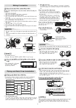
INSTALLATION DIAGRAM OF INDOOR AND OUTDOOR UNITS

INSTALLATION DIAGRAM OF INDOOR AND OUTDOOR UNITS

Part

code

Parts name

Q’ty

A

Refrigerant piping
Liquid side  :  Ø6.35 mm
  

Ø9.52 

mm


  (RAS-077, 107, 137SKV-E7)

Gas side 

:  Ø12.70 mm


(RAS-167SKV-E7)

One

each

B

Pipe insulating material
(polyethylene foam, 6 mm thick)

1

C

Putty, PVC tapes

One

each

Optional Installation Parts

•  Secure the outdoor unit with 

fi

 xing bolts and nuts if the unit is likely to be 

exposed to a strong wind.

•  Use Ø8 mm or Ø10 mm anchor bolts and nuts.
•  If it is necessary to drain the defrost water, attach drain nipple 

7

 and cap 

water proof 

8

 to the bottom plate of the outdoor unit before installing it.

Fixing bolt arrangement of outdoor unit


Insulate the refrigerant pipes separately 
with insulation, not together.

2

3

6

4

Insert the cushion between the indoor 
unit and wall, and tilt the indoor unit for 
better operation.

For the rear left and left piping

Wall

Make sure to run the drain hose sloped 
downward.

Do not allow the drain hose to get slack.

Cut the piping 
hole sloped 
slightly.

The auxiliary piping can be connected to 
the left, rear left, rear right, right, bottom 
right or bottom left.

Right

Rear 
right

Bottom
right

Rear
left

Bottom left

Left

6 mm thick heat resisting
polyethylene foam

1

Batteries

Flat head
wood screw

Remote control holder

Vinyl tape
Apply after carrying
out a drainage test.

Wireless remote control

Saddle

Extension drain hose
(Not available, provided 
by installer)

Shield pipe

(Attach to the front panel.)

Air 

fi

 lter

Hook

Installation
plate

Hook

65 mm or more

170 mm or more

170 mm or more

C mm or more

F mm or more

E mm or more

D mm or more

C mm or more

Remark :

•  Detail of accessory and installation parts can see in the 

accessory sheet.

•  Some pictures might be different from the actual parts.

Drain outlet

Air inlet

Air outlet

108 mm

28 mm

600 mm

320 mm

125 mm

86 mm

102 mm

90 mm

Ø25 mm

Drain outlet

Air inlet

Air outlet

280 mm

500 mm

53 mm

97 mm

Ø25 mm

RAS-077, 107, 137SAV-E6 RAS-167SAV-E5

C

600

600

D

400

600

E

45

100

F

100

100

RAS-077, 107, 137SAV-E6

RAS-167SAV-E5

Summary of Contents for RAS-077SAV-E6

Page 1: ...AIR CONDITIONER SPLIT TYPE INSTALLATION MANUAL ENGLISH Indoor unit RAS 077 107 137 167SKV E7 Outdoor unit RAS 077 107 137SAV E6 RAS 167SAV E5 1115551127 ...

Page 2: ...ectrical Work 3 Wiring Connection 4 Piping and Drain Hose Installation 4 Indoor Unit Fixing 5 Drainage 5 OUTDOOR UNIT 5 Installation Place 5 Precautions about Installation in Regions with Snowfall and Cold Temperatures 5 Refrigerant Piping Connection 6 Evacuating 6 Wiring Connection 7 OTHERS 7 Gas Leak Test 7 Remote Control A B Selection 7 Test Operation 7 Auto Restart Setting 7 CONTENTS EN ...

Page 3: ...HAT IT IS NOT BROKEN OR DISCONNECTED BEFORE INSTALLATION DO NOT INSTALL NEAR CONCENTRATIONS OF COMBUSTIBLE GAS OR GAS VAPORS FAILURE TO FOLLOW THIS INSTRUCTION CAN RESULT IN FIRE OR EXPLOSION TO PREVENT OVERHEATING THE INDOOR UNIT AND CAUSING A FIRE HAZARD PLACE THE UNIT WELL AWAY MORE THAN 2 M FROM HEAT SOURCES SUCH AS RADIATORS HEATERS FURNACE STOVES ETC WHEN MOVING THE AIR CONDITIONER FOR INSTA...

Page 4: ...re to run the drain hose sloped downward Do not allow the drain hose to get slack Cut the piping hole sloped slightly The auxiliary piping can be connected to the left rear left rear right right bottom right or bottom left Right Rear right Bottom right Rear left Bottom left Left 6 mm thick heat resisting polyethylene foam 1 Batteries Flat head wood screw Remote control holder Vinyl tape Apply afte...

Page 5: ...agram A place where there are no obstacles near the air inlet and outlet A place which allows easy installation of the piping to the outdoor unit A place which allows the front panel to be opened The indoor unit shall be installed as top of the indoor unit comes to at least 2 m height Also it must be avoided to put anything on the top of the indoor unit CAUTION 5 4 45 5 7 Side view Top view Indoor...

Page 6: ...the removed operation is performed Wiring Connection Wiring of the connecting cable can be carried out without removing the front panel 1 Remove the air inlet grille Open the air inlet grille upward and pull it toward you 2 Remove the terminal cover and cord clamp 3 Insert the connecting cable according to the local cords into the pipe hole on the wall 4 Take out the connecting cable through the c...

Page 7: ...t block a passage When the outdoor unit is to be installed in an elevated position be sure to secure its feet The allowable pipe length is up to 20 m If the length is over 15 m add 20 g of refrigerant for every additional meter of the pipe length The allowable height of outdoor unit installation site is up to 10 m A place where the drain water does not raise any problems CAUTION 1 Install the outd...

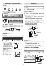
Page 8: ... a vacuum pump with counter flow prevention function so that inside oil of the pump does not flow backward into pipes of the air conditioner when the pump stops If oil inside of the vacuum pump enters the air conditioner which use R410A refrigeration cycle trouble may result 1 Connect the charge hose from the manifold valve to the service port of the packed valve at gas side 2 Connect the charge h...

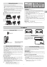
Page 9: ...usive use with the air conditioner This product can be connected to the mains Connection to fixed wiring A switch which disconnects all poles and has a contact separation of at least 3 mm must be incorporated in the fixed wiring CAUTION Check places for the indoor unit Check places for the outdoor unit Information To switch the TEST RUN COOL mode press RESET button for 10 seconds The beeper will m...

Page 10: ...1115551127 ...

Reviews: