– 11 –
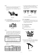
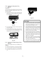
•
Fine flaring work shows even brightness on the
flared surface and uniform thickness of pipe.
•
Unsuccessful flaring work causes gas leaks,
therefore rework it.
Fig. 3-17
•
The above faulty flaring will cause gas leaks.
3-2-4. Finishing Work
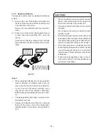
(1) Fix the pipe firmly on the flare die. Match the cen-
ters of both the flare die and the flaring punch,
and tighten flaring punch fully.
3-3. Pipe Process Points
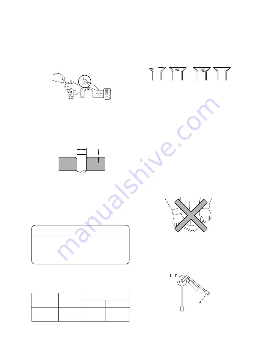
3-3-1. Pipe Bending
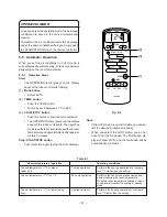
(1) Carefully bend by hand.
Note:
•
Collapsed pipe cause cooling failure.
Fig. 3-18
(2) Bend with pipe bender. (Since the insulation is
wound on, use the bender by sliding the insula-
tion to one side, or cutting it halfway.)
Fig. 3-19
Note:
•
Be sure to remove burrs to avoid unevenness on
the flare face which will cause gas leaks.
•
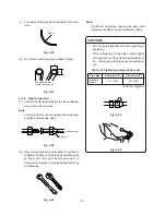
Cover the pipe end with a polyethylene bag and
on sheet.
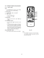
Fig. 3-15
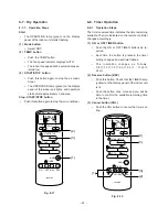
3-2-3. Point of Flaring
(1) The exact length of pipe protruding from the face
of the flare die is determined by the flaring, too.
Fig. 3-16
Note:
•
Too long a protrusion of pipe from the flaring tool
will result in too long a flare; If this happens, the
flare nut will not tighten and the joint will not seat.
•
Too small a protrusion will cause gas leaks.
CAUTION:
•
Too large protrusion of pipe results in impos-
sible tightening of the flare nut.
•
Too small a protrusion of pipe will cause gas
leaks due to insufficient flare surface.
•
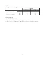
Table 3-1 shows the use of an imperial die and a
rigid die.
Table 3-1
Imperial
1.3
1.6
Rigid
0.7
1.0
A (mm)
D (mm)
6.35
9.52
Type of pipe
1/4”
3/8”
A
D
Slant
Scratch
Crack
Uneven
thickness

