– 37 –
9-3. Troubleshooting Flowcharts
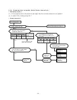
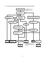
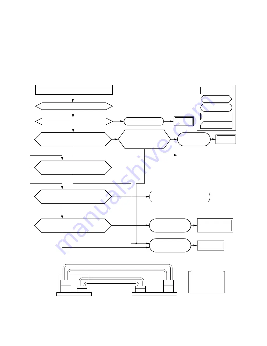
9-3-1. Power cannot be Turned on (No Operation at All)
<Preliminary checks>
(1) Is the supply voltage normal?
(2) Is the connection to the AC output O.K.?
(3) Are the connection of the primary side and the secondary side of the power transformer inserted into the PC
board?
Fig. 9-2 Power transformer connection diagram
Turn the power off for about 5 seconds
and then turn it on again.
Does the OPERATION lamp flash?
Does operation start when you press
the START/STOP button of the remote
control ?
Is the voltage display on the rear
panel of the PC board normal?
(12V DC or 5V DC)
Is 50Hz 220/230/240V AC supplied to the
primary side of the power source transformer?
Does the transmission
indicator of the remote
control blink normally,
and is the transmission
really performed?
Is 12V AC supplied to the secondary
side of the power transformer?
Remote control
is defective.
Replace.
YES
NO
Power transformer
is defective.
YES
Microcomputer is
defective.
Refer to above "Preliminary checks".
Or there is a defect before the power
transformer.
Replace power
transformer or the
PC board.
Replace the
PC board.
YES
YES
Refer to the figure below.
Refer to the below.
NO
NO
(Normal)
NO
NO
NO
YES
Probable main
causes
Check items
Remedies
Operations
Item by
symptoms
YES
Is the termal fuse set on?
Thermal fuse is defective.
Replace.
NO
CN32
Primary side
CN33
CN06
CN05
Secondary side
Transformer PC board (MCC-629)
Main PC board (MCC-639)
Color identification
WHI : WHITE
RED : RED
YEL : YELLOW
BLU : BLUE

