–
3
4
–
9-2. Primary Judgement of Trouble Sources
9-2-1. Role of Indoor Unit Controller
The indoor unit controller receives the operation commands from the remote control and assumes the following
functions.
•
Measurement of the draft air temperature of the indoor heat exchanger by using the thermo sensor (TA).
•
Louver motor control
•
Control of the indoor fan motor operation
•
Control of the LED display
•
Control of the outdoor unit compressor and the outdoor fan motor.
9-2-2. Display of Abnormalities and Judgement of the Abnormal Spots
The indoor unit of this machine observes the operation condition of the air conditioner and displays the contents
of the self-diagnosis as block displays on the display panel of the indoor unit.
Table 9-2-1
Block display
Description
A
OPERATION display blinking (1 Hz)
Power failure (when power is ON)
B
OPERATION display blinking (5 Hz)
Thermo. sensor (TA) short/break
C
OPERATION display blinking (5 Hz)
Heat exchanger sensor (TC) short/break
D
OPERATION display blinking (5 Hz)
Indoor fan lock, abnormality of indoor fan
E
OPERATION display blinking (5 Hz)
Indoor P.C. board failure
F
OPERATION, TIMER and FAN-ONLY display blinking (5 Hz)
•
Gas shortage, other refrigerant cycle trouble
•
Heat exchanger sensor open/break/short
•
Overload relay trouble
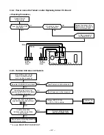
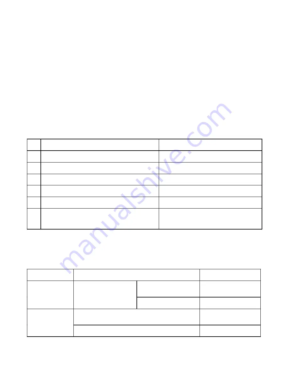
Symptom
Check
Primary judgement
Remote control is not possible.
The indoor part (including the
remote control) is defective.
No reaction on remote
control operation
Turn off the power once, turn it
on again and try to operate the
remote control again.
Remote control is possible.
OK.
The compressor operates.
The outdoor part is defective.
(outdoor fan motor)
The outdoor fan does
not rotate
The compressor does not operate.
The inside part is defective.
(1) Judgement from defective operation or abnormal operation
Table 9-2-2


