10
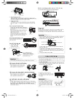
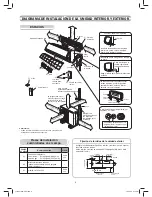
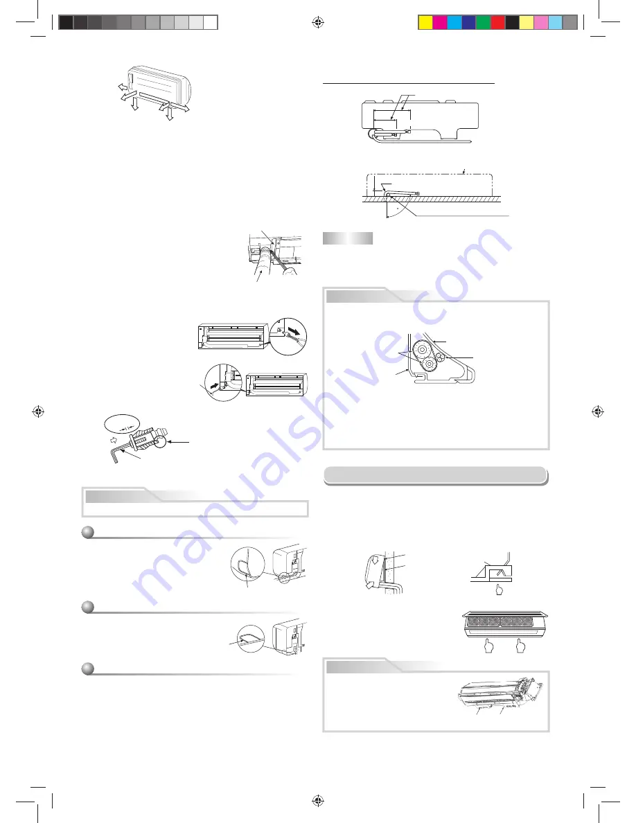
Bend the connecting pipe within a radius of 1-3/16 in. (30 mm).
To connect the pipe after the unit has been installed (
fi
gure)
NOTE
If the pipe is bent incorrectly, the indoor unit may be unstable on the wall.
After passing the connecting pipe through the pipe hole, connect the
connecting pipes to the refrigerant line and wrap facing tape around them.
CAUTION
• Bind the refrigerant lines (two) and connecting cable with facing tape
tightly. In case of leftward piping and rear-leftward piping, bind the
refrigerant lines (two) only with facing tape.
Indoor unit
Connecting cable
Refrigerant lines
Installation plate
• Carefully arrange pipes such that none of them stick out of the rear
plate of the indoor unit.
• Carefully connect the refrigerant lines and connecting pipes to one
another and cut off the insulating tape wound on the connecting pipe
to avoid double-taping at the joint; moreover, seal the joint with vinyl
tape, etc.
• Check for gas leaks before insulating.
80
Liquid side
Gas side
(Forefront of
fl
are)
Outward form of indoor unit
R 1-3/16 in. (R 30 mm) (Use polisin
(polyethylene) core or the like for bending
pipe.)
Use the handle of a screwdriver, etc.
16-9/16 in.
(420 mm)
1-5/8 in. (43 mm)
20-1/2 in.
(520 mm)
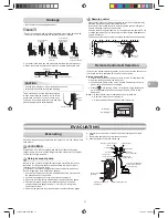
Indoor Unit Fixing
• To detach the indoor unit from the
mounting plate, pull the indoor unit toward
you while pushing its bottom up as shown
in the
fi
gure.
1
2
1
1. Pass the pipe through the hole in the wall and hook the indoor unit on the
upper hook of the installation plate.
2. Swing the indoor unit to the right and left to con
fi
rm that it is
fi
rmly hooked
up to the mounting plate.
3. While pressing the indoor unit onto the wall, hook it to the lower section
of the mounting plate. Pull the indoor unit toward you to con
fi
rm that it is
fi
rmly hooked up to the mounting plate.
Hook here.
Installation plate
Hook
Press
(unhook)
Push
Push
Information
%
Screw
%
Screw
Due to piping installation, in some cases
the lower section of the indoor unit may
not completely attach to the mounting
plate. In such a case, use the provided
screws
%
to
fi
x the unit to the mounting
plate.
Firmly insert the drain hose and drain cap; otherwise, water may leak.
In case of right or left piping
• After making slits of the front panel with a
knife or a making-off pin, cut them with a
pair of nippers or an equivalent tool.
In case of bottom right or bottom left piping
• After making slits of the front panel with a
knife or a making-off pin, cut them with a
pair of nippers or an equivalent tool.
Left-hand connection with piping
• Bend the connecting pipe so that it is laid within 1-5/8 in. (43 mm) above
the wall surface. If the connecting pipe is laid exceeding 1-5/8 in. (43 mm)
above the wall surface, the indoor unit may be unstable on the wall.
When bending the connecting pipe, make sure to use a spring bender to
avoid crushing the pipe.
CAUTION
Slit
Slit
How to remove the drain cap
Clip the drain cap with needle-nose
pliers and pull out.
How to
fi
x the drain cap
1) Insert a hexagon wrench
3/16 in. (4 mm) in the
center head of the cap.
2) Firmly insert the drain cap.
3/16 in.
(4 mm)
No gap
Do not apply lubricating oil
(refrigerant machine oil) when
inserting the drain cap. Application
causes deterioration and drain
leakage from the plug.
Insert a hexagon
wrench 3/16 in.
(4 mm).
How to remove the drain hose
• The drain hose can be removed by removing the
screw securing the drain hose and then pulling out
the drain hose.
• When removing the drain hose, be careful of any
sharp edges the steel plate may have. Sharp
edges can cause injuries.
• To install the drain hose, insert the drain hose
fi
rmly until the connection part contacts the heat
insulator, and then secure it with the original
screws.
Heat insulator
Drain hose
1. Die-cutting front panel slit
With a pair of nippers, cut out the slit on the leftward or right side of the
front panel for left or right connection, and the slit on the bottom left or right
side of the front panel for bottom left or right connection.
2. Changing drain hose
For leftward connection, bottom-leftward connection and rearleftward
connection’s piping, it is necessary to change the drain hose and drain
cap.
Right
Rear right
Bottom
right
Rear
left
Bottom left
Left
1110651824-2 EN.indd 10
1110651824-2 EN.indd 10
12/13/13 4:58 PM
12/13/13 4:58 PM
Summary of Contents for RAS-09 12EA Series
Page 39: ...1110251291 2 FR indd 13 1110251291 2 FR indd 13 12 17 13 5 03 PM 12 17 13 5 03 PM ...
Page 40: ...1110251291 2 FR indd 14 1110251291 2 FR indd 14 12 17 13 5 03 PM 12 17 13 5 03 PM ...
Page 79: ...1110651824 2 FR indd 13 1110651824 2 FR indd 13 12 17 13 2 15 PM 12 17 13 2 15 PM ...
Page 80: ...1110651824 2 FR indd 14 1110651824 2 FR indd 14 12 17 13 2 15 PM 12 17 13 2 15 PM ...


