FILE NO. SVM-07008
– 86 –
No.
Part name
Procedures
Remarks
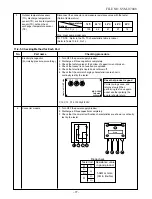
1) Perform work of item 1 of
1
and 1 of
2
.
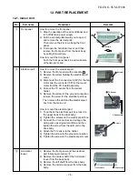
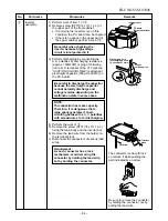
2) Remove the flange nut fixing the fan motor
and the propeller fan.
•
Flange nut is loosened by turning
clockwise.
(To tighten the flange nut, turn counter-
clockwise.)
3) Remove the propeller fan.
4) Disconnect the connector for the fan motor
from the inverter.
5) Remove the fixing screws (4 pcs.) holding
the fan motor by hand so that it does not
fall.
6) Cut the motor lead at the point which is
100 mm apart from the connector toward
the fan.
7) Use the connector used for the inverter,
and pinch the lead wires using the closed
end splice.
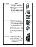
1) Perform work of item 1 of
1
, 1 of
2
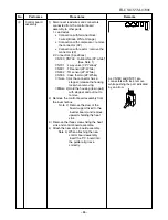
2) Extract refrigerant gas.
3) Remove the partition board.
(ST1T
∅
4 x 10
s
3 pcs.)
4) Remove the sound-insulation material.
5) Remove the terminal cover of the
compressor, and disconnect the lead wire
of the compressor thermo and the
compressor from the terminal.
6) Remove the pipe connected to the
compressor with a burner.
•
Make sure the flame does not touch the
4 way valve.
7) Remove the fixing screw of the base plate
and heat exchanger.
(ST1T
∅
4 x 10
s
2 pcs.)
8) Pull upward the refrigeration cycle.
9) Remove the nut fixing the compressor to
the base plate.
1) Perform work of item 1 of
1
, 1 of
2
,
and
3
.
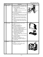
2) Remove the screw fixing the reactor.
(ST1T
∅
4 x 10 2 PCS.)
Fan motor
Compressor
ƒ
„
and
ƒ
…
Reactor
Compressor
Reactor
100
Fan motor
Propeller fan
Flange nut
Closed end
splice
s
.
Summary of Contents for RAS-10N3ACV Series
Page 16: ...FILE NO SVM 07008 15 4 2 Outdoor Unit C L C L ...
Page 17: ... 16 FILE NO SVM 07008 5 WIRING DIAGRAM 5 1 Indoor Unit ...
Page 18: ...FILE NO SVM 07008 17 5 2 Outdoor Unit ...
Page 83: ...FILE NO SVM 07008 82 P C board layout Solder side ...
Page 94: ...FILE NO SVM 03008 87 TOSHIBA CARRIER CORPORATION ...

