– 2 –
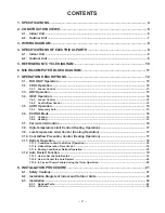
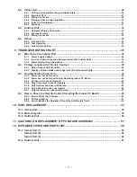
CONTENTS
1. SPECIFICATIONS ............................................................................................................ 4
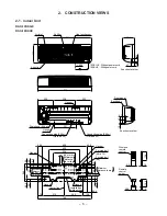
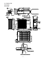
2. CONSTRUCTION VIEWS ................................................................................................ 6
2-1.
Indoor Unit .................................................................................................................................. 6
2-2.
Outdoor Unit ............................................................................................................................... 7
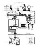
3. WIRING DIAGRAM .......................................................................................................... 8
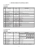
4. SPECIFICATIONS OF ELECTRICAL PARTS ................................................................. 9
4-1.
Indoor Unit .................................................................................................................................. 9
4-2.
Outdoor Unit ............................................................................................................................... 9
5. REFRIGERANT CYCLE DIAGRAM .............................................................................. 10
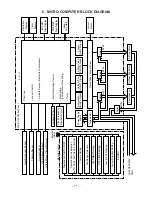
6. MICRO-COMPUTER BLOCK DIAGRAM ....................................................................... 11
7. OPERATION DESCRIPTIONS ....................................................................................... 12
7-1.
FAN ONLY Operation ............................................................................................................... 12
7-2.
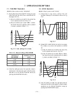
COOL Operation ....................................................................................................................... 12
7-2-1. Louver Control ...................................................................................................................................... 13
7-3.
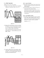
DRY Operation .......................................................................................................................... 13
7-4.
HEAT Operation ........................................................................................................................ 14
7-4-1. Louver Control ...................................................................................................................................... 14
7-4-2. Cool Airflow Control ............................................................................................................................. 14
7-5.
AUTO Operation ....................................................................................................................... 15
7-5-1. Temporary Auto ..................................................................................................................................... 15
7-6.
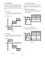
ECONO. Mode ........................................................................................................................... 16
7-6-1. Cooling ................................................................................................................................................... 16
7-6-2. Heating ................................................................................................................................................... 16
7-7.
Current Limit Control ............................................................................................................... 16
7-8.
High-Temperature Limit Control (Heating Operation) .......................................................... 17
7-9.
Low-Temperature Limit Control (Cooling Operation) .......................................................... 17
7-10. Cool Airflow Prevention Control (Heating Operation) ......................................................... 17
7-11. Defrost Operation ..................................................................................................................... 18
7-11-1. Condition to Start the Defrost Operation ............................................................................................ 18
7-11-2. Defrost Operation Time Control .......................................................................................................... 18
7-11-3. Ending Condition at Defrost Operation .............................................................................................. 18
7-12. Auto Restart Function ............................................................................................................. 19
7-12-1. How to Set the Auto Restart ................................................................................................................. 19
7-12-2. How to Cancel the Auto Restart .......................................................................................................... 20
7-12-3. In Case of Power Failure during the Timer Operation .......................................................................20
8. INSTALLATION PROCEDURE ...................................................................................... 21
8-1.
Safety Cautions ........................................................................................................................ 21
8-2.
Installation Diagram of Indoor and Outdoor Units ............................................................... 23
8-3.
Installation ................................................................................................................................ 24
8-3-1. Optional Parts ........................................................................................................................................24
8-3-2. Kit Parts ................................................................................................................................................. 25
Summary of Contents for RAS-10SAH-E
Page 51: ... 51 9 4 2 PC Board Layout Bottom View Top View ...
Page 62: ......

