– 43 –
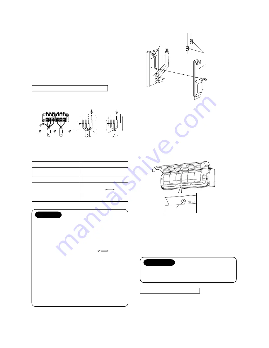
9-3-4. Wiring Connection
1. Remove the electric parts cover from the outdoor unit.
2. Connect the connecting cable to the terminal as
identified with their respective matched numbers on
the terminal block of indoor and outdoor unit.
3. When connecting the connecting cable to the
outdoor unit terminal, make a loop as shown
installation diagram of indoor and outdoor unit, to
prevent water coming in the outdoor unit.
4. Insulate the unused cords (conductors) with water
coming in the outdoor unit. Process them so that
they do not touch any electrical or metal parts.
Stripping length of connecting cable
Fig. 9-3-9
Model
Power source
Maximum running current
Installation fuse rating
Power cord
Terminal block
Connecting
cable
Connecting cable
Power
cord
Power
cord
Earth line
10
10
L N
30
10
30
40
10
40
1 2 3
RAS-13UKV-E
50/60 Hz
220 – 240 V Single phase
11A
25A
(D type
)
H07RN-F or 245IEC66
(1.5mm² or more)
CAUTION
• Wrong wiring connection may cause some
electrical parts burn out.
• Be sure to comply with local codes on running
the wire from outdoor unit to indoor unit.
(Size of wire and wiring method etc.)
• Every wire must be connected firmly.
• This installation fuse (25A D type
) must
be used for the power supply line of this air
conditioner.
• If incorrect or incomplate wiring is carried out, it
will cause an ignition or smoke.
• Prepare the power supply for exclusive use with
the air conditioner.
• This product can be connected to the mains.
Connection to fixed wiring : A switch which
disconnects all poles and has contact separa-
tion of at least 3mm must be incorporated in the
fixed wiring.
NOTE : Connecting cable
• Wire type : More than H07RN-F or 245IEC66
(1.0mm² or more)
9-3-5. Gas Leak Test
Fig. 9-3-10
• Check the flare nut connections for the gas leak with
a gas leak detector or soap water.
9-3-6. Test Operation
To switch the TEST RUN (COOL) mode, push TEMPO-
RARY button for 10 sec.
(The beeper will make a short beep.)
Fig. 9-3-11
9-3-7. Auto Restart Setting
This product is designed so that, after a power failure,
it can restart automatically in the same operating
mode as before the power failure.
Information
The product was shipped with Auto Restart
function in the off position.
Turn it on as required.
How to Set the Auto Restart
• Press and hold down the TEMPORARY button for
about 3 seconds. After 3 seconds, the electronic
beeper makes three short beeps to tell you the Auto
Restart has been selected.
• To cancel the Auto Restart, follow the steps de-
scribed in the section Auto Restart Function of the
Owner’s Manual.
Check places for
flare nut connections
(Indoor unit)
Check places
for outdoor unit
Electric parts
Valve cover
TEMPORARY button
Summary of Contents for RAS-13UAV-E
Page 1: ... ILE NO A02 001 SPLIT TYPE RAS 13UKV E RAS 13UAV E PRINTED IN JAPAN Mar 2002 ToMo ...
Page 73: ... 73 MCC 813 ...
Page 78: ......


